Note: Descriptions are shown in the official language in which they were submitted.
CA 02592280 2007-06-27
WO 2006/070239 PCT/IB2005/003768
TITLE OF THE INVENTION
Methods and Apparatus for Electro-Optical Hybrid Telemetry
FIELD OF THE INVENTION
The present invention relates generally to methods and apparatus for
gatliering data
from sub-surface formations. More particularly, the present inventior, relates
to methods and
apparatus for communicating between various downhole tools traversing a sub-
surface
formation and a surface data acquisition unit.
BACKGROUND OF THE INVENTION
Logging boreholes has been done for many years to enhance recovery of oil and
gas
deposits. In the logging of boreholes, one metliod of making measurements
underground
includes attaching one or more tools to a wireline connected to a surface
system. The tools are
then lowered into a borehole by the wireline and drawn back to the surface
("logged") through
the borehole while taking measurements. The wireline is usually an electrical
conducting
cable with limited data transmission capability.
Demands for higher data transmission rates for wireline logging tools is
growing
rapidly because of the higher resolution, faster logging speed, and additional
tools available for
a single wireline string. Although current electronic telemetry systems have
evolved,
increasing the data transmission rates from about 500 kbps (kilobit per
second) to 2Mbps
(Mega bits per second) over the last decade, data transmission rates for
electronic telemetry
systems are lagging behind the capabilities of the liigher resolution logging
tools. In fact, for
some combinations of acoustic/imagining tools used with traditional logging
tools, the desired
data transmission rate is more than 4 Mbps.
In addition, while higher data transmission rates are desirable, many tools in
current
use would have to completely reworked or replaced to incorporate new data
transmission
technologies. It would be desirable to facilitate faster data transmission
rates with minimal
changes to existing tools and equipment.
Furthermore, oilfield application of fiber optics sensors has been progressing
in recent
years for permanent monitoring of certain parameters. However, many downhole
applications
require high temperature operations, and optical devices such as laser diodes
and light emitting
diodes (LEDs) degrade rapidly or do not operate properly at high temperatures.
Therefore, use
1
CA 02592280 2007-06-27
WO 2006/070239 PCT/IB2005/003768
of fiber optics for two-way communication between surface systems and downhole
tools has
been limited.
SUlVIMARY OF THE INVENTION
The present invention addresses the above-described deficiencies and others.
Specifically, the present invention provides hybrid electro-optical telemetry
methods and
systems that may be particularly useful for subterranean investigation tools.
According to one
embodiment of the invention, there is a downhole telemetry system comprising a
surface data
acquisition unit having a surface optical telemetry unit, a downhole optical
telemetry cartridge
comprising a downhole electro-optic unit, and a fiber optic interface between
the surface data
acquisition unit and the downhole optical telemetry cartridge. The system also
includes a
downhole tool and a downhole electrical tool bus operatively connected between
the downhole
electro-optic unit and the downllole tool. There may be a plurality of
downhole tools
operatively connected to the downhole electrical tool bus. According to some
aspects of the
invention, inter-tool and intra-tool communication among the plurality of
downhole tools is
accomplished exclusively via electrical signals. Therefore, the plurality of
downhole tools
may communicate with one another exclusively via the downhole electrical tool
bus.
According to some aspects, the plurality of downhole tools communicate with
the
surface acquisition data unit exclusively via the fiber optic interface.
Moreover, the fiber optic
interface may comprise a single fiber, bi-directional system. The surface
optical telemetry unit
may include an optical source and the downhole optical telemetry cartridge
comprises a
litliium niobate modulator. The optical source may be located exclusively at
the surface.
According to some embodiments, the lithium niobate modulator comprises a
lithium niobate
substrate, a waveguide, and an optical circulator. The optical circulator
facilitates a single-
fiber input/output. The lithium niobate modulator may also comprises a lithium
niobate
substrate, a waveguide, and a reflector to facilitate single-fiber input and
output. The lithium
niobate modulator may fiu-ther comprise a polarization maintaining fiber
rotated an odd
multiple of approximately 45 degrees from a waveguide axis. The downhole
optical telemetry
cartridge may comprise a downhole optical source.
The downhole electro-optical unit may also comprise a photo detector for
demodulating optical signals into electrical signals, and the downhole optical
telemetry
cartridge may transmit demodulated electrical signals downhole to the downhole
tool via the
downhole electrical tool bus. The system may comprise a plurality of downhole
tools
2
CA 02592280 2007-06-27
WO 2006/070239 PCT/IB2005/003768
operatively connected to the downhole electrical tool bus, with each of the
plurality of
downhole tools having an uplink and downlink electrical data transceiver.
Another aspect of the invention provides a downliole optical telemetry system
comprising: a surface optical telemetry unit comprising an optical source and
a photodetector,
a downhole optical telemetry unit comprising an optical source, a
photodetector, an external
modulator, an optical interface extending between the surface and downhole
optical telemetry
uiiits, a 2x2 optical coupler disposed along the optical interface, wherein
the surface and
downhole optical telemetry units are selectable between a first mode of data
transmission
wherein the downhole optical source directly modulates data, and a second mode
of data
transmission wherein the surface optical source is modulated downhole by the
external
modulator. The surface optical source may be a CW (continuous wave) light
source, and the
surface optical telemetry unit may have an optical active scrambler. The
surface optical
telemetry unit may further include a directly modulated 1310 nm laser diode.
The downhole
optical telemetry unit optical source may include a high temperature, directly
modulated 1550
nm laser diode. The system may therefore have at least one 1310/1550 wave-
division
multiplexer disposed along the optical interface. The surface optical source
may be an
amplified spontaneous emission (ASE) light source capable of producing zero
degree of
polarization (DOP) broadband light. The ASE light source may also be created
by powering
an erbium-doped fiber amplifier with an input port terminated by an optical
terminator. The
uphole photodetector may comprise a photo diode operatively connected to an
uphole 1x2
optical switch for shifting optical input between the first and second modes.
Anotlier aspect of the invention provides a method of subterranean tool
communication. The method comprises providing a downhole electrical tool bus,
communicating downhole between downhole tools via the electrical tool bus,
providing an
optical tool bus between the downhole tools and a surface location, and
communicating data
from the downhole tools to the surface location via the optical tool bus. An
optical source for
the optical tool bus may be located at the surface location and an optical
modulator is located
downhole.
Another aspect of the invention provides a downhole optical telemetry system
comprising: a downhole optical telemetry cartridge, the downhole optical
telemetry cartridge
comprising an electro-optic unit, the electro-optic unit including an uplink
electrical-to-optical
modulator and a first optical wavelength separator assigned to separate a
first wavelength, and
a downlink optical-to-electrical demodulator. The system also includes a first
downhole tool
3
CA 02592280 2007-06-27
WO 2006/070239 PCT/IB2005/003768
comprising an optical uplink electrical-to-optical modulator and a second
optical wavelength
separator assigned to separate a second wavelengtli. The system includes a
downhole optical
tool bus operatively connected to the first downhole tool and the downhole
optical telemetry
cartridge for uplink data, and a downhole electrical tool bus operatively
comiected to the first
downhole tool and the downhole optical telemetry cartridge for downlink data.
The optical
wavelength separators may comprise Bragg gratings or AOTFs (Acousto-optic
tunable filters).
The downhole optical telemetry cartridge may include a first optical
circulator and the first
downhole tool further comprises a second optical circulator. The system may
comprise a
plurality of downhole tools, each having an uplink optical wavelength
separator assigned to
separate unique wavelengths and operatively connected to the downhole optical
tool bus,
where the plurality of downhole tools is also operatively coimected to the
downhole electrical
tool bus.
Another system according to the present invention is a downhole optical
telemetry
system comprising: a downhole optical telemetry cartridge, the downhole
optical telemetry
cartridge comprising an electro-optic unit, the electro-optic unit including
an uplink electrical-
to-optical modulator and a first AOTF tuned to a first wavelength and a
downlink optical-to-
electrical demodulator. The system also includes a first downhole tool
comprising an optical
uplink electrical-to-optical modulator and a second AOTF tuned to a second
wavelengtli, a
downhole optical tool bus operatively comzected to the first downhole tool and
the downhole
optical telemetry cartridge for uplink data, and a downhole electrical tool
bus operatively
connected to the first downliole tool and the downhole optical telemetry
cartridge for
communicating downlink data to the first downhole tool. The system may
comprise a plurality
of downhole tools, each comprising an uplink AOTF tuned to a different
wavelength and
operatively connected to the downhole optical tool bus, where the plurality of
downhole tools
is also operatively connected to the downhole electrical tool bus.
Another aspect of the invention provides a downhole optical telemetry system
including a downhole optical telemetry cartridge, the downhole optical
telemetry cartridge
comprising an electro-optic unit, the electro-optic unit including an uplink
electrical-to-optical
modulator having a Bragg grating assigned to or adapted to pass a first light
wavelength, and a
downlink optical-to-electrical demodulator. The system also includes a first
downhole tool
comprising an uplink electrical-to-optical modulator with a Bragg grating
assigned to or
adapted to pass a second light wavelength, a downhole optical tool bus
operatively connected
to the downhole tool and the downhole optical telemetry cartridge for uplink
data, and a
4
CA 02592280 2007-06-27
WO 2006/070239 PCT/IB2005/003768
downhole electrical tool bus operatively coimected to the first downhole tool
and the downhole
optical telemetry cartridge for downlink data or inter-tool communication. The
system may
include a plurality of downhole tools, each comprising an uplink electrical-to-
optical
modulator with a Bragg grating assigned to or adapted to pass a different
light wavelength and
operatively connected to the downhole optical tool bus. The plurality of
downhole tools is also
operatively connected to the downhole electrical tool bus. The system may
further include a
surface electro-optical unit having an optical source, such that there is no
downhole optical
source.
Another aspect of the invention provides a downliole optical telemetry system
including a downhole tool, the downhole tool having an uplink electrical-to-
optical modulator
and an optical source assigned to a first wavelength, and a downlink optical-
to-electrical
demodulator. The system also includes a plurality of downhole tool sensors,
each of the
plurality of downhole tool sensors including an uplink electrical-to-optical
modulator and an
optical source assigned to a unique wavelength, a downhole optical tool bus
operatively
connected to the optical sources of the plurality of downhole tool sensors for
transmitting
sensor data, and a downhole electrical tool bus operatively connected to the
downhole tool for
transmission of downlink data.
Anotlier aspect of the invention provides a downhole optical telemetry system
including a surface data acquisition unit, a downhole tool comprising an
electro-optic unit
operating at a first frequency, the electro-optic unit including a lithium
niobate modulator; and
a downhole optical tool bus operatively connected to the downhole tool. The
lithium niobate
modulator is modified to reduce direct current (DC) drift by rotating a
polarization maintaining
fiber an odd inultiple of approximately 45 degrees from a waveguide axis. The
surface optical
telemetry unit may provide an optical source that is modulated by the downhole
tool electro-
optic unit such that there is no downhole optical source. Alternatively, the
downhole tool may
include an optical source. The system may also include a second downhole tool
having a
second electro-optic unit operating at a second frequency, the second electro-
optic unit
including a lithium niobate modulator operatively connected to the downhole
optical tool bus
Another aspect of the invention provides a downhole optical telemetry system
including a downhole optical telemetry cartridge, the downhole optical
telemetry cartridge
comprising an electro-optic unit, the electro-optic unit including a first
uplink electrical-to-
optical modulator assigned to a first wavelength, and a downlink optical-to-
electrical
demodulator. The system also includes a downhole tool comprising a second
uplinlc electrical-
5
CA 02592280 2007-06-27
WO 2006/070239 PCT/IB2005/003768
to-optical modulator assigned to a second wavelength, a plurality of downhole
optical fiber
sensors, an uplink optical tool bus operatively connected to the plurality of
optical sensors, the
optical telemetry cartridge, and the first and second uplink electrical-to-
optical modulators;
and a downhole electrical tool bus operatively connected to the downhole tool
and the
downhole electro-optic unit of the downhole optical telemetry cartridge for
transmission of
downlink data. The first and second uplink electrical-to-optical modulators
comprise lithium
niobate waveguide type intensity modulators.
Additional advantages and novel features of the invention will be set forth in
the
description which follows or may be learned by those skilled in the art
through reading these
materials or practicing the invention. The advantages of the invention may be
achieved
through the means recited in the attached claims.
BRIEF DESCRIPTION OF THE DRAWINGS
The accompanying drawings illustrate preferred embodiments of the present
invention
and are a part of the specification. Together with the following description,
the drawings
demonstrate and explain the principles of the present invention.
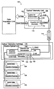
FIG. 1 is a schematic of downliole tools with an optical telemetry system
having an
inter-tool electrical tool bus and a single optical fiber according to one
embodiment of the
present invention.
FIG. 2a is a perspective view of an optical modulator arranged according to
one
embodiment of the present invention.
FIG. 2b is a schematic view of the angles related to the modulator of FIG. 2a.
FIG. 2c is a schematic a lithium niobate electrical-to-optical modulator
having an
optical circulator and a reflector to enable a single input/output fiber
according to one
embodiment of the present invention.
FIG. 2d is a schematic of a lithium niobate electrical-to-optical modulator
having an
optical circulator to enable a single input/output fiber according to another
embodiment of the
present invention..
FIG. 2e is a schematic of a lithium niobate electrical-to-optical modulator
having a
reflector to enable a single input/output fiber according to another
embodiment of the present
invention.
FIG. 3 is a schematic of a downhole tool with a fish-bone type optical
telemetry system
having an optical tool bus according to another embodiment of the present
invention.
6
CA 02592280 2007-06-27
WO 2006/070239 PCT/IB2005/003768
FIG. 4 is a schematic of a downhole tool with an in-line type optical
telemetry system
having an optical tool bus according to another embodiment of the present
invention.
FIG. 5 is a schematic of a downhole tool having a plurality of sensors, each
sensor
having an optical modulator and source according to one embodiment of the
present invention.
FIG. 6 is a schematic of a downhole tool having a plurality of optical sensors
and
coupled to an optical telemetry system according to one embodiment of the
present invention.
FIG. 7 is a schematic of a downhole tools with an optical telemetry system
having an
intertool electrical tool bus and multiple optical fibers according to one
embodiment of the
present invention.
FIG. 8 is schematic of an downhole redundant optical telemetry system
according to
one embodiment of the present invention.
FIG. 9 is schematic of an downhole redundant optical telemetry system
according to
another embodiment of the present invention.
FIG. 10 is a Ix2 optical switch for use with the redundant optical telemetry
systems of
FIGs. 8-9 according to one embodiment of the present invention.
FIG. 11 is a schematic of downhole tools with an in-line optical telemetry
system
having an electrical tool bus for downlink, an optical tool bus for uplink,
Bragg gratings for
wavelength separating, and optical circulators according to another embodiment
of the present
invention.
FIG. 12 is a schematic of downhole tools with an in-line optical telemetry
system
having an electrical tool bus for downlink, an optical tool bus for uplink,
and AOTFs (acousto-
optic tunable filters) for wavelength separating according to another
embodiment of the
present invention.
Throughout the drawings, identical reference numbers and descriptions indicate
similar, but not necessarily identical elements. While the invention is
susceptible to various
modifications and alternative forms, specific embodiments have been shown by
way of
example in the drawings and will be described in detail herein. However, it
should be
understood that the invention is not intended to be limited to the particular
forms disclosed.
Rather, the invention is to cover all modifications, equivalents and
alternatives falling within
the scope of the invention as defined by the appended claims.
7
CA 02592280 2007-06-27
WO 2006/070239 PCT/IB2005/003768
DETAILED DESCRIPTION OF THE PREFERRED EMBODIMENTS
Illustrative embodiments and aspects of the invention are described below. It
will of
course be appreciated that in the development of any such actual embodiment,
numerous
implementation-specific decisions must be made to achieve the developers'
specific goals,
such as compliance with system-related and business-related constraints, that
will vary from
one implementation to another. Moreover, it will be appreciated that such a
development
effort might be complex and time-consuming, but would nevertheless be a
routine undertaking
for those of ordinary skill in the art having the benefit of this disclosure.
The, present invention conteinplates methods and apparatus facilitating
optical
communications between downhole tools and sensors, and surface systems. The
use of fiber
optics between downhole tools and the surface provides higher -data
transmission rates than
previously available. The principles described herein facilitate active and
passive fiber optic
communications between downhole tools and sensors, and associated surface
systems, even in
high temperature environments. Some of the methods and apparatus described
below describe
a modified optical modulator that is particularly well suited to high
temperature applications,
but is not limited to high temperature environments.
As used throughout the specification and claims, the term "downhole" refers to
a
subterranean environment, particularly in a welibore. "Downhole tool" is used
broadly to
mean any tool used in a subterranean environment including, but not limited
to, a logging tool,
an imaging tool, an acoustic tool, and a combination tool. A "hybrid" system
refers to a
combination of optical and electrical telemetry, and does not refer to an
optical telemetry
system and an electrical sensor. A "bus" is a communications interface
electrically connecting
a plurality of separate sensor packages or major components. For example, as
contemplated
herein, a "bus" may electrically connect a plurality of geophones, but the
small connections
between multiple components or sensors in a single geophone or other single
package 'do not
constitute a "bus." The words "including" and "having" shall have the same
meaning as the
word "comprising."
Turning now to the figures, and in particular to FIG. 1, a schematic of a
downhole
optical telemetry system (100) according to principles of the present
invention is shown. The
optical telemetry system (100) includes a surface data acquisition unit (102)
in electrical
communication with or as a part of a surface optical telemetry unit (104). The
surface optical
telemetry unit (104) includes an uplink optical-to-electrical (OE) demodulator
(106) with an
optical source (108). The optical source (108) is preferably a laser, a light-
emitting diode
8
CA 02592280 2007-06-27
WO 2006/070239 PCT/IB2005/003768
(LED), white light source, or other optical source. The OE demodulator (106)
preferably
includes a photo detector or diode that receives optical uplink data sent at a
first light
wavelength (k up) and converts it to electrical signals that can be collected
by the data
acquisition unit (102)
The surface optical telemetry unit (104) also includes a downlink electrical-
to-optical
(EO) modulator (110). An optical source (112) is shown with the downlinlc EO
modulator
(110). Alternatively, the optical source may be placed downhole in the
borehole. The optical
source (112) may operate at a second light wavelength Q' down) that is
different from the first
light wavelength (a, up). The EO modulator (110) may include any available EO
modulator, or
it may include components described below with reference to a modified lithium
niobate
modulator.
The uplinlc OE demodulator (106) and the downlink EO modulator (110) are
operatively coimected to a single-fiber fiber optic interface (114). The fiber
optic interface
(114) provides a liigh transmission-rate optical communication link between
the surface
optical telemetry unit (104) and a downhole optical telemetry cartridge (116).
The downhole
optical telemetry cartridge (116) is part of the optical telemetry system
(100) and includes a
downhole electro-optic unit (118). The downhole electro-optic unit (118)
includes a downlink
OE demodulator (120) and an uplink EO modulator (122). The downhole optical
telemetry
cartridge (116) is shown without any optical sources. The downlink OE
demodulator (120)
and the uplink EO modulator (122) are of the type that passively respond to
optical sources.
Alternatively, one or both of the downlink OE demodulator (120) and the uplink
EO
modulator (122) may include an optical source. The downlink OE demodulator
(120) is
preferably a photo detector similar or identical to the uplink OE demodulator
(106).
The downhole electro-optic unit (118) is operatively connected to a downhole
electrical
tool bus (124). The downhole electrical tool bus (124) provides an electrical
communication
link between the downhole optical telemetry cartridge (116) and one or more
downhole tools,
for example the three downhole tools (126, 128, 130) shown. The downhole tools
(126, 128,
130) may each have one or more sensors (not shown) for measuring certain
parameters in a
wellbore, and a transceiver for sending and receiving data. Accordingly, the
downhole optical
telemetry system is a hybrid optical-electrical apparatus that may use
standard electrical
telemetry and sensor technology downhole with the advantage of the high
bandwidth fiber
optic interface (114) between the downhole components (optical telemetry
cartridge (116),
downhole tools (126, etc.)) and the data acquisition unit (102).
9
CA 02592280 2007-06-27
WO 2006/070239 PCT/IB2005/003768
Communications and data transfer between the data acquisition unit (102) and
one of
the downhole tools (126) is described below. An electronic Down Command from
the data
acquisition unit 102 is sent electrically to the surface optical telemetry
unit (104). The
downlink EO modulator (110) of the surface optical telemetry unit (104)
modulates the
electronic Down Command into an optical signal, which is transmitted via the
fiber optic
interface (114) to the downhole optical telemetry cartridge (116). Types of
fiber optic
interface (114) include wireline cables comprising a single optical fiber or
multiple optical
fibers. A single optical fiber may be facilitated by uniquely modified lithium
niobate
modulators discussed in more detail below with reference to FIGs. 2a-2e. The
downlink OE
demodulator (120) demodulates the optical signal back into an electronic
signal, and the
downhole optical telemetry cartridge (116) transmits the demodulated
electronic signal along
the downhole electrical tool bus (124) where it is received by the downhole
tool (126). The
demodulated electronic signal may be received by the other downhole tools
(128, 130) as well.
Similarly, Uplink Data from the downhole tools (126, etc.) is transmitted
uphole via
the downhole electrical tool bus (124) to the downhole optical telemetry
cartridge (116), where
it is modulated by the uplink EO modulator (122) into an optical signal and is
transmitted
uphole via the fiber optic interface (114) to the surface optical telemetry
unit (104). Sensors of
the downhole tools (126, etc.) may provide analog signals. Therefore according
to some
aspects of the invention, an analog-to-digital converter may be included with
each downhole
tool (126, etc.) or anywhere between the downhole tools (126, etc.) and the
uplink and
downlink modululators/demodulators (118, 122). Consequently, analog signals
from sensors
are converted into digital signals, and the digital signals are modulated by
the uplink EO
modulator (122) to the surface. According to some embodiments, the optical
source (108) is
input via the optical fiber (114), modulated by the EO modulator (122), and
output via the
same optical fiber (114) back to the surface optical telemetry unit (104). The
uplink OE
demodulator (106) demodulates the signal back into an electronic signal, which
is thereafter
communicated to the data acquisition unit (102). As mentioned above, the
downlink OE
demodulator (120) and the upliiik EO modulator (122) are passive and may only
modulate
optical sources from the surface, as the optical sources (108, 112) are
located at the surface
optical telemetry unit. Both uplink and downlink signals are preferably
transmitted full-duplex
using wavelength division multiplexing (WDM).
CA 02592280 2007-06-27
WO 2006/070239 PCT/IB2005/003768
The uplink EO modulator (122) of the downhole electro-optical unit (118)
preferably
comprises an external lithium niobate modulator (123) shown in more detail
witli reference to
various embodiments in FIGs. 2a-2e.
The lithium niobate modulator (123) may be an intensity modulator. Other
materials
that exhibit similar optical properties may also be used as an intensity EO
modulator. For
example, according to some aspects of the present invention, intensity
modulators may
comprise materials including, but not limited to: lithium tantalite, strontium
barium niobate,
gallium arsenide, and indium phosphate. Moreover, lithium niobate is not
limited to intensity
modulation. Lithium niobate may be used to make phase and polarization
modulators as well
according to some aspects of the invention.
However, lithium niobate intensity modulators have a polarization dependency,
and
therefore the polarization state of any input signal to lithium niobate
modulators is preferably
aligned. Therefore, according to the configuration of FIG. 1, the polarization
of input light is
randomized by a polarization scrambler (180) of the surface optical telemetry
unit (104), and a
polarizer (182) in front of the lithium niobate modulator (123) aligns the
polarization state.
Different wavelengths of uplink and downlink are selected, and the uplink and
downlink
signals are selected by the WDM technique. The polarizer (182) may comprise a
dielectric
thin film filter such as polacor, which is a near-infrared polarizing glass
material. The
polarizer (182) may be physically mounted between an output waveguide or
optical path and
the output fiber or interface (114), thus becoming integral with the waveguide
of the uplink EO
modulator (122).
The downlink EO modulator (110, FIG. 1) may be similar or identical to the
uplink EO
modulator (122), but this is not necessarily so. As shown in Fig. 2a, one
embodiment of the
lithium niobate modulator (123) is preferably a waveguide type phase modulator
and therefore
includes a lithium niobate substrate (132) with an optical path or waveguide
(134) disposed
therein. Operatively connected or coupled to the waveguide (134) is an optical
input, which
according to the embodiment of FIG. 2a, is the fiber optic interface (114).
The fiber optic
interface (114) carries a light beam that travels along the waveguide (134).
About the
waveguide (134) are first and second electrodes (136, 138). The first
electrode (136) is
grounded, and the second electrode (138) is driven by a voltage signal. As the
voltage across
the electrodes (136, 138) changes, a refractive index of the waveguide (134)
changes,
alternating the light beam passing through the waveguide (134) as the
refractive index rises
11
CA 02592280 2007-06-27
WO 2006/070239 PCT/IB2005/003768
and falls. The alternating of the refractive index modulates the phase of the
light, but the
output intensity remains essentially unchanged.
However, typical lithium niobate modulators are prone to DC bias drift,
especially
when there are fluctuations in temperature. In a feedback-bias-controlled
modulation
operation, a certain DC voltage is applied to the AC-driven electrode (138) as
a known initial
DC bias. This applied DC voltage is varied continuously to keep the state of
the optical output
modulation at the initial state. However, the initial DC bias depends on the
mechanical
fluctuations caused by changes in temperature, and can result in a change of
the optical
characteristics between two optical paths. Downhole wellbore environments are
well known
to have high temperatures and high temperature fluctuations, which influence
the refractive
index of the waveguide (134) and must be maintained within a controlled range
to allow
reliable EO modulation.
Therefore, according to the embodiment of FIG. 2b, the fiber optic interface
(114) is a
polarization maintaining fiber that is rotated an odd multiple of
approximately 45 degrees from
the waveguide (134, FIG. 2a). The waveguide (134, FIG. 2a) has an X-axis (140)
(ordinary
refractive index, no) and a Z-axis (142) (extraordinary refractive index ne).
Therefore,
according to one embodiment the fiber optic interface (114) is rotated an odd
multiple of
approximately 45 degrees with respect to the X and Z axes (140, 142) as shown.
By setting the
polarization maintaining fiber (the fiber optic interface (114)) at 45-degree
rotations (or an odd
multiple thereof), phase modulation can be converted to intensity modulation.
The downhole optical telemetry system (100) of FIG. 1 may operate with the
single
fiber optic interface (114) shown. However, in order to operate with a single
fiber, the lithium
niobate modulator (123) may be specially designed in one of a number of ways
to facilitate a
single input/output fiber (114). For example, FIGs. 2c-2e illustrate three
ways to create a
single input-output fiber. FIGs. 2c and 2d illustrate the single fiber lithium
niobate EO
modulator (123) with an optical circulator (175). FIG. 2c illustrates the
optical circulator (175)
downstream of the lithium niobate substrate (132), with an upstream optical
coupler (176).
The single-fiber lithium niobate EO modulator (123) of Fig. 2c also includes a
reflector (178).
Thus, an input light source may enter through the input/output fiber (114), be
modulated as it
passes through the waveguide (134), and pass a modulated output signal through
the optical
circulator (175). The output signal is then reflected by the reflector (178),
redirected through
the optical circulator (175) to a bypass fiber (179), reconnected to the
input/output fiber (114)
by the optical coupler (176), and returned uphole via the input/output fiber
(114).
12
CA 02592280 2007-06-27
WO 2006/070239 PCT/IB2005/003768
FIG. 2d illustrates the single fiber lithium niobate EO modulator (123)
without a
reflector. According to FIG. 2d, an input light source may enter through the
optical circulator
(175) via the input/output line (114) and be modulated. The output signal is
then redirected
via the bypass fiber (179) back to the optical circulator (175), and returned
uphole via the
single input/output fiber interface (114).
In some cases, for exainple if the modulation frequency is less than
approximately 100
Mbit/sec, the optical circulator (175) may be omitted as shown in Fig. 2e
because the
modulated light signal which is reflected by the reflector (178) can pass back
through the
lithium niobate substrate (132) without signal degradation.
The waveguide (134) may be created by molecular diffusion with a Ti or H
substrate in
the LiNbO3 substrate (132). If Ti is used, both no and ne are increased and
therefore,
polarization in both the X-axis (140, FIG. 2b) direction and Z-axis, (142,
FIG. 2b) direction
travel through the guide (134). A system of electrodes, rather than only the
first and second
electrodes (136, 138, FIG. 2a) may be deposited on the lithium niobate
substrate (132) to more
accurately generate an electrical field parallel to the Z-axis direction (142,
FIG. 2b). The
electric field parallel to the Z-axis (142, FIG. 2b) leads to a change of the
refractive index ne in
the Z-axis (142, FIG. 2b) direction while no is unchanged. Therefore, if light
arrives polarized
with two components, electrical field components EX and EZ, a phase shift is
generated between
EX and E. This phase shift is approximately proportional to the electrical
field generated by
the electrodes. The light travels along the waveguide (134), and, after
entering the modulator,
may be reflected back by the reflector and then travel back to through the
modulator as an
output. Due to their travel through the modulator, EX and EZ are phase shifted
by an angel cp. cp
depends on the length of the modulator and on the voltage applied on the
electrodes. EX and EZ
are then recombined in one single polarization by the polarizer (182, FIG. 1).
Therefore, the
light interferes with itself and the resulting intensity is given by:
I ~ 4 (1 + cos(rp))2
where I= initial intensity and assuming that Ex and EZ are substantially equal
Thus, an intensity modulation directly related to cp and therefore to the
voltage applied on the
electrodes is generated.
13
CA 02592280 2007-06-27
WO 2006/070239 PCT/IB2005/003768
The paragraphs above describing the lithium niobate modulator (123) exemplify
one of
the two principal branches of liglit intensity modulation. The lithium niobate
modulator (123)
is an example of light intensity modulation using the first branch: electro-
optic effect. The
other principal branch of intensity modulation is termed the electro-
absorption effect. The
electro-absorption effect is based on the Stark effect in quantum well
structure. Absorption
properties can be characterized by absorption as a function of wavelength. It
is well known
that by applying a voltage to a waveguide, it is possible to modify the energy
level and wave
function inside the quantum well, leading to a change in the light absorption
properties of the
quantum well. In particular, it is possible to create a so-called red-shift of
the quantum well
absorption that is directly related to the electrical field applied to it. The
red-shift leads to a
shift of the absorption curve of the device toward higher wavelengths. Using
this effect, a
light beam may be modulated. Both electro-optic modulators and electro-
absorption
modulators use an optical path or waveguide. According to principles of the
present invention,
electro-optic or electro-absorption modulators may be used and coupled only to
the single
input/output fiber (114). According to some embodiments, the substrate of the
electro-
absorption modi.ilators may comprise indium phosphide.
Although FIG. 1 illustrates a single optical fiber system, multiple fiber
systems are also
contemplated by the present invention. FIG. 7 shows the optical fiber system
(100) wherein
the uplink EO modulator (122) comprises the lithium niobate modulator (123),
and two fibers
(115a, 115b) comprise the fiber optic interface (114). One fiber (115a)
comprises an uplink
interface, and the other fiber (115b) comprises a downlink interface and may
also provide the
light source for the uplink EO modulator (122).
Referring next to FIG. 3, another embodiment of a downhole optical telemetry
system
is shown. The embodiment of FIG. 3 illustrates a downhole optical tool bus
(324) as opposed
to the downhole electrical tool bus (124) shown in FIG. 1. The downhole
optical tool bus
(324) comprises an extension of the fiber optic interface (114, FIG. 1) and is
therefore in
communication with the surface optical telemetry unit (104, FIG. 1). The
downhole optical
tool bus (324) is connected to one or more downhole tools, which according to
FIG. 3 include
a first optical tool bus tool (346) and a second optical tool bus tool (348).
The first and
second optical tool bus tools (346, 348) each include similar or identical
electro-optical units
(318). However, to distinguish between data from the first and second optical
tool bus tools
(346, 348), the electro-optical unit (318) of the first optical tool bus tool
(346) operates at a
first frequency (fl) and the electro-optical unit (318) of the second optical
tool bus tool (348)
14
CA 02592280 2007-06-27
WO 2006/070239 PCT/IB2005/003768
operates at a second frequency (fZ). Additional optical ultra bus tools may
also be in
communication with the downhole optical tool bus (324) and operate at other
different
frequencies.
The electro-optical units (318) are similar to the electro-optical unit (118,
FIG. 1)
described above, however, the electro-optical units (318) do not include
connections to an
electrical tool bus (124, FIG. 1). Accordingly, the electro-optical units
(318) include a
downlink OE demodulator (320) and an uplink EO modulator (322). As described
above, the
uplink EO modulator (322) of the downhole electro-optical unit (318) is
preferably a lithium
niobate modulator shown in more detail with reference to FIGs. 2a-2e above.
Similarly, the
downlink OE demodulator (320) is preferably a photo detector similar or
identical to the
uplink OE demodulator (106, FIG. 1).
Referring next to FIG. 4, another embodiment of a downhole optical telemetry
system
is shown. The embodiment of FIG. 4 also illustrates a downhole optical tool
bus (424) similar
to the optical tool bus (324) of FIG. 3. The downhole optical tool bus (424)
is in
communication with the surface optical telemetry unit (104) as sliown in FIG.
1. The
embodiment of FIG. 4 also includes a downhole optical telemetry cartridge
(416). The
downhole optical telemetry cartridge (416) comprises an electro-optic unit
(418). However,
unlike the electro-optic unit (318) of FIG. 3, the electro-optical unit (418)
of FIG, 4 includes an
uplink electrical-to-optical modulator (422) and may optionally have an in-
line reflective unit
or wavelength separator such as a Bragg grating assigned to or allowing
passage of a first
wavelength (M) of light. The electro-optical unit (418) also includes a
downlink optical-to-
electrical demodulator (420) similar or identical to the downlink OE
demodulator (120) of
FIG. 1.
Further, the embodiment of FIG. 4 includes a downliole electrical tool bus
(425). The
downhole electrical tool bus (425) transmits downlink commands and provides
inter-tool
and/or intra-tool communication in a manner similar to that described in FIG.
1. However,
unlike the embodiment of FIG. 1, uplink data is transmitted via the downhole
optical tool bus
(424) directly from the downhole tools (426, 428, 430) instead of first being
modulated by the
optical telemetry cartridge 416. Again, the downhole optical tool bus (424)
coinprises the
fiber optic interface (114, FIG. 1) in this instance. Accordingly, the
embodiment of FIG. 4
includes one or more downhole tools (426, 428, 430), each comprising an uplink
electrical-to-
optical modulator (422) and a mechanism such as a wavelength separator to
distinguish
between tool signals. The upliiik electrical-to-optical modulators (422) are
operatively
CA 02592280 2007-06-27
WO 2006/070239 PCT/IB2005/003768
connected to the optical tool bus (424), thus uplink data from sensors in the
downhole tools
(426, 428, 430) is modulated at each tool and transmitted directly to the
downhole optical tool
bus (424).
Referring next to FIG. 5, another embodiment of a downhole optical telemetry
system
according to the present invention is shown. The system of FIG. 5 includes a
downhole tool
(526) having an uplink EO modulator (522) with its own high temperature light
source (508)
assigned to a first wavelength (M) that may be directly modulated. The
downhole tool (526)
also includes a downlink OE demodulator (520) and a plurality of sensors (550,
552, 554).
The downlink OE demodulator (520) is preferably a photo detector. Each of the
plurality of
sensors (550, 552, 554) has an uplink EO modulator (522) with a light source
(512) assigned
to a unique wavelength (k2, ),3, kn, respectively). Therefore, the surface
optical telemetry unit
(104, FIG. 1) may or may not include a source. Each of the EO modulators (522)
may
comprise the structure of the modified lithiuin niobate modulator (123, FIGs.
2a-2e) described
above with reference to FIGs. 2a-2e. In the event that multiple lithium
niobate modulators are
provided, they are operated at the same wavelength.
The downhole optical telemetry system of FIG. 5 also includes a downhole
optical tool
bus (524) operatively connected to the downhole tool (526) and the electrical
sensors (550,
552, 554). Accordingly, the uplink EO modulators (522) modulate electrical
signals from the
sensors (550, 552, 554) and transmit them along the downhole optical tool bus
(524) and on to
the surface optical telemetry unit (104, FIG. 1).
Referring now to FIG. 6, another embodiment of a downhole optical telemetry
system
according to the present invention is shown. The system of FIG. 6 includes the
data
acquisition system (102) and surface optical telemetry unit (104) similar to
that shown in FIG.
1. The system may also include a surface optical sensor unit (660) with an
optical sensor
integration system (662). Downhole the system includes an optical telemetry
cartridge (616)
comprising an electro-optical unit (618). The electro-optical unit (618)
includes a first EO
modulator (622) without a source. The first EO modulator (622) is assigned to
a first light
wavelength (k1), possibly using a Bragg grating or other wavelength separator.
The electro-
optical unit (618) also includes a downlink OE demodulator (620), which is
preferably a photo
detector for demodulating downlink commands. The downlink OE demodulator (620)
demodulates optical signals into electrical signals and transmits them along a
downhole
electrical tool bus (625).
- 16
CA 02592280 2007-06-27
WO 2006/070239 PCT/IB2005/003768
The system of FIG. 6 also includes at least one downhole tool (626) including
a second
EO modulator (623) similar or identical to the first EO modulator (622) but
assigned to a
different wavelength (X2). The first and second EO modulators (622, 623) may
comprise the
structures shown and described with reference to FIGs. 2a-2e. The first and
second EO
modulators (622, 623) are operatively connected to a downhole optical tool bus
(624) which is
part of the fiber optic interface (114, FIG. 1). In addition, the downhole
optical tool bus (624)
is operatively connected to one or more optical fiber sensors, which according
to FIG. 6
include four optical fiber sensors (670, 672, 674, 676) The optical fiber
sensors (670, 672,
674, 676) may include permanent sensors in a wellbore or parts of the downhole
tool (626),
and may include, but are not limited to, temperature sensors, pressure
sensors, and optical fluid
analyzers. Signals from the optical fiber sensors (670, 672, 674, 676) are
modulated and
transmitted uphole via the optical tool bus (624). Use of the optical sensors
(670, 672, 674,
676) may necessitate the surface optical sensor unit (660), which includes an
interface (680)
with the data acquisition unit (104).
Operation of the embodiment of FIG. 6 is similar to the description
accompanying FIG.
1. Downlink data or commands are modulated, transmitted along the downhole
optical tool
bus (624), demodulated by the optical telemetry cartridge, and retransmitted
to the downhole
tool (626) via the electrical tool bus (625). Uplink data is modulated by one
of the uplink EO
modulators (622, 623) and transmitted uphole via the optical tool bus (624).
The surface
optical telemetry unit (104) then demodulates and retransmits the data to the
data acquisition
unit (102).
According to some aspects of the invention, an optical telemetry system may
include at
least two selectable modes of optical data transmission, advantageously
providing a redundant
optical path. For example, as shown in Fig. 8, an optical telemetry system
(800) includes a
surface optical telemetry unit (804) having a first optical source that may
comprise a 1550nm
continuous wave (CW) light source (808) and a photo detector such as a 1550nm
photo diode
(806). The surface optical telemetry unit (804) may also have a second
directly modulated
optical source such as a 1310nm laser diode (815) for downlink communication.
The optical
telemetry system (800) also has a downhole optical telemetry unit (816) that
includes an
optical source such as a 1550nm high temperature laser diode (809). The
downhole optical
telemetry unit (816) includes a photo detector such as a 1310nm photo diode
(820), and an
external modulator such as a lithium niobate modulator (822) that may comprise
the structure
discussed above. An optical interface such as a 121cm fiber (814) extends
between the surface
17
CA 02592280 2007-06-27
WO 2006/070239 PCT/IB2005/003768
optical telemetry unit (804) and the downhole optical telemetry unit (816).
Along the 12km
fiber (814) is a 2x2 optical coupler (811) , preferably located the downhole
optical telemetry
unit (816). The surface optical telemetry unit (804) and the downhole optical
telemetry unit
(816) are selectable between a first data transmission mode and at least a
second data
transmission mode. A first data transmission mode coinprises use of the 1550nm
laser diode
(809) to directly modulate data, which is sent uphole via the 12km optical
fiber (814) through
the 2x2 coupler (811), and ultimately to the 1550nm photo diode (806). A
second data
transmission mode comprises modulating light from the 1550 CW light source
(808) with the
lithium niobate modulator (822). The modulated light is sent uphole via the
12km optical fiber
(814) through the 2x2 coupler (811), and ultimately to the 1550nm photo diode
(806).
Accordingly, if one data transmission mode fails, for exainple, due to a
malfunction of the
1550nm laser diode (809), the other data transmission mode may still be used.
The optical
telemetiy system (800) may also include additional components, such as an
isolator (817),
inline PC (819), erbium-doped fiber amplifier (EDFA) (821), 1x2 coupler (835),
and wave-
division multiplexer (WDM) couplers (837) to facilitate the redundant,
selectable system.
The quality of the data transmitted via the lithium niobate modulator (822)
may depend
on the polarization state of the input CW light from the 1550mn CW light
source (808). For a
single mode fiber, the polarization state is changed rapidly by many external
factors which
may include fiber stress, twist, movement, bending, etc. In subterranean
applications, logging
cable (optical interface (814)) moves dynamically throughout the logging and
measurement
operation. Due to the dynamic movement of the optical logging cable, the
polarization state of
the light source rapidly changes and may induce substantial error to the
modulated signal. As
a result, the bit error rate of the transmitted signal might be poor. To
compensate for the
dependency on the light polarization state, an active scrambling method may be
introduced.
By definition, an optical active scrainbler converts any polarized input light
source to un-
polarized output light. With an active scrambler (813) coupled to the 1550 CW
light source
(808), less than 5% Degree of Polarization (DOP) output light can be achieved.
Accordingly,
more than 95% of the output light from the active scrambler (813) is un-
polarized. By sending
highly un-polarized light into the lithium niobate modulator (822), the
dependency of
polarization state effect can be minimized and the quality of the data
transmission is greatly
improved.
Alternatively, as illustrated in Fig. 9, optical modulator dependency on the
polarization
state may be reduced by using Amplified Spontaneous Emission (ASE) broadband
light.
18
CA 02592280 2007-06-27
WO 2006/070239 PCT/IB2005/003768
Theoretically, ASE light sources can produce zero DOP broadband light. There
are many
ways to obtain an ASE light source (941). For example, one way is to buy a
commercially
available high power ASE compact light source module. Another way to produce
ASE light is
to power an EDFA with an input port terminated by an optical terminator. Zero
DOP light
completely removes modulator dependency on the polarization light state. In
addition, using
an ASE light source may reduce the number of optical components located at the
surface,
simplify the design circuitry, and reduce space and cost.
In order to switch between two or more different data transmission modes, the
optical
telemetry system (800) may include an optical switch (1043) shown in Fig. 10.
The optical
switch (1043) enables sharing the same photodiodes (806, 820) for each mode.
The optical
switch (1043) is commercially available and shifts the optical input to a
desired output optical
path.
Referring next to FIG. 11, another embodiment of a downhole optical telemetry
system
is shown. The embodiment of FIG. 11 illustrates a downhole optical tool bus
(1124). The
downhole optical tool bus (1124) is shown in communication with the surface
optical
telemetry unit (104) in FIG. 1. The enibodiment of FIG. 11 includes a downhole
optical
telemetry cartridge (1116). The downhole optical telemetry cartridge (1116)
comprises an
electro-optic unit (1118). The electro-optical unit (1118) of FIG. 11 includes
an uplink
electrical-to-optical lithium niobate modulator (1122) and an optical
separator, for example a
Bragg grating, assigned to a first wavelength (k1). The electro-optical unit
(1118) also
includes a downlink optical-to-electrical demodulator (1120) similar or
identical to the
downlink OE demodulator (120) of FIG. 1.
Further, the embodiment of FIG. 11 includes a downhole electrical tool bus
(1125).
The downhole electrical tool bus (1125) transmits downlink commands and
provides inter-tool
and/or intra-tool communication in a manner similar to that described in FIG.
1. The
downhole optical tool bus (1124) comprises an extension of the fiber optic
interface (114, FIG.
1). The embodiment of FIG. 11 includes one or more downhole tools (1126, 1128,
each
comprising an uplinlc electrical-to-optical modulator (1122) and a separator
such as a Bragg
grating assigned to a different wavelength (k2,,%3). The uplink electrical-to-
optical modulators
(1122) are operatively connected to the optical tool bus (1124). Uplink data
from sensors in
the downhole tools (1126, 1128) may be modulated at each tool and transmitted
directly to the
downhole optical tool bus (1124).
19
CA 02592280 2007-06-27
WO 2006/070239 PCT/IB2005/003768
To facilitate downhole optical data modulation using a surface optical source,
the
electro-optical unit (1118) and the downhole tools (1126, 1128) each comprise
optical
circulators, which include three optical circulators (OC, OCla, OClb) for the
electro-optical
unit (1118), two optical circulators (OC2a, OC2b) for the first downhole tool
(1126), and two
optical circulators (OC3a, OC3b) for the second downhole tool (1128). A 3dB
coupler (1145)
may be located within the electro-optical unit (1118) upstream of and
connected to both the
downlink OE demodulator (1120) and the optical circulator (OC). Therefore,
light from the
surface may pass downhole through the optical circulators as indicated in FIG.
11 and be
directed to one or more of the uplink electrical-to-optical modulators (1122).
The light is
modulated by one or more of the uplink electrical-to-optical modulators (1122)
and returned
uphole througli the optical circulators to back to the fiber optic interface
(114).
Alternative to the use of Bragg gratings to separate light wavelengths and
optical
circulators to direct the light as shown in FIG. 11, some systems may use
AOTFs and
reflectors. Accordingly, FIG. 12 illustrates replacement of the Bragg gratings
with AOTFs and
the use of reflectors or mirrors (1278) to redirect light received from the
surface and modulated
by uplink EO modulators (1122). The electro-optical unit (1118) of the optical
telemetry
cartridge (1116) may thus include AOTF1, and the downhole tools (1126; 1128)
may include
AOTF2 and AOTF3, respectively. Each of the AOTFs is tuned to a different
wavelength,
enabling the surface optical telemetry unit to distinguish signals from
different tools.
The preceding description has been presented only to illustrate and describe
the
invention and some examples of its implementation. It is not intended to be
exhaustive or to
limit the invention to any precise form disclosed. Many modifications and
variations are
possible in light of the above teaching.
The preferred aspects were chosen and described in order to best explain the
principles
of the invention and its practical application. The preceding description is
intended to enable
others skilled in the art to best utilize the invention in various embodiments
and aspects and
with various modifications as are suited to the particular use contemplated.
It is intended that
the scope of the invention be defined by the following claims.