Language selection

Search

Patent 2592310 Summary

Third-party information liability

Some of the information on this Web page has been provided by external sources. The Government of Canada is not responsible for the accuracy, reliability or currency of the information supplied by external sources. Users wishing to rely upon this information should consult directly with the source of the information. Content provided by external sources is not subject to official languages, privacy and accessibility requirements.

Claims and Abstract availability

Any discrepancies in the text and image of the Claims and Abstract are due to differing posting times. Text of the Claims and Abstract are posted:

  • At the time the application is open to public inspection;
  • At the time of issue of the patent (grant).
(12) Patent: (11) CA 2592310
(54) English Title: METHOD FOR PRODUCING A PRICKING ELEMENT
(54) French Title: PROCEDE DE PRODUCTION D'UN ELEMENT DE PIQUAGE
Status: Deemed expired
Bibliographic Data
(51) International Patent Classification (IPC):
  • A61B 5/15 (2006.01)
(72) Inventors :
  • GRISS, PATRICK (Switzerland)
  • ZIPFEL, MARZELLINUS (Germany)
  • LOPEZ, ANGEL (Germany)
(73) Owners :
  • F. HOFFMANN-LA ROCHE AG (Switzerland)
(71) Applicants :
  • F. HOFFMANN-LA ROCHE AG (Switzerland)
(74) Agent: NORTON ROSE FULBRIGHT CANADA LLP/S.E.N.C.R.L., S.R.L.
(74) Associate agent:
(45) Issued: 2011-10-18
(86) PCT Filing Date: 2005-12-10
(87) Open to Public Inspection: 2006-06-29
Examination requested: 2007-09-24
Availability of licence: N/A
(25) Language of filing: English

Patent Cooperation Treaty (PCT): Yes
(86) PCT Filing Number: PCT/EP2005/013266
(87) International Publication Number: WO2006/066744
(85) National Entry: 2007-06-15

(30) Application Priority Data:
Application No. Country/Territory Date
04029926.5 European Patent Office (EPO) 2004-12-17

Abstracts

English Abstract


The invention concerns a process for producing a lancing element in which a
flat
shaped member (12) is formed from a flat material (22) by applying a mask (24)
and
allowing an etching agent to act upon it wherein at least a part of the flat
shaped
member (12) is shaped as a tip (16, 16'). According to the invention it is
proposed
that the mask (24) is provided with a shaping area (30) for the tip to be
formed (16,
16') and with a screening area (32) which extends distally beyond this shaping
area
to prevent the tip from being etched off at the front (16, 16') and that a
sharp tip (16,
16') is exposed by laterally undercutting the side flanks (34, 36) of the
shaping area
and screening area (32).


French Abstract

L'invention concerne un procédé de production d'un élément de piquage. On forme un élément plat (12) à partir d'un matériau plat (22) en appliquant un masque (24) et en utilisant un agent de gravure. Au moins une partie de l'élément plat (12) a la forme d'une pointe (16,16'). Selon l'invention, le masque (24) est pourvu d'une zone de façonnage (30) destiné à la pointe (16,16') à former, prolongée d'une zone écran (32) distale qui empêche le rongeage frontal de la pointe (16,16'). Le sous-rongeage latéral des flancs latéraux (34,36) de la zone de formage et d'écran (32), permet de libérer une pointe affilée (16,16').

Claims

Note: Claims are shown in the official language in which they were submitted.


-11-
Claims

1. Process for producing a lancing element in which a flat shaped member (12)
is
formed from a flat material (22) by applying a mask (24) and allowing an
etching agent to act upon it wherein at least a part of the flat shaped member

(12) is shaped as a tip (16, 16') for piercing into a body part of a test
subject,
wherein the mask (24) is provided with a shaping area (30) for the tip (16,
16')
to be shaped and with a screening area (32) which extends distally beyond this

shaping area to prevent the tip (16, 16') from being etched off at the front,
characterized in that at least one side flank (34) is bent or concavely curved

in the junction between the shaping area (30) and screening area (32) so that
the screening area (32) has a constant or increasing width over a given
screening length where it connects with the shaping area (30) and a sharp tip
(16, 16') is exposed only by laterally undercutting the side flanks (34, 36)
of
the shaping area and screening area (32).

2. Process according to claim 1, characterized in that the shaping area (30)
of
the etching mask narrows towards the screening area (32).

3. Process according to claim 1 or 2, characterized in that the shaping area
(30)
is linearly chamfered at least on one side.

4. Process according to claim 1, characterized in that the screening length is

larger than the proximal undercutting width due to the action of the etching
agent.

5. Process according to any one of claims 1 to 4, characterized in that the
tip
(16, 16') is shaped by a constriction (38) in the mask (24).


-12-
6. Process according to claim 5, characterized in that the width of the
constriction (38) should be less than twice the lateral undercutting width.

7. Process according to claim 5 or 6, characterized in that the screening area
(32) is widened again after the constriction (38).

8. Process according to any one of claims 1 to 7, characterized in that the
screening area (32) has a bridge section (40) that widens in the distal
direction
relative to the tip (16, 16') that is to be formed.

9. Process according to any one of claims 1 to 8, characterized in that the
undercutting etching width is larger or smaller than the etching depth.
10. Process according to any one of claims 1 to 9, characterized in that the

etching agent is applied in a dipping bath or by being sprayed onto the flat
material.

11. Process according to any one of claims 1 to 10, characterized in that the
etching agent is applied at an overpressure relative to the surroundings.

12. Process according to any one of claims 1 to 11, characterized in that the
flat
material (22) is processed from roll to roll by photochemical mask etching.
13. Process according to claim 12, characterized in that the flat material
(22) is

formed from stainless steel sheet metal.


- 13 -

14. Process according to any one of claims 1 to 13, characterized in that the
thickness of the flat material (22) is selected to be between 1 mm and
0.01 mm.

15. Process according to any one of claims 1 to 14, characterized in that the
lancing element is provided with a capillary channel (18) to transport the
body
fluid that is formed by a channel slot (42) in the mask (24), and that the
distal
ends of the channel walls (44) are shaped as a sharp tip (16').

16. Process according to claim 15, characterized in that the screening areas
(32)
for the tips (16') of the channel walls (44) are delimited on one side by the
channel slot (42).

17. Process according to any one of claims 1 to 14, characterized in that the
flat
material (22) is provided on both sides with the mask (24) wherein a pointed
lancing shaft (14) is etched free on one side and a capillary channel (18)
with
pointed channel walls (44) that extends towards the lancing shaft (14) is
etched
free on the other side.

18. Process according to any one of claims 1 to 17, characterized in that the
mask (24) is provided with a compensation opening (54) at a lateral distance
from an undercut edge section (56), and that an edge contour (48) of the flat
shaped member (12) is etched away from the edge through the compensation
opening (54) under the action of the etching agent.

19 Process according to any one of claims 1 to 17, characterized in that said
lancing element is for withdrawing a body fluid.


-14-
20. Process for producing a lancing element in which a flat shaped member (12)
is
formed from a flat material (22) by applying a mask (24) and allowing an
etching agent to act upon it wherein at least a part of the flat shaped member
(12) is shaped as a tip (16, 16') for piercing into a body part of a test
subject,
wherein the mask (24) is provided with a compensation opening (54) at a
lateral distance from an undercut edge section (56), and an edge contour (48)
of the flat shaped member (12) is etched away from the edge through the
compensation opening (54) under the action of the etching agent,
characterized in that the compensation opening (54) is positioned only at the
side of a central axis running towards the tip (16, 16') that is to be shaped
so
that a strip of the mask is retained in front of the tip (16, 16') along the
central
axis and the tip (16, 16') is screened from being etched off at the front.

21. Process according to claim 18 or 20, characterized in that the
compensation
opening (54) runs as a slot or chain of holes in the mask (24) along the edge
section (56).

22. Process according to any one of claims 18, 20 or 21, characterized in that
the
compensation opening (54) has a smaller inner width than a cut-away in the
mask (62) adjoining the edge section (56).

23. Process according to any one of claims 18 or 20 to 22, characterized in
that a
mask bridge (60) runs between the mask edge and the compensation opening
(54), and that the width of the mask bridge (60) is less than the undercutting
width of the etching agent measured form the edge of the mask.


-15-
24. Process according to any one of claims 18 or 20 to 23, characterized in
that

the compensation opening (54) is arranged in a shaping area (30) of the mask
(24) for the tip (16, 16) to be shaped.

25. Process according to claim 24, characterized in that the compensation
opening (54) is arranged in said shaping area (30) and in a screening area
(32)
of the mask (24) for the tip (16, 16) to be shaped.

26. Process according to any one of claims 18 or 20 to 25, characterized in
that
the compensation opening (54) is laterally spaced apart from a side flank (34)
of the mask (24) that is bent or concavely curved distally beyond the tip (16,
16') to be shaped.

27. Process according to any one of claims 18 or 20 to 26, characterized in
that
said lancing element is for withdrawing a body fluid.

Description

Note: Descriptions are shown in the official language in which they were submitted.


CA 02592310 2010-11-04

Method for Producing a Pricking Element

The invention concerns a process for producing a lancing element in particular
for
withdrawing a body fluid in which a flat shaped member is formed from a flat
material by applying a mask and allowing an etching agent to act upon it
wherein at

least a part of the flat shaped member is shaped as a tip for piercing into a
body part of
a test subject.

Lancing elements of this type allow the analysis of very small amounts of
fluid
especially in bioanalytics, such as for example those which are withdrawn in
situ as
capillary blood for blood glucose determinations. Such microfluidic systems,
in
addition to the microscopic volumes (microliters and less) are also
characterized by
structural elements of increasingly smaller dimensions which allow capillary
forces to
be utilized and can be implemented in so-called disposables in a suitable
manner for
mass production. Although manufacturing processes especially in the form of
mask
etching (photochemical etching) are known from the field of semiconductor

technology for highly integrated systems; the materials used can hardly be
used for
mechanically stressed structures especially because of their brittleness. When
biocompatible materials such as steel are etched, a problem occurs with
conventional
shaped-complementary etch masking that the generated lancing structures are
rounded
off and thus do not allow a particularly optimal puncture.

An etching process for producing surgical needles is known from US 4 777 096
A, in
which the etch mask extends beyond the tip to be formed in a distally blunted
shaping
area which should prevent rounding. However, this mask overhang is shorter
than the
undercutting range of the etching agent so that the tip is shaped by a
combined lateral
and frontal etching action which only slightly reduces the problem of
blunting.


CA 02592310 2010-11-04

-2-
From this starting point, the object of the invention was to avoid the
disadvantages
occurring in the prior art and to improve a production process of the type
mentioned
above such that sharp lancing structures for optimal lancing into a body part
are
created in a process sequence suitable for mass production without requiring

complicated post-processing steps.

In one aspect of the invention, there is provided a process for producing a
lancing
element, in particular, for withdrawing a body fluid, in which a flat shaped
member is
formed from a flat material by applying a mask and allowing an etching agent
to act
upon it wherein at least a part of the flat shaped member is shaped as a tip
for piercing

into a body part of a test subject, wherein the mask is provided with a
shaping area for
the tip to be shaped and with a screening area which extends distally beyond
this
shaping area to prevent the tip from being etched off at the front, wherein at
least one
side flank is bent or concavely curved in the junction between the shaping
area and
screening area so that the screening area has a constant or increasing width
over a

given screening length where it connects with the shaping area and a sharp tip
is
exposed only by laterally undercutting the side flanks of the shaping area and
screening area.

In another aspect of the invention, there is provided a process for producing
a lancing
element in particular, for withdrawing a body fluid, in which a flat shaped
member is
formed from a flat material by applying a mask and allowing an etching agent
to act

upon it wherein at least a part of the flat shaped member is shaped as a tip
for piercing
into a body part of a test subject, wherein the mask is provided with a
compensation
opening at a lateral distance from an undercut edge section, and an edge
contour of the
flat shaped member is etched away from the edge through the compensation
opening

under the action of the etching agent, wherein the compensation opening is
positioned
only at the side of a central axis running towards the tip that is to be
shaped so that a


CA 02592310 2010-11-04

-3-
strip of the mask is retained in front of the tip along the central axis and
the tip is
screened from being etched off at the front.

The idea behind the invention is to produce a sharp tip solely by means of
lateral
mutually converging etching agent fronts. Accordingly it is proposed according
to the
invention that the mask is provided with a shaping area for the tip to be
formed and
with a screening area which extends distally beyond this shaping area to
prevent the
tip from being etched off at the front, and that a sharp tip is exposed by
laterally
undercutting the side flanks of the shaping and screening area. This can
prevent the
contour in the area of the tip from being rounded off whereby the etching
process is

terminated as soon as the bridge of material located between the side flanks
of the
etching mask is broken through. This allows optimized tips to be created in
order to
reduce the lancing pain and to enable body fluid to be picked up with the
smallest
possible dimensions. Moreover, the required propulsion forces for the lancing
can be
minimized and traumatization of the body tissue can be substantially avoided.

The shaping area of the etching mask advantageously narrows towards the
screening
area to produce a lancing shaft that tapers towards the tip. For this it is
advantageous
when the shaping area is linearly chamfered at least on one side.

Another advantageous embodiment provides that at least one side flank is bent
or
concavely curved in the junction between the shaping area and screening area
so that
the substrate material in the area of the tip to be produced only has to be
removed
from the side.

In any case, it should be ensured that the screening area has a constant or
increasing
width over a given screening length where it connects with the shaping area.
The
screening length should be larger than the proximal undercutting width due to
the


CA 02592310 2010-11-04

-4-
action of the etching agent. This reliably prevents the tip from being
centrally etched
off.

The tip is preferably shaped as a result of a constriction in the mask where
the width
of the constriction should be less than twice the lateral undercutting width
so that the
substrate material under the constriction is completely etched away.

The screening area is advantageously widened again after the constriction.
Also in
order to improve the stability of the etching mask, it is advantageous when
the
screening area has a widening bridge section distal to the tip that is to be
formed.
Whereas etching processes in steel mainly proceed isotropically, it is also
conceivable

that the lateral undercutting width is larger or smaller than the etching
depth.
Anisotropy for example occurs when the etching agent is applied at an
overpressure
relative to the surroundings in order to ensure a particularly effective
action. The
etching agent can be applied in a dipping bath or by being sprayed onto the
flat
material.

For a high throughput it is advantageous when the flat material that is
preferably
formed from stainless steel sheet metal is processed from roll to roll by
photo-
chemical mask etching. However, it is also possible to use a semiconductor
wafer as a
flat material.

The thickness of the flat material is advantageously between 1 mm and 0.01 mm.

According to a further preferred embodiment the lancing element is provided
with a
semi-open capillary channel to transport the body fluid that is formed by a
channel
slot in the mask where the distal ends of the channel walls form a sharp tip.
In this


CA 02592310 2010-11-04

-5-
connection the screening areas for the tips of the channel walls are delimited
on one
side by the channel slot.

For a special design of the shaped member the flat material is provided on
both sides
with a mask wherein a pointed lancing shaft is etched free on one side and a
semi-

open capillary channel with pointed channel walls that extends towards the
lancing
shaft is etched free on the other side.

According to another aspect of the invention the etching mask is provided with
a
compensation opening at a lateral distance from an undercut edge section, and
an edge
contour of the flat shaped member is etched away from the edge through the
compensation opening under the action of the etching agent. This allows
undesired
undercuts on the shaped member to be chemically milled off without additional
manufacturing effort.

In order to remove the edges it is advantageous when the compensation opening
preferably runs as a slot or chain of holes in the mask along the edge
section. The

compensation opening should have a smaller inner width than a cut-away in the
mask
adjoining the edge section.

In order to achieve a combined undercutting effect on a bridge of material
extending
between the edge of the mask and the compensation cut-out, the width of the
overlying mask bridge should be less than the undercutting width of the
etching agent
measured from the edge of the mask.

Depending on the desired shape of the contour the invention provides that the
compensation opening is arranged in a shaping area and optionally in a
screening area
of the mask for the tip to be formed. In particular it is advantageous when
the


CA 02592310 2010-11-04

-6-
compensation opening is laterally spaced apart from a bent or concavely curved
side
flank of the mask.

In order to also in this case protect the tip from being etched away at the
front, it is of
special advantage when the compensation opening is introduced at the side of a

central axis running towards the tip that is to be formed so that a strip of
the mask is
retained in front of the tip along the central axis and at least beyond the
undercutting
width. In principle the same considerations apply here with regard to avoiding
a
frontal action of the etching agent as already setforth with regard to the
edge of the
mask. In any case a V-shaped contour of the compensation opening should be
avoided.

The invention is elucidated in more detail in the following on the basis of
the
embodiment examples shown schematically in the diagram.

Fig. I shows a lancing element with a tip and a capillary channel for
withdrawing blood in a top-view.

Fig. 2 shows the rear-side of an etching mask for producing the tip of the
lancing
element in a top-view.

Fig. 3 shows the front face of an etching mask for producing the capillary
channel in the area of the tip in a top-view.

Fig. 4 shows an enlarged section of the etching mask in the distal end region
of
the capillary channel in a top-view.

Fig. 5 shows a section along the line 5 - 5 of fig. 4.


CA 02592310 2010-11-04

-7-
Fig. 6 shows a section along the line 6 - 6 of fig. 4.

Figs. 7 to 9 show another embodiment example with a compensation slot in the
etching mask in representations corresponding to figs. 4 to 6; and

Fig. 10 shows a top-view of an etching mask for producing a tip according to
the
prior art.

The lancing and sampling element 10 shown in the drawing is used as a
disposable
article to withdraw and to capillary transport a small amount of blood from a
body
part of a test subject especially in order to carry out blood glucose
measurements. For
this purpose it comprises a flat shaped member 12, a lancing member 14 shaped
thereon having a tip 16 and a semi-open capillary channel 18 for capillary
blood
transport from the tip 16 to an analytical site 20.

The flat shaped member 12 is made of a stainless steel metal sheet 22 having a
thickness of about 100 to 300 m. Its proximal end section forms a holding
area for
handling during the lancing process whereas the lancing member 14 which is
shaped
as one piece at the distal end, generates a small wound in the skin of the
user in order
to remove microscopic volumes of blood. In this connection the capillary
channel 18
has a groove shape or is semi-open over its length so that, as described
below, it can
be produced by photolithography. The withdrawn blood sample can for example be
analysed by reflection spectroscopic or electrochemical detection methods in a
known
manner.

The material of the sheet metal or substrate is structured by means of the
photo-
chemical machining or milling method. In this process an etching mask 24 is
applied,
preferably to both sides, of the substrate 22 which covers the structure of
the shaped


CA 02592310 2010-11-04

-8-
member that is to be uncovered in a subsequent etching step. The mask is
formed by
coating the substrate 22 with a photoresist and it is exposed through a
photomask
having the desired pattern that is arranged in front of the mask whereby the
photoresist
is polymerized or hardened in the covered areas while the other areas are
rinsed away
after development.

An etching agent to the substrate 22 is subsequently applied over the (double-
sided)
etching mask 24 generated in this manner so that the masked areas are etched
away
according to the basic shape. In the case of an isotropic etching action, the
depth of the
removed material corresponds to the lateral etching rate for the undercutting
of edge

contours of the mask 24. The etching process can also take place
anisotropically due
to external influencing parameters or material properties of the substrate
i.e. the lateral
undercutting rate is then larger or smaller than the depth etching rate.

Manufacture of the tip 16 is particularly critical for the function of the
lancing element
10. According to fig. 10 an obvious approach according to the prior art would
be to
provide an appropriate etching mask with a pointed or triangular shaping area
26
corresponding to the desired contour of the finished part. However, it was
observed in
this case that the tip 28 formed in this manner is not sharp but is rounded
off due to
the etching agent that flows in from all sides during undercutting of the
triangular
mask 26.

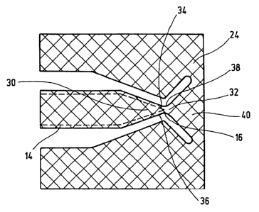
In order to avoid this the etching mask 24 according to the invention has a
shaping
area 30 for the tip 16 to be formed and a distal - with regard to the lancing
direction -
adjoining screening area 32 preventing the front of the tip 16 from being
etched off.
The shaping area 30 narrows towards the screening area 32 and the side flanks
34, 36
of the mask 24 are bevelled with a linear slope. Starting at a constriction 38
the


CA 02592310 2010-11-04

-9-
screening area 32 widens while forming a bridge section 40 towards the other
areas of
the mask so that the etching mask 24 remains overall more stable.

Hence, a sharp tip 16 is etched free by lateral undercutting of the side
flanks 34, 36 of
the shaping area and screening area 30, 32, the contour of which is shown by
the
dashed line in fig. 2. In this connection the screening area 32 has a larger
screening
length than the undercutting width viewed in the proximal direction whereas
the width
of the constriction 38 is less than twice the lateral undercutting width. In
this manner
the etched away material fronts converge at the constriction 38 until finally
the tip 16
is uncovered when the etching process is completed.

The front side section of the mask 24 shown in fig. 3 is designed to be
complementary
to the desired capillary structure 18 in the area of the lancing member 14.
Accordingly
the mask 24 has a capillary slot 42 through which the channel 18 is etched in
to form
the channel walls 44. In order to also facilitate the lancing in this case the
distal ends
of the channel walls 44 are chamfered as sharp tips 16'. This is achieved in
the manner
described above by screening areas 32 positioned in front where in fig. 3
functionally
identical parts have the same reference numerals so that reference can be made
to the
previous embodiments. In contrast to fig. 2 the side flanks 34, 36 in the area
of the
constriction 38 are not concavely curved on both sides but are rather bluntly
angled on
one side and on the opposite side thereto they are linearly delimited by the
capillary

gap 42 so that a wedge-shaped tip 16' is formed as shown by the dashed line.

The basic geometric effects of the etching process in the area of the channel
tips 16'
are illustrated in figs. 4 to 6. Figs 5 and 6 only show the upper substrate
area after a
certain etching time where the lateral etching contours 46 only describe a
circular line
in the case of an isotropic etching action. Thus lateral undercutting of the
mask edges

and side flanks 34, 36 of the mask 24 result in undercut edges of the shaped
member


CA 02592310 2010-11-04

- 10-

48, 50 as shown best in fig. 5. Such undercuts are indeed desirable in the
area of the
capillary channel 18 because they further improve the capillarity. However,
the
undercut 52 results in a barb (fig. 6) at the tip 16, 16' which can impair the
lancing
into the skin.

In order to rectify this, a compensation slot 54 can be kept free in the mask
24
according to figs. 7 and 8. This slot extends at a lateral distance to an
undercut edge
section 56 in the shaping area 30 of the mask 24 and ensures that the edges of
the
undercut 48 that would otherwise be formed are etched away. Hence, the etching
agent which penetrates near to the edge via the compensation slot 54 results
in a

rounding of the edge 58 while avoiding a barb. The width of the mask strip 60
between the mask edge 56 and the compensation slot 54 is advantageously less
than
the lateral undercut width. This should ensure that the compensation slot 54
has a
substantially smaller inner width compared to the neighbouring mask cut-out 62
so
that the rounded edges 58 have a correspondingly smaller etching radius.

Representative Drawing
A single figure which represents the drawing illustrating the invention.
Administrative Status

For a clearer understanding of the status of the application/patent presented on this page, the site Disclaimer , as well as the definitions for Patent , Administrative Status , Maintenance Fee  and Payment History  should be consulted.

Administrative Status

Title Date
Forecasted Issue Date 2011-10-18
(86) PCT Filing Date 2005-12-10
(87) PCT Publication Date 2006-06-29
(85) National Entry 2007-06-15
Examination Requested 2007-09-24
(45) Issued 2011-10-18
Deemed Expired 2021-12-10

Abandonment History

There is no abandonment history.

Payment History

Fee Type Anniversary Year Due Date Amount Paid Paid Date
Application Fee $400.00 2007-06-15
Maintenance Fee - Application - New Act 2 2007-12-10 $100.00 2007-06-15
Request for Examination $800.00 2007-09-24
Maintenance Fee - Application - New Act 3 2008-12-10 $100.00 2008-10-29
Maintenance Fee - Application - New Act 4 2009-12-10 $100.00 2009-10-13
Maintenance Fee - Application - New Act 5 2010-12-10 $200.00 2010-11-25
Final Fee $300.00 2011-07-27
Maintenance Fee - Patent - New Act 6 2011-12-12 $200.00 2011-11-16
Maintenance Fee - Patent - New Act 7 2012-12-10 $200.00 2012-11-15
Maintenance Fee - Patent - New Act 8 2013-12-10 $200.00 2013-11-14
Maintenance Fee - Patent - New Act 9 2014-12-10 $200.00 2014-11-14
Maintenance Fee - Patent - New Act 10 2015-12-10 $250.00 2015-11-13
Maintenance Fee - Patent - New Act 11 2016-12-12 $250.00 2016-11-10
Maintenance Fee - Patent - New Act 12 2017-12-11 $250.00 2017-11-14
Maintenance Fee - Patent - New Act 13 2018-12-10 $250.00 2018-11-15
Maintenance Fee - Patent - New Act 14 2019-12-10 $250.00 2019-11-19
Maintenance Fee - Patent - New Act 15 2020-12-10 $450.00 2020-11-12
Owners on Record

Note: Records showing the ownership history in alphabetical order.

Current Owners on Record
F. HOFFMANN-LA ROCHE AG
Past Owners on Record
GRISS, PATRICK
LOPEZ, ANGEL
ZIPFEL, MARZELLINUS
Past Owners that do not appear in the "Owners on Record" listing will appear in other documentation within the application.
Documents

To view selected files, please enter reCAPTCHA code :


To view images, click a link in the Document Description column. To download the documents, select one or more checkboxes in the first column and then click the "Download Selected in PDF format (Zip Archive)" or the "Download Selected as Single PDF" button.

List of published and non-published patent-specific documents on the CPD .

If you have any difficulty accessing content, you can call the Client Service Centre at 1-866-997-1936 or send them an e-mail at CIPO Client Service Centre.


Document
Description 
Date
(yyyy-mm-dd) 
Number of pages   Size of Image (KB) 
Claims 2011-02-15 5 154
Claims 2010-11-04 5 148
Description 2010-11-04 10 388
Abstract 2007-06-15 1 17
Claims 2007-06-15 4 142
Drawings 2007-06-15 4 101
Description 2007-06-15 9 359
Representative Drawing 2007-09-05 1 16
Cover Page 2007-09-06 2 53
Cover Page 2011-09-15 1 50
Abstract 2011-05-16 1 17
Prosecution-Amendment 2011-02-15 5 176
Correspondence 2007-09-04 1 25
PCT 2007-06-15 7 244
Assignment 2007-06-15 4 139
Correspondence 2007-09-06 2 53
Prosecution-Amendment 2007-09-24 1 42
PCT 2007-06-16 10 420
Prosecution-Amendment 2008-02-05 1 28
Correspondence 2011-07-27 2 62
Prosecution-Amendment 2010-06-15 2 42
Prosecution-Amendment 2010-11-04 18 625
Prosecution-Amendment 2011-01-27 1 40