Language selection

Search

Patent 2592356 Summary

Third-party information liability

Some of the information on this Web page has been provided by external sources. The Government of Canada is not responsible for the accuracy, reliability or currency of the information supplied by external sources. Users wishing to rely upon this information should consult directly with the source of the information. Content provided by external sources is not subject to official languages, privacy and accessibility requirements.

Claims and Abstract availability

Any discrepancies in the text and image of the Claims and Abstract are due to differing posting times. Text of the Claims and Abstract are posted:

  • At the time the application is open to public inspection;
  • At the time of issue of the patent (grant).
(12) Patent: (11) CA 2592356
(54) English Title: AIRCRAFT INTERIOR EQUIPMENT SUPPORT
(54) French Title: PORTE-EQUIPEMENT D'AMENAGEMENT INTERIEUR D'AERONEF
Status: Deemed expired
Bibliographic Data
(51) International Patent Classification (IPC):
  • B64D 11/00 (2006.01)
  • B64D 11/06 (2006.01)
  • F16M 11/08 (2006.01)
(72) Inventors :
  • KENNEDY, OTHAR P. (United States of America)
(73) Owners :
  • AMI INDUSTRIES, INC. (United States of America)
(71) Applicants :
  • AMI INDUSTRIES, INC. (United States of America)
(74) Agent: BERESKIN & PARR LLP/S.E.N.C.R.L.,S.R.L.
(74) Associate agent:
(45) Issued: 2012-01-17
(22) Filed Date: 2007-06-20
(41) Open to Public Inspection: 2008-02-14
Examination requested: 2007-12-19
Availability of licence: N/A
(25) Language of filing: English

Patent Cooperation Treaty (PCT): No

(30) Application Priority Data:
Application No. Country/Territory Date
60/837,671 United States of America 2006-08-14
11/761,854 United States of America 2007-06-12

Abstracts

English Abstract

A equipment support for aircraft and the like comprises a base to which a lower link, an intermediate link, and a equipment platform are attached. The lower link rotates horizontally about the base. The intermediate link rotates horizontally about the end of the lower link and the equipment platform rotates horizontally about the end of the intermediate link. This arrangement gives the equipment platform the ability to assume an infinite number of lateral positions and 360 degrees of rotation. The equipment support is locked in position by means of locking pins that engage corresponding metering plates adjacent the support bearings. The locking pins are released by a common linkage that sequentially releases the equipment platform rotation lock then simultaneously releases the rotation locks of the intermediate and lower links.


French Abstract

Le porte-équipement d'aéronef, etc. comprend une base à laquelle un lien inférieur, un lien intermédiaire et une plate-forme d'équipement sont fixés. Le lien inférieur tourne horizontalement sur la base. Le lien intermédiaire tourne horizontalement sur l'extrémité du lien inférieur et la plate-forme d'équipement tourne horizontalement sur l'extrémité du lien intermédiaire. Cette disposition confère à la plate-forme d'équipement la capacité de prendre un nombre infini de positions latérales et de tourner sur 360 degrés. Le porte-équipement est bloqué en position au moyen de tiges de blocage qui entrent en contact avec des plaques de mesure correspondantes adjacentes aux roulements du porte-équipement. Les tiges de blocage sont libérées par une tringlerie commune qui séquentiellement libère le verrou de rotation de la plate-forme de l'équipement puis libère simultanément les verrous de rotation des liens intermédiaire et inférieur.

Claims

Note: Claims are shown in the official language in which they were submitted.


WHAT IS CLAIMED IS:


1. A support for securing aircraft interior equipment to a frame comprising:
a base adapted to be attached to said frame;

a lower link having a fixed end and a free end, said fixed end of said lower
link
comprising a first rotating joint defining a first axis of rotation about a
point fixed on said
base, said free end of said lower link extending radially outward from said
first axis of
rotation;

an intermediate link having a fixed end and a free end, said fixed end of said

intermediate link comprising a second rotating joint defining a second axis of
rotation about a
point fixed on said free end of lower link, said free end of said intermediate
link extending
radially outward from said second axis of rotation;

an equipment platform attached to said interior equipment, said equipment
platform
having a third rotating joint defining a third axis of rotation about a point
fixed on said free
end of said intermediate link;

a first rotation lock coupled to said lower link, said first rotation lock
being moveable
from a disengaged position to an engaged position for engaging said base to
prevent rotation
of said lower link about said base, said first rotation lock engaging said
base at a contact point
located substantially on said second axis of rotation;

a second rotation lock coupled to said intermediate link, said second rotation
lock
being moveable from a disengaged position to an engaged position for engaging
said lower
link to prevent rotation of said intermediate link about said lower link, said
second rotation


9


lock engaging said lower link at a contact point located substantially on said
third axis of
rotation; and

an actuator moveable from a first position to a second position, said actuator
coupled
to said first rotation lock and said second rotation lock for moving said
first rotation lock and
said second rotation lock from their engaged positions into their disengaged
positions.


2. The support of claim 1, wherein:

said second axis of rotation is parallel to said first axis of rotation

3. The support of claim 2, wherein:

said third axis of rotation is parallel to said second axis of rotation.

4. The support of claim 1, wherein:

said actuator moves said first rotation lock and said second rotation lock
simultaneously from their engaged positions into their disengaged positions as
said actuator is
moved from the first position to the second position.


5. The support of claim 1, further comprising:

a third rotation lock coupled to said equipment platform, said third rotation
lock being
moveable from a disengaged position to an engaged position for engaging said
intermediate to
prevent rotation of said equipment platform about said intermediate link.


6. The support of claim 5, wherein:

said third rotation lock engages said intermediate link at a contact point
offset from
said third axis of rotation.


7. The support of claim 5, wherein:

said actuator is coupled to said third rotation lock and is moveable to an
intermediate
position for moving said third rotation lock from the engaged position to the
disengaged
position.


8. The support of claim 7, wherein:

said actuator moves said first rotation lock and said second rotation lock
simultaneously from their engaged positions into their disengaged positions as
said actuator is
moved from the intermediate position to the second position.


9. The support of claim 1, wherein:

said first rotation lock comprises a spring-loaded pin for engaging a
plurality of holes
formed in said base, said spring-loaded pin having a longitudinal axis
coinciding with said
second rotational axis; and

said second rotational lock comprises a spring-loaded pin for engaging a
plurality of
holes formed in said lower link, said spring-loaded pin having a longitudinal
axis coinciding
with said third rotational axis.


11


10. The support of claim 1, further comprising:

an aircraft seat attached to said equipment platform.

11. The support of claim 1, further comprising:

a table attached to said equipment platform.


12. A support for securing aircraft equipment to an aircraft frame comprising:

a base adapted to be attached to said aircraft frame;

a lower link, said lower link comprising an elongate member having a first end
and a
second end;

a first rotational bearing operatively disposed between the first end of said
lower link
and said base said first rotational bearing defining a first rotational axis;

an intermediate link, said intermediate link comprising an elongate member
having a
first end and a second end;

a second rotational bearing operatively disposed between the first end of said

intermediate link and the second end of said lower link, said second
rotational bearing
defining a second rotational axis parallel to and offset from said first
rotational axis;

an equipment platform adapted to be attached to said aircraft equipment;

a third rotational bearing operatively disposed between said equipment
platform and
the second end of said intermediate link, said third rotational bearing
defining a third
rotational axis parallel to and offset from said second rotational axis;


12


first locking means, said first locking means moveable from an unlocked
position to a
locked position for preventing rotation of said first rotational bearing; and

second locking means, said second locking means moveable from an unlocked
position to a locked position for preventing rotation of said second
rotational bearing, said
first and second locking means being moveable simultaneously from a locked
position to an
unlocked position by a shared linkage.


13. The support of claim 12, further comprising:

third locking means, said third locking means moveable from an unlocked
position to
a locked position for preventing rotation of said third rotational bearing,
said third locking
means being moveable from a locked position to an unlocked position by said
shared linkage.

14. The support of claim 13, wherein:

said shared linkage comprises a moveable control arm slidably attached to said

intermediate link.


15. The support of claim 14, wherein:

said shared linkage is moveable from a first position in which said first,
second, and
third locking means are in their locked positions respectively, to a second
position in which
said first and second locking means are in their locked positions and said
third locking means
is in its unlocked position, said shared linkage further moveable to a third
position in which
said first, second and third locking means are in their unlocked positions.


13


16. The support of claim 15, further comprising:

an operating lever pivotally attached to said equipment platform, said
operating lever
operatively attached to said third rotational lock and further comprising a
push rod for moving
said moveable control arm, said push rod having a line of action coinciding
with said third
rotational axis.


17. The support of claim 13, wherein:

said first rotation lock comprises a spring-loaded pin for engaging a
plurality of holes
formed in said base, said spring-loaded pin having a longitudinal axis
coinciding with said
second rotational axis; and

said second rotational lock comprises a spring-loaded pin for engaging a
plurality of
holes formed in said lower link, said spring-loaded pin having a longitudinal
axis coinciding
with said third rotational axis.


18. The support of claim 17, wherein:

said third rotation lock comprises a spring-loaded pin for engaging a
plurality of holes
formed in said intermediate link, said spring-loaded pin having a longitudinal
axis offset from
said third rotational axis.


19. The support of claim 12, further comprising:
a seat attached to said equipment platform

14


20. The support of claim 12, further comprising:
a table attached to said equipment platform


Description

Note: Descriptions are shown in the official language in which they were submitted.


CA 02592356 2011-03-01

AIRCRAFT INTERIOR EQUIPMENT SUPPORT
[0011 Blank

BACKGROUND OF THE INVENTION

[0021 The present invention relates to adjustable supports for aircraft
interior
equipment, in particular supports for aircraft seating, tables and the like.

[0031 A need exists in many aircraft interiors for seats and tables to
translate and/or
rotate for passenger comfort. Many aircraft floor space plans require several
degrees of
motion to allow a bulky seat or coffee table to be moved in the tight confines
of smaller
business aircraft. Seats must often be movable toward or away from tables,
desks and other
seats, all without using up valuable floor space. Military aircraft often have
a need to access
multiple stations from a single seat. In each of these cases, however, a
chosen locked position
must securely support and protect the seat occupant for normal use, turbulence
loads and hard
landing loads.

[0041 U.S. Patent No. 4,671,572 (hereinafter "the '572 patent") discloses an
adjustable
chair having a chair post that is movable within a large aperture in the
mounting frame. This
arrangement allows the chair to be rotated and translated across the top of
the chair mounting
frame. The chair is fixed in a desired position by a friction brake that
engages the underside
of the chair mounting frame. A disadvantage of the chair disclosed in the '572
patent is the
substantial volume and floor space occupied by the relatively bulky chair
mounting frame.
I


CA 02592356 2007-06-20

Additionally, the friction lock does not provide a positive locking feature to
endure heavy side
loads.

SUMMARY OF THE INVENTION

[0051 The present invention comprises a support for securing interior
equipment such as
seats and tables to a frame such as for securing an aircraft seat to the floor
of an aircraft.
According to an illustrative embodiment, the support comprises a base that is
attached to the
aircraft floor. The base supports a lower support thrust bearing. A lower link
is attached at one
end to the support bearing so that the link is capable of rotating about the
base. The other end of
the link has a bearing that supports a second, intermediate link so that the
intermediate link
rotates about the end of the lower link. The opposite end of the intermediate
link has a bearing
that supports the seat platform, which enables the seat platform to rotate
about the end of the
intermediate link. This arrangement of links allows the seat frame to be moved
laterally in any
direction and the seat frame to be rotated 360 degrees.

[0061 In the illustrative embodiment, the support is locked in position by
means of
locking pins that engage corresponding metering plates adjacent the support
bearings. The
locking pins are released by a common linkage that sequentially releases the
seat rotation lock
then simultaneously releases the rotation locks of the intermediate and lower
links. The
simultaneous release of the intermediate and lower locks is effected by a
movable yoke that is
attached to the intermediate link. Although the yoke is attached to the
intermediate link, the
mechanism does not bind the lower and intermediate links or the seat platform
from rotating in
the released position because each locking pin engages its corresponding
metering plate at a
contact point located substantially on the same axis as the support bearing
immediately above.
2


CA 02592356 2007-06-20

Thus the lower link rotation lock engages its metering plate substantially
along the rotational
axis defined by the bearing that supports the intermediate link and the
intermediate link rotation
lock engages its metering plate substantially along the rotational axis of the
bearing that supports
the seat platform. The locking and release mechanism thus permits full
translation and rotation
of the seat platform while providing for a solid, positive lock of the seat
platform once the locks
are engaged.

BRIEF DESCRIPTION OF THE DRAWING

[007] The present invention will be better understood from a reading of the
following
detailed description, taken in conjunction with the accompanying drawing
figures in which
like references designate like elements and, in which:

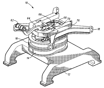
10081 FIG. I is a front perspective view of an illustrative embodiment of a
seat
platform incorporating features of the present invention;

10091 FIG. 2 is a front perspective view of the illustrative seat platform in
its
forwardmost extended position;

[0010] FIG. 3 is a front perspective view of the illustrative seat platform in
a partially
extended position;

100111 FIG. 4 is a front perspective view of the illustrative seat platform in
a partially
extended and rotated position;

[0012] FIG. 5 is an exploded perspective view of portions of the links and
seat platform
of the illustrative seat support;

100131 FIG. 6 is a cross-sectional view of the illustrative seat support with
the rotation
locks in their fully engaged position;

3


CA 02592356 2007-06-20

100141 FIG. 7 is a cross-sectional view of the illustrative seat support with
the seat
rotation lock disengaged;

[00151 FIG. 8 is a cross-sectional view of the illustrative seat support with
the seat
rotation and link rotation locks disengaged and the seat platform moved to its
forwardmost
extended position; and

[00161 FIG. 9 is a perspective view of the rotation lock actuator linkage.
DETAILED DESCRIPTION

[00171 The drawing figures are intended to illustrate to the general manner of
construction and are not necessarily to scale. In the detailed description and
in the drawing
figures, specific illustrative examples are shown and herein described in
detail. It should be
understood, however, that the drawing figures and detailed description are not
intended to
limit the invention to the particular form disclosed, but are merely
illustrative and intended to
teach one of ordinary skill how to make and/or use the invention claimed
herein and for
setting forth the best mode for carrying out the invention.

[00181 With reference to the figures and in particular Figs. 1-5, seat support
10
comprises a base 12 a lower link 14 an intermediate link 16 and a seat
platform 18. Lower
link 14 is supported at its fixed end 20 by a lower thrust collar assembly 22
consisting of a
spigot flange 24 and a roller thrust bearing 26. The flanged portion 28 of
spigot flange 24 has
a plurality of holes 30 formed therein to form a metering plate 32, the
function of which will
be explained in greater detailed hereafter. A retainer assembly 34 consisting
of a second roller
thrust bearing 36 and a collar 38 retains lower link 14 to the spigot portion
40 of spigot flange
24.

4


CA 02592356 2007-06-20

[0019] The free end 44 of lower link 14 supports the fixed end 42 of
intermediate link
16 by means of an intermediate thrust collar assembly 46 attached to free end
44 of lower link
14. Intermediate thrust collar assembly 46 includes a metering plate 32a with
a plurality of
holes 30a and is identical in construction to thrust collar assembly 22 and
therefore will not be
explained further herein. Intermediate link 16 is retained on intermediate
thrust collar
assembly 46 by a retainer assembly 48, which is identical in construction and
operation to
retainer assembly 34 and therefore will not be explained in detail herein.

[0020] Seat platform 18 is secured to the free end 50 of intermediate link 16
by an upper
thrust collar assembly 52, which is attached to the free end 50 of
intermediate link 16. Upper
thrust collar assembly 52 includes a metering plate 32b having a plurality of
holes 30b and is
identical in construction and operation as thrust collar assembly 22 and
therefore will not be
explained further herein. Seat platform 18 is retained to thrust collar
assembly 52 by a
retainer assembly 54, which is identical in construction and operation to
retainer assembly 34.
[0021] As can be determined from the foregoing, the arrangement of bearings
and links
enable seat platform 18 to be located anywhere from directly over the
centerline of the
rotating joint defined by thrust collar assembly 22 as shown in Fig. 1 to a
fully forward
extended position as shown in Fig. 2, to a partially forward position as shown
in Fig. 3, to a
partially forward and rotated position as shown in Fig. 4, or any number of
intermediate,
rotated and unrotated positions enabled by the two degrees of freedom inherent
in the
arrangement of links and rotating joints.

[0022] With further reference to Figs. 6-9, lower link 14, intermediate link
16 and seat
platform 18 are locked in position by seat locking pin 78, intermediate
locking pin 86 and


CA 02592356 2007-06-20

lower locking pin 88, each of which is spring-loaded to engage a corresponding
hole 30, 30a,
30b in metering plates 32, 32a, 32b. Lower link 14, intermediate link 16 and
seat platform 18
are released for rotation/translation then locked into position by means of a
locking and
release mechanism 60 which consists of a handle 62, an arm 64 an upper walking
beam 66, a
push rod 68, a lower walking beam 70 and a yoke 72. Upper walking beam 66 is
supported by
upper axle 74 which rotates in corresponding recesses formed in control lever
mount 76 (Figs.
1-4). As handle 62 is pulled upward, upper walking beam 66 simultaneously
lifts seat locking
pin 78 against its spring so that it disengages corresponding hole 30b of
metering plate 32b.
Simultaneously, upper walking beam 66 presses push rod 68 into socket 80 of
lower walking
beam 70. As can be seen most clearly in Figs. 6-7, there is positive
engagement between
upper walking beam 66 and seat locking pin 78 so that lifting handle 62 causes
seat locking
pin 78 to immediately disengage metering plate 32b to allow the seat to
rotate. However,
there is clearance between push rod 68 and the bottom of socket 80 of lower
walking beam 70.
Therefore, lower walking beam 70 does not move immediately. As handle 62 is
pulled further
upward, however, push rod 68 engages the lower surface of socket 80 causing
lower walking
beam 70 to pivot about its lower axle 82, which in turn lifts yoke 72 via link
84.

100231 Yoke 72 is constrained to move vertically under the urging of link 84
by means
of rollers 90, 92 mounted to saddles 94, 96 each of which engage a
corresponding track 98
and 100 formed in yoke 72. As yoke 72 is lifted upward, it simultaneously
lifts intermediate
locking pin 86 and lower locking pin 88 to disengage pins 86 and 88 from
corresponding
holes 30 and 30a of metering plates 32 and 32a. With locking pins 86 sand 88
released, lower
6


CA 02592356 2007-06-20

link 14 and intermediate link 16 are free to rotate about their respective
thrust collar
assemblies 22 and 46, thereby enabling horizontal translation of seat platform
18.

100241 As noted hereinbefore, yoke 72 lifts intermediate locking pin 86 and
lower
locking pin 88 simultaneously so that each disengages its respective metering
plate at the
same time, however, in an alternative embodiment, yoke 72 disengages
intermediate locking
pin 86 and lower locking pin 88 sequentially. As can be seen most clearly in
Fig. 8, lower
locking pin 88 engages metering plate 32 at a point that is located
substantially on the axis of
rotation 102 that is defined by intermediate thrust collar assembly 46. Thus
even with lower
locking pin 88 engaged to metering plate 32, intermediate link 16 can still
rotate about
intermediate thrust collar assembly 46 as long as intermediate locking pin 86
is disengaged.
Intermediate link 16 simply pivots about lower locking pin 88 in its engaged
position.
Similarly, intermediate locking pin 86 engages metering plate 32a at a point
that lies
substantially on the axis of rotation 104 defined by upper thrust collar
assembly 52. This
enables seat platform 18 to rotate about upper thrust collar assembly 52 as
long as seat locking
pin 78 is disengaged from metering plate 32b.

[00251 In the illustrative embodiment, lower locking pin 88 has a head portion
108 that
rotates in a seat (not shown) in yoke 72 to enable yoke 72, which is mounted
to intermediate
link 16 to freely rotate about engaged lower locking pin 88. Alternatively,
since lower locking
pin is cylindrical in shape, it would be possible simply to allow lower
locking pin 88 to rotate
in hole 30 formed in metering plate 32. Similarly, intermediate locking pin 86
has a head
portion 110 that rotates in a seat formed in yoke 72 to enable seat platform
18 to rotate about
engaged intermediate locking pin 86. Because the illustrative seat support 10
has only two
7


CA 02592356 2007-06-20

main links in addition to the seat platform, the longitudinal axis 106 of seat
locking pin 78 is
merely offset from axis 104 of upper thrust collar assembly 52, there being no
additional
thrust collar assemblies mounted above.

[00261 As can be determined from the foregoing, the unique arrangement of
links and
the alignment of the locking pins with the axis of rotation of the thrust
collar assemblies
immediately above enables a common rigid linkage such as yoke 72 to positively
disengage
and engage the locking pins without impeding free rotation of lower link 14,
intermediate link
16 and seat platform 18 and without the use of flexible joints, cables or
other cumbersome
mechanisms.

100271 Although certain illustrative embodiments and methods have been
disclosed
herein, it will be apparent from the foregoing disclosure to those skilled in
the art that
variations and modifications of such embodiments and methods may be made
without
departing from the spirit and scope of the invention. For example, although in
the illustrative
embodiment the support is for securing a seat to an aircraft floor, the
invention is equally
capable of securing other interior equipment, such as a coffee table, to a
vehicle frame.
Additionally, although the illustrative embodiment has only two main links, a
seat supported
by three or more links is considered within the scope of the invention.
Accordingly, it is
intended that the invention shall be limited only to the extent required by
the appended claims
and the rules and principles of applicable law.

8

Representative Drawing
A single figure which represents the drawing illustrating the invention.
Administrative Status

For a clearer understanding of the status of the application/patent presented on this page, the site Disclaimer , as well as the definitions for Patent , Administrative Status , Maintenance Fee  and Payment History  should be consulted.

Administrative Status

Title Date
Forecasted Issue Date 2012-01-17
(22) Filed 2007-06-20
Examination Requested 2007-12-19
(41) Open to Public Inspection 2008-02-14
(45) Issued 2012-01-17
Deemed Expired 2015-06-22

Abandonment History

There is no abandonment history.

Payment History

Fee Type Anniversary Year Due Date Amount Paid Paid Date
Application Fee $400.00 2007-06-20
Request for Examination $800.00 2007-12-19
Maintenance Fee - Application - New Act 2 2009-06-22 $100.00 2009-06-12
Maintenance Fee - Application - New Act 3 2010-06-21 $100.00 2010-06-16
Maintenance Fee - Application - New Act 4 2011-06-20 $100.00 2011-06-06
Final Fee $300.00 2011-11-02
Maintenance Fee - Patent - New Act 5 2012-06-20 $200.00 2012-05-30
Maintenance Fee - Patent - New Act 6 2013-06-20 $200.00 2013-05-08
Owners on Record

Note: Records showing the ownership history in alphabetical order.

Current Owners on Record
AMI INDUSTRIES, INC.
Past Owners on Record
KENNEDY, OTHAR P.
Past Owners that do not appear in the "Owners on Record" listing will appear in other documentation within the application.
Documents

To view selected files, please enter reCAPTCHA code :


To view images, click a link in the Document Description column. To download the documents, select one or more checkboxes in the first column and then click the "Download Selected in PDF format (Zip Archive)" or the "Download Selected as Single PDF" button.

List of published and non-published patent-specific documents on the CPD .

If you have any difficulty accessing content, you can call the Client Service Centre at 1-866-997-1936 or send them an e-mail at CIPO Client Service Centre.


Document
Description 
Date
(yyyy-mm-dd) 
Number of pages   Size of Image (KB) 
Abstract 2007-06-20 1 21
Description 2007-06-20 8 326
Claims 2007-06-20 7 184
Drawings 2007-06-20 8 220
Representative Drawing 2008-01-21 1 21
Cover Page 2008-02-04 1 53
Description 2011-03-01 8 323
Cover Page 2011-12-15 2 59
Assignment 2007-06-20 3 87
Prosecution-Amendment 2007-12-19 1 28
Fees 2009-06-12 1 201
Prosecution-Amendment 2009-11-25 1 34
Fees 2010-06-16 1 201
Prosecution-Amendment 2010-12-20 1 33
Correspondence 2010-12-29 1 12
Prosecution-Amendment 2011-01-06 1 31
Prosecution-Amendment 2011-03-01 3 80
Correspondence 2011-01-14 3 114
Fees 2011-06-06 1 202
Prosecution Correspondence 2008-01-15 1 40
Correspondence 2011-11-02 1 40