Note: Descriptions are shown in the official language in which they were submitted.
CA 02592359 2007-06-20
1
ADJUSTABLE WEIR FOR HYDROELECTRIC DAM INSTALLATIONS
TECHNICAL FIELD
This invention relates to dam installations for hydroelectric power
generation.
More particularly, this invention relates to controlling the flow of water
through turbines
in hydroelectric dam installations.
BACKGROUND ART
The driving power for a hydroelectric generation installation typically
comprises a
reservoir of water created by the construction of a dam across a river or
other waterway
system, at least one electric generator driven by a turbine receiving a
channeled flow of
headwater from the reservoir, and a downstream discharge system for egress of
spent
water from the turbine back into the river or waterway system. The amount of
electricity
generated in such installations is directly affected by the height of the
water in the dam at
the water intake stand pipe that feeds the penstock delivering the water to
the turbine. In
general terms, increasing the height of a dam during construction enables the
installation
of a taller water intake stand pipe thereby enabling the delivery of a taller
column of
water to the turbine. The bottom of the water column is typically defined by
the bottom
surface of the reservoir. It is the pressure caused by weight of the volume of
water during
its vertical drop from top to the bottom of the column that determines the
force with
which the turbine is driven. Turbines are commonly situated at or near the
bottom of the
water column. The vertical drop of water provided to the turbine is commonly
referred to
as the "head" of the dam. The water pressure delivered to the turbine can be
manipulated
by the diameters selected for the intake stand pipe and the penstock, and by
the height at
which the water inlets into the intake stand pipe are positioned relative to
the turbine to
which the water is delivered. Maintenance of adequate volumes of water in dam
reservoirs is dependent on the rate of water flow in the upstream waterway
feeding into
the dam, and on the annual precipitation in the forms of rain, snow and
snowmelt that
supply water into the upstream waterway. Extended periods of peak power
production are
accompanied by high discharge volumes of spent water from the dam tailraces
into the
DM VAN/265880-00003/6696299.2
CA 02592359 2007-06-20
2
tailrace pools adjacent the dam often result in the downstream water levels in
the tailrace
pools rising above the levels of the turbine installation thereby directly
causing a decrease
in power production. Those skilled in these arts understand that the distance
of the water
column from the uppermost intake of the stand pipe to the downstream water
level in the
tailrace pool adjacent the dam, where backpressure becomes effective is known
as the
"net head" of the dam and that the "net head" is the primary determinant of
the driving
force delivered to the turbine and therefore, the height of the "net head"
directly affects
hydroelectric power generation. Multiple vertically positioned water inlets
are provided
on individual stand pipes to enable delivery of water to the turbine when the
water level
in reservoir drops during periods of extended dry and/or drought conditions.
However, it
is known by those skilled in these arts that the levels of impounded water
maintained in a
hydroelectric dam reservoir are directly affected by power production by the
dam, i.e., by
the rates of water removal from the reservoir and delivery to the turbines.
Another problem associated with hydroelectric power generation during periods
of low power generation when the turbines are idling, or during extended dry
or drought
periods, is that reduction of water pressure into the turbine results in a
lower volume of
water egress from the tailrace into the downstream waterway. A common
consequence is
that the water levels in the downstream water decline to the point where a
portion or all
of the tailrace is exposed to the atmosphere thereby allowing air to ingress
into the
turbine via the tailrace infrastructure, predisposing the turbine to
cavitation within the
water delivery-egress infrastructure. The high-speed rotation of the turbine
blades
intermixes the air from the tailrace with the ingressing headwater from the
reservoir
causing a plurality of localized intense low-pressure regions (i.e., vacuum
pressure)
comprising air bubbles swirling about the turbine blades and shaft. The
bubbles tend to
collapse violently sending out shock waves that physically impact surround
solid
surfaces, initially causing minor damage in the form of pits and abrasions in
the blade
surfaces that over extended periods or episodes of cavitation, may increase in
size to form
voids within the blades and to cause fatigue in the materials used to
configure the blades
and the turbine shaft. Such damaged turbines must be replaced to prevent
serious
equipment malfunctions and breakdowns which may incapacitate the hydroelectric
generating plant until repairs are made.
DM VAN/265880-00003/6696299.2
CA 02592359 2007-06-20
3
The prior art discloses several strategies for increasing the effective head
of a dam
without having to increase the height of the dam and for controlling the level
of water in
a tailrace in response to seasonal water flow fluctuations upstream of the
dam. U.S.
Patent No. 4,014,173 discloses installing a generator-driving turbine in a
water-tight pit
that is substantially below the bed level of the tail water and continuously
removing water
discharged from the turbine by a self-energizing impulse pump known to those
skilled in
these arts as a hydraulic ram. The hydraulic ram is preferably installed in a
second water-
tight pit located downstream from the turbine pit and must be interconnected
to the
turbine pit by an underground piping infrastructure. The complex construction
required
by the` 173 system not suitable for many landscapes which are suitable for
installation of
hydroelectric power generation stations; furthermore, this system is difficult
to retrofit to
existing hydroelectric generating installations. Furthermore, the design and
the
configuration of the turbine and hydraulic ram pits impose restrictions on
ease-of-access
for maintenance, repair and replacement work. GB 700,320 discloses an
adjustable weir
installed in the tailrace of a hydraulic turbine during construction of the
hydroelectric
generating dam for the purpose of maintaining a level of water in tailrace
sufficiently
high so as to prevent cavitation at the turbine. The adjustable weir is
automatically
controlled by a device responsive to the water level in the tailrace in such a
manner that
the weir is kept below and out of the flow of water egressing from the turbine
as long as
the water level does not drop below a pre-determined minimum level. If the
water flow
does drop below the minimum level, then the adjustable weir is raised to dam
up the
water in the tailrace thereby raising the water level above the minimum
required to
prevent cavitation. The `320 adjustable weir is designed to be continually
submerged in
the tailrace water flow and consequently is subject to numerous operational
problems
including: (1) propensity for failure of individual components of the
adjustable weir or of
the unit itself as a consequence of wear and corrosion from being continually
submerged,
(2) difficulty of access for under-water maintenance and repair, and (3) the
`320 weir is
not debris-tolerant, i.e., any back-washed bottom scour such as rocks, tree
limbs and
other water-logged debris will jam against the weir and interfere with its
operation.
DM VAN/265880-00003/6696299.2
CA 02592359 2007-06-20
4
DISCLOSURE OF THE INVENTION
The exemplary embodiments of the present invention are directed to systems,
apparatus and methods for controllably manipulating and/or adjusting and/or
maintaining
the upstream and/or levels in artificially lowered downstream tail race water
courses in
hydroelectric dam installations so that maximum achievable net heads may be
maintained
regardless of changes in upstream impounded water levels.
According to one exemplary embodiment of the present invention, there is
provided a controllably adjustable weir device for installation into a
downstream
waterway communicating with a hydroelectric dam. The adjustable weir device is
configured for retractably communicating with and engaging spent water
discharged from
the dam's tailrace(s). When in a fully retracted position, the adjustable weir
device is in
minimal communication with spent water discharged for the dam tailraces. It is
preferable that, when in a fully retracted position, the weir device is not in
communication with discharged spent water. When in a fully engaged position,
the
adjustable weir device directly impedes the downstream flow of discharged
spent water
thereby manipulably maintaining a selected water level adjacent the dam's
tailrace(s).
When in a partially engaged position, the adjustable weir device partially
impedes and
restricts the downstream flow of discharged spent water from the turbine
tailrace(s).
According to one aspect, there is provided a controllably adjustable weir
device
approximate the distal end of the tailrace pool area of a hydroelectric dam.
The adjustable
weir device comprises at least one controllably inflatable-deflatable bladder
tethered to at
least one pair of supporting structures, said supporting structures engaging
and
cooperating with the bottom of the downstream waterway. A plurality of
inflatable
bladders may be conjoined by a tether to extend across a downstream waterway
communicating with the tailraces of the hydroelectric dam, said plurality of
bladders held
in place by means of each bladder tethered to a pair of supporting structures.
The at least
one bladder is interconnected to and communicates with a controllable supply
of
compressed air provided for upon demand inflation and deflation.
Alternatively, the
adjustable weir device may comprise at least one controllably inflatable and
deflatable
assembly of conjoined bladder infrastructures contained within a supporting
framework
DM VAN/265880-00003/6696299.2
CA 02592359 2007-06-20
engaging and cooperating with the bottom surface of a downstream waterway.
Alternatively, the adjustable weir device may comprise a plurality of
conjoined bladder
infrastructure assemblies contained within a supporting framework extending
across the
downstream waterway, said supporting framework cooperating with the opposing
river
5 banks. A controllable supply of compressed air is provided for on-demand
inflation and
deflation of the conjoined bladder infrastructure assemblies.
According to another aspect, there is provided a controllable adjustable weir
device comprising a fixed-in-place construction of a concrete barrier wall
extending
across the downstream waterway. The concrete barrier wall is provided with a
plurality of
spaced-apart open-ended voids therethrough, said voids configured for hinged
and/or
sliding installation of gates. The gates are configured for sealing engaging
and
disengaging the concrete barrier walls. At least one controlling device is
provided for
communicating and cooperating with said gates for controllably engaging and
disengaging the gates from the concrete barrier wall.
According to another exemplary embodiment of the invention, there is provided
a
downstream excavation approximate the distal end of the tailrace pool area of
a
hydroelectric dam, for increasing the head of the dam. The proximal edge of
the
excavation is approximate the distal end of the tailrace pool area to preserve
the structural
integrity of the toe region of the dam base and the supporting terrestrial
substrate
underlying the dam base, said distance determinable by site-specific
topography and
geophysical attributes. The depth of the excavation is selectable, site-
specific and
additive to the height of the dam head thereby enabling delivery of increased
water
pressure from the upstream impounded water reservoir adjacent the dam, to the
turbines
for increased power generation capacity. In a suitable form, the excavation is
extendible
between and communicates with the opposing banks of the downstream waterway
communicating with the hydroelectric dam. Alternatively, the excavation may be
configured about the longitudinal axis of the downstream waterway and may not
extend
to the river banks. Alternatively, the excavation may communicate with one but
not the
other of the two opposing banks of the downstream waterway.
DM VAN/265880-00003/6696299.2
CA 02592359 2007-06-20
6
According to a suitable aspect, there is provided a method of precisely
increasing
the head of a hydroelectric dam by installing an excavation in the bed of a
downstream
waterway, said excavation approximate the distal end of the tailrace pool area
of the dam.
The height of the increased head is manipulable by selection of a suitable
depth for the
excavation determined by skilled person in this art, based on site-specific
topography and
geophsycial attributes
According to yet another exemplary embodiment of the present invention, there
is
provided a controllably adjustable weir device as described herein interposed
a
downstream excavation as described herein approximate the toe region of a
hydroelectric
dam.
According to a further exemplary embodiment, there is provided a method for
controlling the water level of discharged spent water adjacent the tailraces
of a
hydroelectric dam by increasing the controlled engagement of the adjustable
weir device
of the present invention with the spent water discharged downstream from the
dam's
tailraces as the flow rates of water into the upstream impounded water
reservoir decline,
and by decreasing the controlled engagement of the adjustable weir device when
the
upstream flow rates of water into the impounded water reservoir increase.
DESCRIPTION OF THE DRAWINGS
The present invention will be described in conjunction with reference to the
following
drawings, in which:
Fig. 1 is a cross-sectional side view of an exemplary prior art hydroelectric
dam
installation;
Fig. 2 is a cross-sectional side view of the hydroelectric dam installation
from Fig.
1, shown provided with an exemplary embodiment of the present invention;
Fig. 3 is a plan view of the hydroelectric dam installation shown in Fig. 2;
Fig. 4 is a cross-sectional side view of the hydroelectric dam installation
from Fig.
2, shown provided with an alternative exemplary embodiment of the present
invention;
DM VAN/265880-00003/6696299.2
CA 02592359 2007-06-20
7
Fig. 5 is a cross-sectional side view of the hydroelectric dam installation
from Fig.
2, shown provided with an exemplary embodiment of an inflatable weir according
to the
present invention, wherein the weir is shown in the deflated mode;
Fig. 6 is a cross-sectional side view of the hydroelectric dam installation
from Fig.
5, shown with the weir in the inflated mode;
Fig. 7 is a plan view of the embodiment shown in Fig. 6;
Fig. 8 is a cross-sectional side view of the hydroelectric dam installation
from Fig.
2, shown provided with an alternative exemplary embodiment of an inflatable
weir
according to the present invention, wherein the weir is shown in the deflated
mode;
Fig. 9 is a cross-sectional side view of the hydroelectric dam installation
from Fig.
5, shown with the weir in the inflated mode;
Fig. 10 is a plan view of the embodiment shown in Fig. 9;
Fig. 11 is a cross-sectional side view of the hydroelectric dam installation
from
Fig. 2, shown provided with an exemplary embodiment of an adjustable multi-
component
weir according to the present invention, wherein the weir components are shown
in an
open position;
Fig. 12 is a plan view of the embodiment shown in Fig. 11;
Fig. 13 is a cross-sectional side view of the hydroelectric dam installation
from
Fig. 2, shown provided with an exemplary embodiment of an adjustable multi-
component
weir according to the present invention, wherein the weir components are shown
in a
partially closed position;
Fig. 14 is a cross-sectional side view of the hydroelectric dam installation
from
Fig. 2, shown provided with an exemplary embodiment of an adjustable multi-
component
weir according to the present invention, wherein the weir components are shown
in a
fully closed position;
Fig. 15 is a plan view of another exemplary embodiment of the present
invention
showing an adjustable weir extending partially across a down-stream flow path
from a
hydroelectric dam installation exemplified in Fig. 1;
DM VAN/265880-00003/6696299.2
CA 02592359 2011-02-25
8
Fig. 16 is a plan view of another exemplary embodiment of the present
invention showing an alternative configuration for extending an adjustable
weir
partially across a down-stream flow path from a hydroelectric dam installation
exemplified in Fig. 1;
Fig. 17 is a cross-sectional side view of the hydroelectric dam installation
from Fig. 2, shown provided with three sets of adjustable weirs positioned
sequentially downstream from the dam installation;
Fig. 18 is a cross-sectional side view of the exemplary embodiment from Fig.
17 shown with the first set of adjustable weirs downstream from the dam
installation
in a fully inflated mode, and the remaining sets of adjustable weirs in
partially inflated
modes; and
Fig. 19 is a cross-sectional side view of the exemplary embodiment from Fig.
17 shown with the first set of adjustable weirs downstream from the dam
installation
in a fully inflated mode, and the remaining sets of adjustable weirs in
deflated modes.
BEST MODES FOR CARRYING OUT THE INVENTION
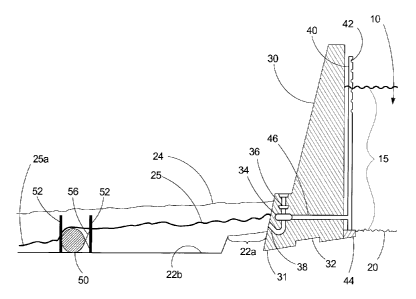
Fig. 1 illustrates an exemplary conventional hydroelectric power-generating
installation comprising a dam structure 30 configured for retaining
"impounded"
water 10 in an upstream reservoir bed 20 and discharging spent water into a
downstream waterway having a natural river bed 22 and opposing riverbanks 24.
The
downstream waterway typically comprises a tailrace pool 21a adjacent the dam
30
provided with at its distal end, a fixed-in-place impediment 21 b in the form
of a berm
comprising excavated fill materials 21 c, that has the purpose of retaining
spent water
released from the outlets of a tailrace 38 at a downstream surface level that
keeps
the outlets of the tailrace 38 submerged. The bases of conventional dam
designs
25 typically are provided with a mid-point keyway 32 and a toe region 31
underneath the
turbines for stability. The dam structure 30 is also typically provided with a
support
44 for a stand pipe 40 configured with intake apertures 42 for receiving water
from
the reservoir 10 and transferring said water to a penstock 46 wherein it is
conveyed to
a turbine 34 configured to drive an electricity-producing generator 36. Spent
water is
discharged from the turbine 34 out through the outlets of the tailrace 38
which
discharges the spent water from the dam 30 into the downstream waterway
defined by
REPLACEMENT SHEET
CA 02592359 2011-02-25
9
the riverbanks 24. The height of the water column 15 contained within the
stand pipe
40 between the uppermost of the intake apertures 42 and the turbine 34 is
commonly
referred to as the "head" of the impounded water 10. The height of the water
column
15 contained within the stand pipe 40 between the uppermost intake 42 and the
outlets
of the tailrace 38 is commonly referred to as the "effective net head" of the
impounded water 10. The weight of the water within the stand pipe 40 provides
the
pressure to drive the turbine 34. The portion of the water column interposed
the
uppermost water inlet 42 and the downstream surface level of the spent water
25 is
the "net head". Increasing the effective net head, i.e., the height of the
water column
15 from its surface level in the stand pipe 40 to the outlet of the tailrace
38 will
increase the water pressure delivered to the turbine 34 thereby increasing
power
generation by the generator 36. Increasing the net head in most conventional
installations can only be accomplished by increasing the height of the dam
structure
30 thereby raising the level of the impounded water 10. However, this approach
is
usually not practical or physically possible.
In order to avoid cavitation in the turbines during low-water flow conditions
caused by extended periods of dry conditions and/or drought that result in
declining
upstream and downstream water levels, conventional dam designs place the
outlets of
the tailrace 38 of the dam 30 as close as possible to the bottom of the
tailrace pool 2 la
in order to: (1) keep the turbines 36 flooded with water, and (2) provide
maximum net
head. The construction of the fixed-in-place impediment 21b with excavated
materials
21c to form the tailrace pool 21 a increases the surface level 25 of the spent
water
retained in the tailrace pool 21 a to keep the outlets of the tailrace 38
submerged.
The consequence during periods of high water flow rates caused by maximum
power production or during periods of excessive precipitation and/or snow
melt, is
that the downstream surface level of the spent water 25 may increase
considerably
above top of the fixed-in-place impediment 21b with the result that the that
net head
decreases to the distance between the uppermost water inlet 42 and the
downstream
water level 25, i.e., instead of the distance between the uppermost water
inlet 42 and
the turbine 34. In this situation, the decrease in the net head causes a
directly
proportional decrease in power production by the generator 36 driven by
turbine 34.
REPLACEMENT SHEET
CA 02592359 2007-06-20
The consequence during periods of low water flow rates through the turbine 34
as
a consequence of turbine idling during periods of low power production demand
or
alternatively, during extended periods of drought, is that the downstream
water level 25
retained in the tailrace pool 21 a may drop significantly thereby exposing the
outlet of the
5 tailrace and facilitating the occurrence of cavitation.
Exemplary embodiments of the present invention provide systems, apparatus and
methods for maximizing the effective net heads of hydroelectric dam
installations and for
controllably manipulating the downstream levels of discharged water adjacent
dam
installations in response to reduced volume discharges of spent water into the
tailrace
10 pool due to lower power production or during turbine idling, and/or to
environmental
changes in volumes of water delivered into reservoirs configured for storing
impounded
water. During periods of high power production and/or during periods of high
water flow
rates into impounded water reservoirs, the exemplary embodiments cooperate to
maintain
the "effective net head" of the head and to efficiently remove discharged
spent water
from the dam thereby maintaining the optimum height of the "effective net
head". During
periods of low water flow rates through turbines 34, the exemplary embodiments
cooperatingly manipulated to maintain a selected downstream water level
adjacent the
tailrace outlets of the dam to remove the potential for cavitation at the
turbines caused by
air backing into turbine chambers through the tailrace outlets and while yet
maintaining
the optimum height of the "effective net head".
Certain exemplary embodiments of the present invention provide combinations of
downstream excavations and adjustable weir devices suitably placed within the
excavations downstream from, but proximate, the tailrace pool areas of
hydroelectric dam
installations. As shown in Figs. 2 and3, a constructed berm (not shown)
defining the
distal end of a tailrace pool area 22a, may be removed from an existing
hydroelectric dam
installation and replaced with a suitable excavation 22b adjacent to the
tailrace pool area
22a. The excavation 22b extends downstream for a suitable distance before
conjoining
the natural river bottom. The purpose of the excavation 22b is to provide a
longer vertical
distance of spent water to fall from the tailrace 38 and the tailrace pool
area 22a,
therefore increasing the "effective net head". If so desired due to the
topography of the
DM_V AN/265880-00003/6696299.2
CA 02592359 2007-06-20
11
downstream riverbed, additional excavations, exemplified by excavation 22c in
Fig. 4,
maybe installed downstream adjacent to the first excavation 22b in order to
maintain and
extend positive egress of spent water 25 from the tailrace pool area 22a
further
downstream thereby providing a gravitational means for ensuring high rates of
water flow
through the turbines of a hydroelectric dam during seasonal periods when
impounded
water 10 levels significantly decline.
In conjunction with subsequent and/or deeper excavations provided adjacent the
tailrace pool area, exemplary embodiments of the present invention also
provide at least
one adjustable weir device and optionally, a plurality of adjustable weir
devices for
installation into the excavations as exemplified in Figs 5-14. The adjustable
weir devices
are configured for controllably engaging and communicating with the spent
water
discharged from the dam's tailrace(s). During periods of high rates of water
flow through
the dam installation, e.g., during spring run-off conditions and/or upstream
flood control
conditions, the adjustable weir devices are manipulably controllable to
provide minimal
resistance to spent water 25 flowing out of the tailraces 38 into the tailrace
pool areas 22a
so that the spent water 25 moves downstream from the dam as quickly as
possible. As the
rates of impounded water flow through the turbines decrease during seasonal
changes, the
adjustable weirs are manipulable to controllably provide resistance to the
flow of spent
water 25 out of the tailrace pool areas 22a, so that desired height levels of
spent water 25
are maintained adjacent the tailraces 38 of the dam as the rates of water flow
through the
penstocks 46, turbines 34 and out of the tailraces 38 decline, thereby
enabling means for
controlling and preventing cavitation in the turbines 34.
The adjustable devices according to the present invention may comprise
controllably inflatable and deflatable bladder devices. Figs. 5 to 7
illustrate an exemplary
embodiment comprising a plurality of inflatable bladders 50 conjoined by a
tether 54
fastened to the opposite river banks 24, and configured to span, or
alternatively partially
cross, or alternatively sit mid river in the downstream water from the dam 30.
Each
inflatable bladder 50 is attached by tethers 56 to a pair of supports 52 that
are securely
mounted into the excavation 22b installed into the river bottom adjacent the
tailrace pool
22a. During periods of high water flow rates into the impounded water
reservoir 10, the
DM VAN/265880-00003/6696299.2
CA 02592359 2007-06-20
12
bladders 50 are selectively and controllably deflated as shown in Fig. 5 to
enable
unrestricted flow of spent water 25 from the tailrace 38 into the tailrace
pool 21a
wherefrom it flows rapidly downstream. During extended dry periods as the
rates of
water flow continually decline, one or more bladders 50 are selectively and
controllably
inflated as shown in Figs. 6 and 7 to create an increasingly elevated
temporary
impoundment for discharged spent water 25 adjacent the tailrace pool area 22a
to
maintain the water level 25 at a desired level sufficiently high to prevent
air from backing
into the turbine through the tailrace 38 thereby preventing the onset of
cavitation.
However, those skilled in these arts will understand that during conditions
when
impounded water 10 levels decline as exemplified in Fig. 6, the reduced level
of spent
water 25a downstream of the bladders 50, relative to the level of spent water
25 upstream
to the bladders 50, will proportionally increase the "effective net head" and
thereby
facilitate increased power generation during such conditions.
Figs. 8 to 10 illustrate another exemplary embodiment of the inflatable
adjustable
weir devices of the present invention comprising a plurality of conjoined
bladder
infrastructures 60 installed within a retaining framework 62 securely mounted
into the
excavation 22b installed into the river bottom adjacent the tailrace pool 22a,
and
configured to span a area downstream from the tailrace pool 22a. Each bladder
infrastructure 60 is separately and independently inflatable and deflatable.
During periods
of high water flow rates into the impounded water reservoir 10, the bladder
infrastructures 60 are deflated as shown in Fig. 8 to enable unrestricted flow
of spent
water 25 from the tailrace 38 into the tailrace pool 21a wherefrom it flows
rapidly
downstream 22. During extended dry periods as the rates of water flow
continually
decline, one or more bladder infrastructures 60 are inflated as shown in Figs.
9 and 10 to
create an increasingly elevated temporary impoundment for discharged spent
water 25
adjacent the tailrace 38 to maintain the water level 25 sufficiently high in
the tailrace pool
area 22a to prevent air from backing into the turbine through the tailrace 38.
Those
skilled in these arts will understand that during conditions when impounded
water 10
levels decline as exemplified in Fig. 9, the reduced level of spent water 25a
downstream
of the bladder infrastructures 60, relative to the level of spent water 25
upstream to the
DM VAN/265880-00003/6696299.2
CA 02592359 2007-06-20
13
bladder infrastructures 60, will proportionally increase the "effective net
head" and
thereby facilitate increased power generation during such conditions.
Those skilled in these arts will understand that the exemplary bladders 50 and
bladder infrastructures 60 can be controllably inflated and deflated by
cooperation and
communication with a compressed air supply. Those skilled in these arts will
also
understand that the compressed air equipment (not shown) can be installed in
suitable
housing structures on the shores of the waterway approximate the adjustable
weir
devices. Alternatively, the compressed air may be supplied from a dam
utilities support
facility by a piping infrastructure. It is suitable that the compressed air
supply to the
adjustable weir device is configured and installed above the predetermined
downstream
"high-water" levels for ease-of-access for repair and service work.
Alternatively, the adjustable weir apparatus may comprise a constructed-in-
place
infrastructure provided with and cooperating with at least one upwardly
extendable
and/or swinging gate structure. Figs. 11 through 14 illustrate an exemplary
embodiment
based on a coffre-type dam configuration provided with a reinforced concrete
wall and
framework 70 extending across the downstream waterway and conjoining the river
banks
24. The concrete wall and framework 70 are buttressed and stabilized by a
plurality of
spaced-apart integrally conjoined braces 74. A plurality of controllably
adjustable gates
72 are hingedly and/or extendibly engaged with the concrete wall and framework
70. A
controlling device (not shown) is communicably interconnected with the each of
the gates
72 to sealingly engage and disengage the gates 72 with the concrete walls and
framework. During periods of high water flow rates into the impounded water
reservoir
10, the gates 72 are adjusted into a fully open position as shown in Fig. 11
and 12, to
enable unrestricted flow of spent water 25 from the tailrace 38 through the
tailrace pool
22a wherefrom it flows rapidly downstream. As the rates of water flow
progressively
decline during turbine idling or during extended periods of drought
conditions, one or
more of the gates 72 are partially closed as shown in Fig. 13 to create an
increasing
restriction on the flow of discharged spent water 25 thereby maintaining the
water level
sufficiently high to prevent air from backing into the turbine through the
tailrace 38. Fig.
14 shows the gates 72 in a sealingly closed engagement with the concrete wall
and
DM_V AN/265880-00003/6696299.2
CA 02592359 2007-06-20
14
framework 70 thereby causing the spent water 25 to flow over top of the
framework 70
and gates 72 in order to maintain the spent water level 25 at the desired
level within the
tailrace pool area 22a during extended periods of drought or during turbine
idling
conditions. Those skilled in these arts will understand that during conditions
when
impounded water 10 levels decline as exemplified in Figs. 13 and 14 or the
turbines are
in idling mode, the reduced levels of spent water 25a downstream of the
bladder
infrastructures 60, relative to the level of spent water 25 upstream to the
bladder
infrastructures 60, will proportionally increase the "effective net head" and
thereby
facilitate increased power generation during such conditions.
The exemplary embodiments of the present invention comprising controllably
adjustable weirs are also amenable for installation in an unexcavated riverbed
downstream of a tailrace pool 21 a provided with an installed berm 21 c
comprising
excavated materials, as shown in Figs 15 and 16. Fig. 15 shows a coffre-type
adjustable
weir device 90 connected to one shore and partially crossing the river.
Alternatively, the
adjustable weir device 90 can be positioned separated and free-standing from
the river
shores, for example as shown in Fig. 16, mid-stream in the path of the
discharged spent
water. The configurations and designs of the adjustable weirs of the present
invention are
configurable and manipulable to enable the use of the present invention with a
variety of
structural designs for hydroelectric installations and/or with a variety of
environmental,
geophysical and topographical sites, so that the attendant minimum and maximum
discharge volumes of spent water can be controllable adjustable and
manipulable suitable
control devices interconnected to and cooperable with the adjustable weirs of
the present
invention. It is suitable that the control devices and mechanisms for the weir
are located
in controls housing structures on the shore(s) of the waterway, or
alternatively, on the
dam infrastructure. It is also suitable that routing of the mechanisms for
controllably
engaging and disengaging the gates of coffer-type adjustable weir devices of
the present
invention are positioned above the highest levels reached by the spent water
25 and are
accessible by service staff above the water levels.
Another exemplary embodiment of the present invention provides a series of
controllably adjustable weirs placed sequentially downstream from a
hydroelectric dam
DM VAN/265880-00003/6696299.2
CA 02592359 2007-06-20
installation as shown in Figs. 17-19 and are exemplified by the inflatable
bladders 50,
tethers 54, 56, and supports 52 from Figs. 5-7. During seasonal periods when
impounded
water levels 10 are very high, the bladders 50 would be completely deflated as
shown in
Fig 17 so as to present as small impediments as possible to the rapid egress
of spent water
5 25 from the tailraces 38. As the level of impounded water 10 begins to
decline as shown
in Fig. 18, the bladders 50 may be selectively inflated to affect the
retention and the rate
of flow of spent water 25 from the tailrace pool area 22a. During seasonal
periods when
the level of upstream impounded water 10 is relatively low as shown in Fig.
19, it is
suitable to fully inflate the bladders 50 in the first adjustable weir
downstream from the
10 dam, while the further downstream adjustable weirs are completely deflated.
This
combination will enable maintenance of a target level of spent water in the
tailrace pool
area 22a selected to prevent cavitation in the turbines 34, while providing a
significant
drop between the spent water level in the tailrace pool area 22a and the
downstream area
from the first adjustable weir to enable rapid egress of spent water 25a from
the tailrace
15 pool area upstream of the first adjustable weir. While Figs. 17-19 show a
series of three
sequential sets of adjustable weirs, those skilled in these arts will
understand that the
numbers and placement of sequential sets of adjustable weirs are selectable
depending on
the requirements and restrictions imposed by the topography of the downstream
waterway and its banks.
Another exemplary embodiment of the present invention provides a downstream
placement of impediments that may potentially interfere with the rapid egress
of spent
water from hydroelectric dam installations. The impediments may be naturally
occurring
topographical elevations, boulder formations, large rocks and the like. It is
to be noted,
however, that those skilled in these arts will understand that this embodiment
as
described above is intended for retrofitting existing hydroelectric dam
installations with
for the purpose of intentionally providing downstream impediments to the flow
of spent
water downstream from the adjustable weir and excavation embodiments of the
present
invention.
While this invention has been described with respect to the combination and
cooperation of the exemplary first and second embodiments, those skilled in
this art will
DM VAN/265880-00003/6696299.2
CA 02592359 2007-06-20
16
understand how to modify and adapt the systems, apparatus and methods
disclosed herein
for increasing the head height of hydroelectric dams and for controllably
manipulating
the level of discharged spent water adjacent dam tailraces. Furthermore, those
skilled in
these arts will understand that the first and second exemplary embodiments can
be
individually retrofitted, i.e., installed downstream to an existing
hydroelectric generating
dam for: (a) in the case of the first exemplary embodiment to increase the
head height in
order to increase the power-generating capacity of the dam, or (b) in the case
of the
second exemplary embodiment to enable controllable manipulation of the
discharged
spent water to maintain a selected minimum downstream water level adjacent the
tailrace(s). It is also within the scope of the present invention to provide
secondary
excavations within primary excavations, wherein the primary excavations are
provided
for increasing the rates of spent water egress from tailrace pool areas while
the secondary
excavations are configured to contain therein the adjustable weir devices
disclosed
herein. The secondary excavations would enable the retraction of the
adjustable weir
devices to the level of the primary excavation so that they do not provide
impediments
and thus resistance to the egress of spent water during periods of high
impounded water
levels and throughput rates.
It is also within the scope of the present invention to provide: (a)
excavations
adjacent the tailrace pool areas of the hydroelectric dam installations, that
are of
sufficient depth to cause cavitation in turbines when rates of impounded water
flow
through the penstocks and turbines are seasonally or intentionally reduced,
and (b)
controllably adjustable weirs according to the exemplary embodiments disclosed
herein,
for manipulably maintaining spent water levels at desired levels adjacent the
tailraces to
prevent the occurrence of cavitation. Those skilled in these arts will
understand the
controllable imposition of stress on a hydroelectric dam installation by
providing an
excavation adjacent the tailrace pool area, while ameliorating the stress by
controllably
preventing turbine cavitation will result in increased power generation under
such
conditions.
Therefore, it is to be understood that various alterations and modifications
can be
made to the excavations, adjustable weir devices, apparatus and associated
methods
DM VAN/265880-00003/6696299.2
CA 02592359 2007-06-20
17
within the scope of this invention and are intended to be included herein. In
view of
numerous changes and variations that will be apparent to persons skilled in
the art, the
scope of the present invention is to be considered limited solely by the
appended claims.
DM VAN/265880-00003/6696299.2