Note: Descriptions are shown in the official language in which they were submitted.
CA 02592404 2010-05-04
CONSTANTCONTACT SIDE BEARING
BACKGROUND OF INVENTION
Field of Invention
The present invention related to an improved side bearing design for mounting
on
a railroad car truck bolster that allows long travel, substantial weight
reduction, improved
hunting and curving characteristics, and various ease of installation
features.
Description of Related Art
In a typical railway freight train, such as that shown in Fig 1 at 10, railway
cars 12, 14
are connected end to end by couplers 16, 18. Couplers 16, 18 are each received
in draft
sills 20, 22 of each respective car along with hydraulic cushioning or draft
gear
assemblies (unshown). Draft sills 20, 22 are provided at the ends of the
railway car's
center sill, and include center plates that rest in center plate bowls of
railway car trucks
26, 28.
As better shown in Fig. 2, each typical car truck 26 includes a pair of side
frames
30, 32 supported on wheel sets 34, 36. Bolster 38 extends between and is
supported on
springs 40 mounted on side frames. A bolster center plate 24 is provided
having a central
opening 42. The bolster center plate bowl 24 received and supports a circular
center plate
of the draft sill 20. Side bearing pads 60 are provided laterally to each side
of center
plate 24 on bolster 38. Side frames 30, 32 comprise a top member 44,
compression
member 46, tension member 48, column 50, gib 52, pedestal 54, pedestal roof
56,
bearings 58 and bearing adapter 62.
Constant contact side bearings are commonly used on railroad car trucks. They
are typically located on the truck bolster, such as on side bearing pads 60,
but may be
1
CA 02592404 2007-06-20
located elsewhere. Some prior designs have used a single helical spring
mounted between
25 a base and a cap. Others use multiple helical springs or elastomer
elements. Exemplary
known side bearing arrangements include U.S. Patent No. 3,748,001 to Neumann
et al
and U.S. Patent No. 4,130,066 to Mulcahy.
Typical side bearing arrangements are designed to control hunting of the
railroad
car. That is, as the semi-conical wheels of the railcar truck ride along a
railroad track, a
30 yaw axis motion is induced in the railroad car truck. As the truck yaws,
part of the side
bearing is made to slide across the underside the wear plate bolted to the
railroad car
body bolster. The resulting friction produces an opposing torque that acts to
prevent this
yaw motion. Another purpose of railroad car truck side bearings is to control
or limit the
roll motion of the car body. Most prior side bearing designs limited travel of
the bearings
35 to about 5/16". The maximum travel of side bearings is specified by the
Association of
American Railroads (AAR) standards. Previous standards, such as M-948-77,
limited
travel to 5/16" for many applications.
New standards have evolved requiring side bearings that have improved hunting,
curving and other properties to further increase the safety and design of
railcars. The
40 most recent AAR standard is M-976 that now allows for longer travel side
bearings and
has several new requirements, such as new specifications for bearing preloads.
Preload is
defined as the force applied by the spring element when the Constant Contact
Side
Bearing is set at the prescribed height.
2
CA 02592404 2007-06-20
SUMMARY OF THE INVENTION
45 There is a need for improved side bearings for railroad cars that can meet
or exceed these new AAR standards, such as M-976 or Rule 88 of the AAR Office
Manual.
There also is a need for side bearings with better wear characteristics to
increase
service life, as a wear test has been added to AAR Standard M-948.
50 There further is a need for side bearings that can be designed for a
particular
application by incorporating design features that prevent interchangeability
of incorrect
components for that application.
There also is a need for a side bearing which maintains the preload force
within
10% of the new condition for a long time. Preferably, this condition should be
a
55 minimum of 10 years or one million miles.
There also is a need for redesigned spring rates to improve handling
characteristics of the truck and railroad car.
There also is a need for a standardized set of springs that can reduce parts
inventories of various custom spring sizes.
60 The above and other advantages are achieved by various embodiments of the
invention.
In exemplary embodiments, long travel can be achieved in a side bearing
arrangement for railroad car trucks by a combination of features, including
reduction of
base and/or cap heights and/or reduction of the spring solid height to
accommodate 5/8"
65 travel or more before the spring is fully compressed (solid) and before the
base and cap
bottom out.
3
CA 02592404 2007-06-20
In exemplary embodiments, substantial weight reduction is achieved by reducing
sides and thicknesses of the base and cap in areas not needed for structural
rigidity.
In exemplary embodiments, improved inspection capabilities are achieved by
70 addition of an inspection slot to the base and increasing a corresponding
side cutout in the
cap to provide a viewing window of considerable size that allows inspection of
the spring
and other internal components of the side bearing during use. This feature
also is able to
achieve weight saving advantages over prior designs.
In exemplary embodiments, various design features are incorporated to the base
75 and/or cap to prevent interchangeability with improper components. This may
include
features that allow mating of only matching base and cap components. Such
mating may
further include features that prevent improper orientation of the base
relative to the cap.
Such interchangeability prevention features may further include features that
prevent use
of improper spring(s) with universal base and cap. Also, the springs can be
wound in the
80 opposite direction of the adjacent spring to preclude one spring
interfering with the travel
of this adjacent spring.
In exemplary embodiments, improved, longer fatigue life is achieved by
increasing the hardness of the components from Grade C to Grade E, or by using
cast
iron components.
85 In exemplary embodiments, improved operation of the side bearing, including
improved control and hunting characteristics, is achieved by careful control
of
longitudinal clearances between the cap and base. This has been found to be
important to
prevent excessive movement between the cap and base, as well as reduce
associated
impact forces, stresses and wear.
4
CA 02592404 2007-06-20
90 In exemplary embodiments, improved characteristics of the side bearing and
service life are achieved by strategic placement of hardened wear surfaces.
In exemplary embodiments, improved tracking, curving and load leveling
characteristics
are achieved without adversely affecting hunting characteristics by changing
the spring
constant to be within a predetermined range, preferably between 2500-4000
lb/in.
95 In exemplary embodiments, a standardized set of three different springs are
provided that can be mixed and matched in various combinations to achieve
different
preload values for use in a multitude of applications, while reducing the need
for special,
custom-designed springs for each application.
In exemplary embodiments, a better contact surface arrangement with a car body
100 wear plate is achieved by coping the cap corners and increasing the
flatness of the cap top
contact surface to improve wear characteristics, such as reduced gouging.
BRIEF DESCRIPTION OF THE DRAWINGS
The invention will be described with reference to the following drawings,
wherein:
105 Figure 1 is a schematic elevation of the coupled ends of two typical
railroad cars;
Figure 2 is a perspective view of a typical railway car truck for use with the
present invention;
Figure 3 is an exploded perspective view of an exemplary constant contact side
bearing according to the invention;
110 Figure 4 is a cross-sectional view of an exemplary constant contact side
bearing
according to the invention;
CA 02592404 2007-06-20
Figure 4A is a partial detailed view of the coil springs and spring base of an
embodiment of the present invention;
Figure 4B is a cross-sectional view of an exemplary constant contact side
bearing
115 according to the present invention;
Figure 5 is a perspective view of a spring base in accordance with an
embodiment
of the present invention;
Figure 6 is a perspective view of a first exemplary constant contact side
bearing
base according to the invention;
120 Figure 7 is a cross-sectional view of the first exemplary side bearing
base;
Figure 8 is a top view of the first exemplary side bearing base;
Figure 9 is a perspective view of the exemplary side bearing cap according to
the
invention;
Figure 10 is a cross-sectional view of the exemplary side bearing cap
according to
125 the invention, and
Figure 11 is a top view of the exemplary side bearing cap.
DETAILED DESCRIPTION OF THE PREFERRED EMBODIMENTS
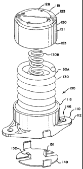
A first embodiment of a side bearing according to the invention will be
described with reference to Figs 3-11. Side bearing assembly 100 has a major
130 longitudinal axis coincident with the longitudinal axis of a railway car.
That is, when the
side bearing is mounted on railway truck bolster 38, the major axis of the
side bearing is
perpendicular to the longitudinal axis of the bolster. Side bearing assembly
100 includes
as main components, a base 110, a cap 120, and one or more resilient urging
elements
130, such as a spring or elastomer element, and spring base 131. In the
exemplary
6
CA 02592404 2007-06-20
135 embodiment shown, there are provided two springs, outer spring 130A, and
inner spring
130B that serve as the urging element, each of which may have a different
spring
constant to provide an overall combined load rating.
Base 110 is fixed to bolster 38 by suitable means. As shown, base 110 is
bolted to
bolster 38 by way of mounting bolts (not shown) passing through mounting holes
146
140 provided on base flanges 112.
As best shown in Figs. 3 & 4, and 6-8, base 110 has generally open cylindrical
wall 116 that extends upwardly from base 110. Wall 116 may, in certain
embodiments,
include two openings 114. Opening 114 serves as an opening for the head of a
wrench
used to tighten the bolts passing through bolt holes 146. Opening 114 also
serves to
145 reduce weight of the base 110.
To increase the travel length of the side bearing, walls 116 are reduced in
total
height by 5/16" from prior designs, such as that used in U.S. Patent No.
3,748,001. This
helps to achieve greater travel of the spring before cap 120 and base 110 mate
and
prevent further travel. In an exemplary embodiment, base 110 has a total
height of 4.188
150 in. (+/- 0.030), with walls 116 extending approximately 3.626 in. above
flange 112.
Referring to Figs. 3&4 and 9-11, cap 120 is cup-shaped and includes generally
circular top section 119 downwardly extending general cylindrical side walls
121, that
enter base 110 open wall 116 in a telescoping fashion. As shown in Fig 4B, cap
side
walls 121 can include a protruding ridge on another 124 surface that can be U
or V
155 shaped corresponding in location with opening 114 on an inner surface of
base wall 116
to restrict or prohibit the rotation of cap 120 in base 110. The downwardly
extending wall
121 of cap 120 extend into wall 116 of base 110 in such a fashion that even
when the
7
CA 02592404 2010-05-04
spring(s) 130 are at their free height or in an uncompressed condition, there
is still
provided an amount of overlap between wall 121 and wall 116.
160 Cap 120 is further provided with a top contact surface 128, lower stop
edge 123,
and lower recessed spring support surface 127. Preferably, all peripheral
edges 129 are
Coped or rounded with a scoped or flat transition area 119 extending from top
contact
surface 128 to edge 123. This serves several purposes. It reduces weight of
the cap.
Moreover, by coping the corners, there is a better contact surface is made
that abuts
165 against a car body wear plate (unshown but located on the underside of a
car body
immediately above cap 120 in use). In particular, by having coped corners, it
has been
found that less gouging occurs on the car body wear plate when the cap slides
and rotates
in frictional engagement with the car body wear plate during use. To further
assist in a
better contact surface, top contact surface 128 is formed substantially flat,
preferably
170 within 0.010" concave or 0.030" convex to further improve wear
characteristics. In
particular, this bias reduces the chance of the edge "binding" against the
wear plate and is
easier to manufacture.
To assist in providing long travel of the springs, cap 120 is shortened
similar to
that of base 110. In an exemplary embodiment, cap 120 is shortened in height
by 5/16"
175 over previous designs to allow further travel of spring(s) 130 before cap
120 and base
1 10 mate and prevent further travel. Cap 120 preferably has a total cap
height of 3.875
in., with side wall 121 extending downward approximately 3.375 in. below lower
support
surface 127. This allows the cap to insert farther onto base 110 before lower
stop edge
contacts the inside surface of base 110.
8
CA 02592404 2007-06-20
180 As mentioned, the inventive side bearing cap 120 and base 110 can be
used with one or more urging members, such as springs 130. To achieve long
travel of at
least 5/8", it is preferably to reduce the spring solid height from that used
in prior designs.
This is because prior spring designs would have gone solid before 5/8" of
travel was
achieved. That is, the individual spring coils would have compressed against
each other
185 so that no further compression was possible.
Although two springs per side bearing are described in the embodiments, the
invention is not limited to this and fewer, or even more, springs could be
used. In fact, the
number and size of springs may be tailored for a particular application. For
example,
lighter cars will use a softer spring rate and may use softer springs or fewer
springs.
190 Similarly, multi-unit articulated cars may use lighter or fewer springs
because such cars
use four side bearings instead of two per truck. As such, the load carrying
capacity of
each must be reduced. Also, it has been found that better performance can be
achieved
through use of substantially stiffer spring constants than previously used.
This has been
found to provide a suspension system with a slower reaction time, which has
been found
195 to achieve improved tracking and curving, without adversely affecting
hunting. This also
has been found to result in reduced sensitivity to set-up height variations or
component
tolerances so as to achieve a more consistent preload on the truck system.
This tends to
equalize the loading and allow a railcar to stay more level, with less lean or
roll both
statically and dynamically.
200 To obtain longer fatigue life, the material used for base 110 and cap 120
can be
Grade E steel or cast iron. To assist in longer service life, hardened wear
surfaces are
provided on the outside surfaces of base wall 116.
9
CA 02592404 2007-06-20
Additionally, in an exemplary preferred embodiment, to prevent excessive
movements and accelerated wear, reduced longitudinal clearances between cap
120 and
205 base 110 are provided by reducing the tolerances from prior values. This
can be achieved,
for example, by more closely controlling the casting or other formation
process of the cap
120 and base 110 side walls. In a preferred embodiment, base 100 has a
longitudinal
distance of 7.000" (+0.005/-0.015) between inside surfaces of side wall 116
and outside
surfaces of side wall 121 of cap 120 have a longitudinal distance of 7.031"
(+0.000/-
210 0.020). This results in a closely controlled combined longitudinal spatial
gap having a
minimum of 0.006" and maximum of 0.046". The minimum is achieved when base
side
wall 116 is at the maximum tolerance of 7.005" and cap side walls 121 are at
the
minimum tolerance of 7.011." The maximum is achieved when the base side wall
116 are
at the minimum tolerance of 6.985" and the cap side walls 121 are at the
maximum
215 tolerance of 7.031."
Because of the possibility of various spring combinations, it is desirable to
provide a safety feature that prevents interchangeability of improper
components for a
given application. To achieve this, exemplary embodiments provide keying
features on
both the cap 120 and base 110 to prevent mismatch of components. Also, cap 120
can be
220 provided with spring lockout features that prevent improper combinations
of springs to be
used.
Further, base 110 is seen to have a generally cylindrical opening 147 that is
centrally located between flange 112. As shown in Fig. 5, a spring base 149 is
located in
cylindrical opening 147. Spring base 149 is generally circular, with two
identical spring
225 supports 151, 152 extending upwardly from a near center location. Spring
supports 151,
CA 02592404 2007-06-20
152 are raised formed siding the inner support spring 130A. Spring base 149 is
usually a
fabricated steel component. The support will not allow an improper spring to
be inserted
into the assembly, which would provide too much preload for the weight of the
car body.
11