Note: Descriptions are shown in the official language in which they were submitted.
CA 02592549 2007-06-20
PATENT
1
PLASTIC PEGBOARD ASSEMBLY
DESCRIPTION
TECHNICAL FIELD
[0001] The invention relates to a plastic pegboard assembly comprising a
plurality of
pegboard members that are coupled by a connector and secured in a spaced
relation from a
wall.
BACKGROUND OF THE INVENTION
[0002] Display wall panels such as pegboards are commonly known in the art.
Pegboard
panels are frequently used to display or store items, tools, supplies or
accessories along a wall
without contacting the finished wall behind the pegboard. Pegboards are most
commonly
found in garages, work sheds or utility rooms, in which there may be less room
for bulky
storage containers. Wall storage is, therefore, a practical solution.
Typically, pegboards are
available in large sheets, having a pre-determined size and configuration, and
must be
mounted using additional mounting hardware that appropriately space the
pegboard a certain
distance from the wall. The pegboards are commonly made of wood including wood
particle
board. The large pegboard sheets can be cumbersome to handle and difficult to
mount.
Furthermore, the final mounting of a plurality of adjacent pegboards is often
times not
aesthetically pleasing to users.
[0003] While such pegboards, according to the prior art, provide a number of
advantageous features, they nevertheless have certain limitations. The present
invention is
provided to overcome certain of these limitations and other drawbacks of the
prior art, and to
provide new features not heretofore available. A full discussion of the
features and
21653127.2
CA 02592549 2007-06-20
2
advantages of the present invention is deferred to the following detailed
description, which
proceeds with reference to the accompanying drawings.
SUMMARY OF THE INVENTION
[0004] The present invention provides for a pegboard assembly configured to
couple a
plurality of pegboard members and be secured in a spaced relation against a
wall. In one
preferred embodiment, a pegboard assembly is provided having a plurality of
pegboard
members, in which the first pegboard member is coupled to the second pegboard
member by
a connector. In one preferred embodiment, the pegboard members are plastic.
[0005] According to a first aspect of the invention, a pegboard assembly is
provided
having a plurality of pegboard members. The pegboard member has a front side
and a rear
side, and has a plurality of holes defined therethrough. The rear side has a
plurality of
reinforcement ribs having an integral spacer element. The spacer element
extends from the
reinforcing rib, and is adapted to contact the wall such that the holes are
adapted to be spaced
from the wall.
[0006] According to another aspect of the invention, a pegboard assembly is
provided
having a plurality of pegboard members. The plurality of pegboard members are
operably
connected by a connector. The pegboard members and connector have a
cooperative
structure to connect the pegboard members. In one preferred embodiment, the
pegboard
members have a generally T-shaped tongue that is received by a generally T-
shaped groove
in the connector.
[0007] Other features and advantages of the invention will be apparent from
the
following specification taken in conjunction with the following drawings.
BRIEF DESCRIPTION OF THE DRAWINGS
[0008] To understand the present invention, it will now be described by way of
example,
with reference to the accompanying drawings in which:
FIG. 1 is a perspective view of a pegboard assembly according to the present
invention;
FIG. 2 is a perspective view of the pegboard assembly according to the present
invention, showing pegboard members being connected by a connector and showing
additional connection configurations;
21653127.2
CA 02592549 2007-06-20
3
FIG. 3 is a partial perspective view of an edge of a pegboard member according
to the
present invention;
FIG. 4 is a partial perspective view of a pegboard member and a connector
according
to the present invention;
FIG. 5 is a partial perspective view of a first pegboard member, a second
pegboard
member, and a connector according to the present invention;
FIG. 6 is a cross-sectional view of FIG. 1 taken along lines 6-6 of the
pegboard
assembly of FIG 1;
FIG. 7 is a partial rear view of the pegboard member of the present invention;
FIG. 8 is a cross-sectional view taken along lines 8-8 of the pegboard member
of
FIG. 1; and
FIG. 9 is a partial schematic cross-sectional view of the pegboard assembly
mounted
to a wall and showing a hook mounted on the pegboard assembly.
DETAILED DESCRIPTION
[00091 While this invention is susceptible of embodiments in many different
forms, there
is shown in the drawings and will herein be described in detail preferred
embodiments of the
invention with the understanding that the present disclosure is to be
considered as an
exemplification of the principles of the invention and is not intended to
limit the broad aspect
of the invention to the embodiments illustrated.
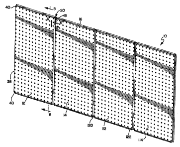
[0010) Referring to the drawings, FIG. 1 discloses a plastic pegboard assembly
according
to the present invention, generally designated by the reference numeral 10. As
shown in
FIGS. 1 and 2, the pegboard assembly 10 generally has a first pegboard member
12, a second
pegboard member 14, and a connector 18. FIGS. 2 and 5 show a first pegboard
member 12
and a second pegboard member 14 coupled with the connector 18 that will be
discussed in
greater detail below. The pegboard members 12,14 are generally identical. The
pegboard
assembly 10 is designed to be mounted on the wall in any number of desired
configurations
as shown in FIG. 2 such as in a horizontal position or in a vertical position.
The number of
pegboard members that are used will vary depending on the desired size of the
entire
pegboard assembly 10. Accordingly, as shown in FIG. 1, additional connectors
18 can be
utilized to connect a third pegboard member 112 to the second pegboard member
14 and a
fourth pegboard member 114 can be connected to the third pegboard member 112.
Other
21653127.2
CA 02592549 2007-06-20
4
combinations of pegboard members 12 can also be utilized and this will be
described in
greater detail below.
[0011] As shown in FIG. 1, a cooperative structure 20 is utilized between the
pegboard
members 12,14 and the connector 18. The cooperative structure 20 allows for
the pegboard
members 12,14 to fit securely into the connector 18 resulting in the pegboard
assembly 10.
The cooperative structure 20 generally comprises a structural feature between
the pegboard
member 12 and the connector 18 to allow for additional connections between
pegboard
members 12. The connector 18 operates as a part of the cooperative structure
20 between the
first pegboard 12 and the second pegboard 14 for coupling the first pegboard
12 to the second
pegboard 14. As discussed in greater detail below, a tongue and groove
arrangement is one
preferred embodiment of the cooperative structure 20 although other structures
could be
utilized.
[0012] The particular pegboard members 12 shown in FIG. 1 are made of plastic
although
they could also be made from other materials including wood. Thus, in one
preferred
embodiment, the pegboard members 12 can be made from a plastic injection-
molded process
as is understood in the art. The structure of the first pegboard member 12
will be described
with the understanding that the structure of other pegboard members 14,112,114
are generally
identical. FIG. 1 shows the pegboard member 12 having a plurality of holes 16
defined
therethrough. The plurality of holes 16 may be arranged at regular intervals
or intermittently
throughout the pegboard members 12. As shown in FIGS. 7 and 8, the pegboard
member 12
has a front side 58 and a rear side 48 that are generally planar. The front
side 58 has a
generally smooth surface. The rear side 48 also has a generally smooth surface
but has a
plurality of reinforcing ribs 52 extending from the rear side 48. The
reinforcing ribs 52 will
be discussed in greater detail below. In one preferred embodiment, the
pegboard member 12
is generally rectangular although other shapes are readily possible.
[0013] As shown in FIGS. 1-3, the pegboard member 12 has a first peripheral
edge 38
and a second peripheral edge 40. The second peripheral edge 40 is generally
transverse to the
first peripheral edge 38. The first peripheral edge 38 is generally vertically-
oriented in FIG. 3
and the second peripheral edge 40 is generally horizontally-oriented in FIG.
3. It is
understood that the pegboard member 12 may generally have a pair of vertically-
oriented
peripheral edges 38 and a pair of horizontally-oriented peripheral edges 40.
The peripheral
edge 38 has a first tongue 42 extending therefrom. The second peripheral edge
40 also has a
21653127.2
CA 02592549 2007-06-20
second tongue 44 extending therefrom. The second tongue 44 extends generally
transverse to
the first tongue 42. In a preferred embodiment as shown in FIG. 3, the tongues
42,44 join at
a corner of the pegboard member 12. At this corner and shown in FIGS. 3 and 4,
a flared
ridge 43 is formed at generally an interface between the first tongue 42 and
the second tongue
44. The flared ridge 43 acts as a stop structure in cooperation with the
connector 18 as
described in greater detail below. The As can be understood from FIGS. 3-6,
the tongues
42,44 extend substantially perpendicular from the peripheral edges 38,40 and
are integral
with the pegboard member 12. In one preferred embodiment, the tongues 42,44
have a T-
shape, formed by a first member intersecting a cross-member. While the present
invention
has a tongue in the shape of a T, it is contemplated that the tongue 42,44 can
be of various
shapes and configurations providing for cooperation with the connector 18 as
further
described below. Thus, in a preferred embodiment, the first plastic pegboard
member 12 has
generally T-shaped tongues 42,44 extending from the peripheral edges 38,40 and
around the
full periphery of the pegboard member 12. The tongues 42,44 cooperate with the
connector 18.
(0014] As shown in FIG. 7, the rear side 48 of the first pegboard member 12
has a
reinforcing rib 52 that operates to add further support to the pegboard member
12 by
strengthening and stiffening the pegboard member 12. The pegboard member 12
may also
have a depending flange 60 extending around a periphery of the pegboard member
12 that
also may add rigidity and stiffness to the pegboard member 12. As further
shown in FIG. 7,
the reinforcing rib 52 has a first reinforcing member 64 and a second
reinforcing member 66.
The first reinforcing member 64 intersects the second reinforcing member 66 at
an
intersection area 54. It is understood that the reinforcing rib 52 has a
plurality of intersecting
first reinforcing members 64 and second reinforcing members 66 that make up a
grid like
structure on the rear side 48 of the pegboard member 12. As further shown in
FIG. 7, a
spacer element 50 extends from the intersection area 54. Each of the
intersecting areas 54
has a spacer element 50 extending therefrom as can be understood from FIG. 7.
The spacer
element 50 extends from the reinforcing rib 52, and is integral with the
reinforcing rib 52. In
a preferred embodiment, the spacer element 50 has a first spacer member 68 and
a second
spacer member 70. The first spacer member 68 intersects the second spacer
member 70 thus
forming a cross shape. As further shown in FIG. 7, the first spacer member 68
extends from
the first reinforcing member 64, and the second spacer member 70 extends from
the second
21653127.2
CA 02592549 2007-06-20
6
reinforcing member 66, generally at the intersection area 54. The spacer
members 68,70 of
the spacer element 52 define engaging surfaces to abut a wall and further
having a generally
curved segment 71 that meets the reinforcing members 64,66. In a preferred
embodiment,
the spacer element 50 and the reinforcing rib 52 are integral with the rear
side 48 of the
pegboard member 12 and formed in an injection molding process with the overall
pegboard
member 12.
100151 The spacer element 50 operates to contact the wall W upon mounting the
pegboard assembly 10, such that the holes 16 are spaced from the wall W as
shown in FIG. 9.
The spacer element 50 thus ensures that the plurality of holes 16 are spaced a
distance from
the mounting wall when installed in order to accommodate hooks or other
mounting
accessories through the holes 16. Thus, as shown in FIG. 9, the spacer element
50 is
designed to provide a space S between the rear side 48 of the pegboard 12 and
the mounting
wall W to allow any standard pegboard hooks or other accessories to fit into
the plurality of
holes 16 of the pegboard member 12.
[0016] FIGS. 1, 2 and 4-6 show the connector 18. The connector 18 generally
defines a
first groove and a second groove that in a preferred embodiment, are generally
T-shaped
grooves. As shown in FIG. 6, the connector 18 has a base 32, a first pair of
opposing walls
34 extending from the base 32 in one direction, and a pair of shoulders 36
extending inwardly
from the pair of the opposing walls 34. The connector 18 also has a second
pair of opposing
walls 34 extending in an opposite direction from the base 32. A second pair of
shoulders 36
extend inwardly from the second pair of opposing walls 34. The base 32, the
pairs of
opposing walls 34, and the pairs of shoulders 36 cooperatively define the
first groove 24 and
the second groove 28 of the connector 18. In a preferred embodiment, the first
groove 24 and
the second groove 28 are generally T-shaped grooves. As shown in FIGS. 4-6, it
is
understood that the connector 18 thus defines the first T-shaped groove 24
opposite the
second T-shaped groove 28. As explained in greater detail below, the T-shaped
grooves
24,28 receive the T-shaped tongues 42,44 of the pegboard member 12. Also, in
one preferred
embodiment, the grooves 24,28 extend the length of the connector 18 and are
open at each
end. In an alternative embodiment, one end of the connector 18 can be closed,
thus closing
off the grooves 24,28 at one end. This structure would help support the
pegboard members
12,14 as further discussed below.
21653127.2
CA 02592549 2007-06-20
7
[0017] One aspect of the present invention allows a user to create the
pegboard assembly
according to a desired size or configuration. Thus, by utilizing the
cooperative structure
between the pegboard member 12 and the connector 18, a user can assemble the
pegboard
assembly 10 in a number of different configurations.
[00181 For example, FIG. 1 shows a pegboard assembly 10 having four pegboard
members interconnected by three connectors 18. It is understood that the
pegboard members
12 may be suitably mounted to a mounting surface such as a wall using a
variety of known
mounting hardware. For example, traditional screws, drywall anchors or other
hardware can
be used. The holes 16 in the pegboard members 12,14 can be used in mounting
the pegboard
members 12,14. As shown in FIG. 9, the spacer elements 50 assure that a space
S is
maintained between the rear side 48 of the pegboard 12 and the wall W. The
second
pegboard 14 is connected to the first pegboard member 12. As can be understood
from FIGS.
1 and 4-6, the first tongue 42 of the first pegboard member 12 is received in
the first groove
24 of the connector 18 wherein the connector 18 is operably connected to the
first pegboard
member 12. As shown in FIGS. 1 and 5, the first tongue 42 of the second
pegboard member
14 is then received in the second groove 28 of the first connector 18 wherein
the second
pegboard member 14 is operably connected or coupled to the first pegboard
member 12. As
shown in FIG. 6, the base 32, opposing walls 34 and shoulders 38 cooperate to
engage the T-
shaped tongue 42,44 of the pegboard members 12,14. It is understood that the
grooves 24,28
of the connector 18 and the tongues 42,44 are dimensioned such that there is
suitable friction
therebetween. Thus as shown in FIG. 6, the grooves 24,28 and tongues 42,44 can
be
structured such that there is frictional engagement between their respective
surfaces. The
frictional engagement prevents the connector 18 from sliding out of the
pegboard members
12,14 and helps secure the pegboard assembly 10. It is understood that the
design provides
sufficient friction to keep the connector 18 and pegboard members 12,14
engaged as desired
but allowing the connector 18 to be slid along the tongues 42,44 of the
pegboard members
12,14. It is further understood that the frictional engagement configuration
could be the only
means employed to prevent the connector 18 from sliding out of the pegboard
members
12,14. In such configuration, the flared ridge 43 or utilizing a connector 18
having a closed
end are not employed. However, in one embodiment, and as can be understood
from FIG. 4,
the flared ridge 43 helps in acting as a stop structure so that the pegboard
members 12,14
cannot slide out of the connector 18. As previously discussed, if the
connector 18 has one
21653127.2
CA 02592549 2007-06-20
8
end closed, such configuration also acts as a stop structure to prevent the
pegboard members
12,14 from sliding out of the connector 18. It is also understood that the
first connector 18
may also be suitably mounted to the wall. A pegboard assembly 10 having a pair
of pegboard
members 12,14 utilizing a first connector 18 is formed.
[0019] As previously discussed, FIG. 1 shows a pegboard assembly 10 utilizing
four
pegboard members. Thus, it is understood that the second pegboard member 14
has a second
peripheral edge having a T-shaped tongue 42 extending therefrom. A second
connector 120
is utilized generally identical to the first connector 18. Thus, the second T-
shaped tongue 42
of the second pegboard member 14 is received in a first groove of the second
connector 120.
As further shown in FIG. 1, a third pegboard member 112 having a first T-
shaped tongue 42
is positioned such that its first T-shaped tongue 42 is received in the second
groove of the
second connector 120. Similarly, a third connector 122 is connected in
identical fashion such
that a second T-shaped tongue on the third pegboard member 112 is received in
a first groove
of the third connector. Finally, a fourth pegboard member 114 having a first T-
shaped tongue
42 is received in the second groove of the third connector 122. It is
understood that the
plurality of pegboard members and connectors are operably connected together
and are
suitably connected to the wall. The cooperative structures 20 between the
pegboard members
and the connectors provide for a pegboard assembly having four pegboard
members
connected to one another in an enhanced configuration. It is understood that
more or less
pegboard members could be utilized in the pegboard assembly 10.
[0020] As previously discussed, the pegboard members have a second tongue 44
that is
generally transverse to the first tongue 42. In one embodiment, the second
tongue 44 may be
located on a horizontal bottom of the pegboard member 12. As shown in FIG. 2,
a connector
130 could also be connected to this horizontally-oriented tongue 44 such that
another
pegboard member 132 may be connected to a bottom portion of the first pegboard
member
12. Because the pegboard members have tongues 42,44 around generally a full
periphery of
the pegboard members 12, multiple configurations for connecting the pegboard
members
together are possible as can be appreciated from FIGS. 1 and 2. It is further
contemplated
that the additional pegboard member 132 shown in FIG. 2 could be connected
such that its
longer side dimension can be connected to the horizontal connector 130. FIG. 9
also shows
additional connection configurations using the second tongue 44.
21653127.2
CA 02592549 2007-06-20
9
100211 In one embodiment, a user may mount the first pegboard member 12 to a
wall as
discussed. The user then slides the connector 18 onto the first pegboard
member 12 wherein
the tongue 42 slides in the groove 24. Frictional engagement between the
tongue 42 and the
groove 24 keeps the connector 18 engaged with the pegboard member 12. A user
can then
connect the second pegboard member 14 to the connector 18 as discussed.
Additional
pegboard members and connectors can also be connected as desired.
[0022] As discussed, a preferred form of the cooperative structure 20 includes
a T-shaped
tongue and a T-shaped groove. It is understood that other cooperative
connection structures
could be utilized between pegboard members. In particular, other tongue and
groove
arrangements or other male/female structures can be utilized to connect the
plastic pegboard
members together. Further, the pegboard members may utilize structure having
an
interference fit between members. A connector utilizing an interference fit
with a pegboard
member may also be utilized. Finally, a connector can be provided wherein the
cooperative
structure is completely provided between the pegboard members. One pegboard
member
may have a first structure that cooperates directly with another structure on
another pegboard
member. For example, a first pegboard member may have a tongue that is
received by a
groove on a second pegboard member. In such configuration, the connector
having
cooperative structure is associated with the pegboard members by being
integral with the
pegboard members. Other cooperative structures are also contemplated.
[0023] Thus, it can be appreciated that the plastic pegboard member having an
integral
spacer element 50 provides an enhanced mounting configuration against a wall.
The integral
spacer element 50 assures a space will be maintained between the rear side 48
of the
pegboard member 12 and the wall to allow for hooks to be readily inserted into
the holes 16.
The hooks will not abut the wall preventing proper insertion into the holes
16. Because the
spacer element 50 is integral with the pegboard member 12, a separate spacer
structure is not
necessary, which is often cumbersome to properly connect. The integral
configuration of the
spacer element extending from the reinforcing rib also provides an enhanced,
simple
construction. The cooperative structure 20 between the pegboard member 12 and
the
connector 18 allows multiple pegboard members 12 to be easily connected to one
another.
This has not been possible with prior art pegboards made of wood or plastic.
The cooperative
structure 20 allow a user to create a pegboard assembly 10 having various
configurations as
21653127.2
CA 02592549 2007-06-20
desired. The cooperative structure 20 further provides for an aesthetically
pleasing mounting
configuration.
[0024] While this invention is susceptible of embodiments in many different
forms, there
is shown in the drawings and will herein be described in detail preferred
embodiments of the
invention with the understanding that the present disclosure is to be
considered as an
exemplification of the principles of the invention and is not intended to
limit the broad aspect
of the invention to the embodiments illustrated.
21653127.2