Language selection

Search

Patent 2592757 Summary

Third-party information liability

Some of the information on this Web page has been provided by external sources. The Government of Canada is not responsible for the accuracy, reliability or currency of the information supplied by external sources. Users wishing to rely upon this information should consult directly with the source of the information. Content provided by external sources is not subject to official languages, privacy and accessibility requirements.

Claims and Abstract availability

Any discrepancies in the text and image of the Claims and Abstract are due to differing posting times. Text of the Claims and Abstract are posted:

  • At the time the application is open to public inspection;
  • At the time of issue of the patent (grant).
(12) Patent: (11) CA 2592757
(54) English Title: FIXED TRACK BED FOR RAIL VEHICLES
(54) French Title: VOIE FIXE POUR VEHICULES FERROVIAIRES
Status: Granted and Issued
Bibliographic Data
(51) International Patent Classification (IPC):
  • E01B 01/00 (2006.01)
(72) Inventors :
  • KOWALSKI, MARTIN (Germany)
  • GALL, HEINRICH (Germany)
  • HABAN, FRANZ (Germany)
(73) Owners :
  • PCM RAIL.ONE AG
(71) Applicants :
  • PCM RAIL.ONE AG (Germany)
(74) Agent: SMART & BIGGAR LP
(74) Associate agent:
(45) Issued: 2010-12-07
(86) PCT Filing Date: 2006-10-12
(87) Open to Public Inspection: 2007-05-24
Examination requested: 2007-07-19
Availability of licence: N/A
Dedicated to the Public: N/A
(25) Language of filing: English

Patent Cooperation Treaty (PCT): Yes
(86) PCT Filing Number: PCT/DE2006/001792
(87) International Publication Number: DE2006001792
(85) National Entry: 2007-07-04

(30) Application Priority Data:
Application No. Country/Territory Date
10 2005 054 820.2 (Germany) 2005-11-15

Abstracts

English Abstract


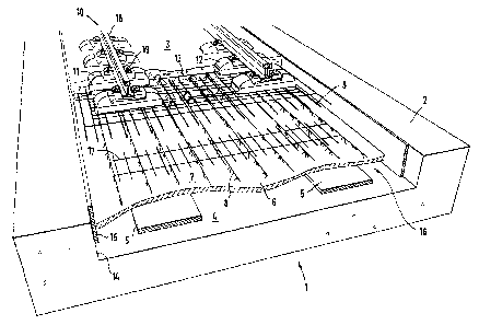
Fixed track bed for rail vehicles which is mounted on elastic elements, with
the concrete support plate being composed of prefabricated plate elements
and a layer of local concrete located thereon, with the prefabricated plate
elements resting on the elastic elements and forming a monolithic composite
with the local concrete.


French Abstract

L'invention concerne une voie fixe pour véhicules ferroviaires, posée sur des éléments élastiques, la plaque porteuse (3) en béton étant constituée de plaques (6) préfabriquées sur lesquelles une couche de béton est coulée sur site, les plaques préfabriquées reposant sur les éléments élastiques et formant un composite monolithique avec le béton coulé sur site.

Claims

Note: Claims are shown in the official language in which they were submitted.


6
CLAIMS
1. A fixed carriageway for rail vehicles, comprising:
a trough having opposing side surfaces and a trough bottom
surface;
a plurality of resilient elements supported on said trough bottom
surface;
a plurality of concrete support panels formed prefabricated
before installation in said trough so as to each have a panel top
surface, a panel bottom surface, and at least one connecting
reinforcing member projecting above the panel top surface;
the plurality of concrete support panels being disposed
supported on the plurality of resilient elements via the panel
bottom surfaces; and
a layer of in-situ concrete being applied on the panel top
surfaces so as to envelop portions of the plurality of resilient
elements projecting above the panel top surfaces such that a
monolithic bond is formed with the in-situ concrete.
2. The fixed carriageway according to claim 1, wherein at least one of the
plurality of concrete support panels has a reinforcement.
3. The fixed carriageway according to claim 1, further comprising a
plurality of butt joints at mutually adjacent ones of the concrete support
panels; and, at said butt joints, an additional reinforcement structure is
provided above the panel top surfaces and enveloped by the mutually
adjacent ones of the concrete support panels.
4. The fixed carriageway according to claim 3, further comprising a
plurality of sleeper blocks, wherein the plurality of resilient elements form
an
all-over support disposed under the plurality of sleeper blocks.
5. The fixed carriageway according to claim 3, , further comprising a
plurality of sleeper blocks, wherein the plurality of resilient elements form
strip
bearings disposed under the plurality of sleeper blocks.

6a
6. The fixed carriageway according to claim 3, , further comprising a
plurality of sleeper blocks, wherein the plurality of resilient elements form
individual bearings disposed under the plurality of sleeper blocks.
7. The fixed carriageway according to claim 3, wherein the plurality of
resilient elements are spiral springs.
8. The fixed carriageway according to claim 3, wherein the monolithic
bond is further generated by adhesion of the panel top surfaces of the
plurality
of concrete support panels to the layer of in-situ concrete.
9. The fixed carriageway according to claim 3, wherein the monolithic
bond is generated by mechanical connections of the layer of in-situ concrete
formed by the envelopment of the portions of the reinforcing members
projecting above the panel top surfaces.
10. The fixed carriageway according to claim 1, , further comprising a
plurality of sleeper blocks, wherein the plurality of resilient elements form
an
all-over support disposed under the plurality of sleeper blocks.
11. The fixed carriageway according to claim 1, , further comprising a
plurality of sleeper blocks, wherein the plurality of resilient elements form
strip
bearings disposed under the plurality of sleeper blocks.
12. The fixed carriageway according to claim 1, , further comprising a
plurality of sleeper blocks, wherein the plurality of resilient elements form
individual bearings disposed under the plurality of sleeper blocks.
13. The fixed carriageway according to claim 1, wherein the plurality of
resilient elements are spiral springs.
14. The fixed carriageway according to claim 1, wherein the monolithic bond
is further generated by adhesion of the panel top surfaces of the plurality of
concrete support panels to the layer of in-situ concrete.

6b
15. The fixed carriageway according to claim 1, further comprising:
each of said plurality of concrete support panels having the panel
bottom surface supported above said trough bottom surface by the
plurality of resilient members so as to define a cavity between said
trough bottom surface and said plurality of concrete support panels;
and a plurality of resilient side panels disposed between the trough
side walls and opposing edges of the concrete support panels, said
plurality of resilient side panels being so configured as to prevent
penetration of concrete into the cavity during formation of the layer of
in-situ concrete.
16. The fixed carriageway according to claim 15, wherein the panel bottom
surfaces have horizontal contact areas contacting the plurality of resilient
members, and the horizontal contact areas are disposed in a uniform
predefined relationship relative remaining portions of the panel bottom
surfaces during the prefabrication of the plurality of concrete support
panels.
17. The fixed carriageway according to claim 16, wherein the uniform
predefined relationship is even with remaining horizontal portions of the
bottom panel surfaces which are adjacent the horizontal contact areas.
18. The fixed carriageway according to claim 17, wherein the bottom panel
surfaces including the horizontal contact areas are flat.

Description

Note: Descriptions are shown in the official language in which they were submitted.


CA 02592757 2010-01-20
FIXED TRACK BED FOR RAIL VEHICLES
FIELD OF THE INVENTION
The invention relates to a fixed carriageway for rail vehicles which is
mounted
on resilient elements.
BACKGROUND
When rail vehicles pass over carriageways, vibrations are generated which
are transmitted through the subsoil and can thus be noticed even in adjacent
buildings. In order to reduce or completely eliminate such unwanted
vibrations, it is already known to configure the carriageway as a sprung-mass
system. The carriageway is in this case formed as a separate vibratable
mass, which is mounted movably with respect to the subsoil via a resilient
element acting as a spring. The resilient element, which is disposed between
the vibratable carriageway and the subsoil, e.g. a tunnel structure, in this
case
effects decoupling of the vibrations, so that the size of the vibrations
transferred to the subsoil does not exceed a certain level.
The assembly of a carriageway by the in-situ method of construction with pre-
placed resilient elements is however relatively expensive in practice, since
an
expensive casing has to be produced around the area to be filled with the
fluid
in-situ concrete in order that, when the in-situ concrete is cast, no rigid
connections form between the substructure and the concrete support panel
which may act as sound-transmission bridges. The assembly of a
carriageway by the in-situ method of construction with subsequently placed
resilient elements is also relatively expensive in practice since the concrete
support panel is conventionally hydraulically lifted in sections and then the
resilient elements are positioned under the concrete support panel. Both
methods are time-consuming and lead to considerable cost.
SUMMARY OF THE INVENTION
It is therefore desirable to indicate a fixed carriageway for rail vehicles
whose
manufacture can be made simpler and more cost-effective.
It is disclosed that, in a fixed carriageway of the type mentioned in the
introduction it is proposed that the concrete support panel may consist of

CA 02592757 2010-01-20
2
prefabricated panels and a layer of in-situ concrete resting thereon, the
prefabricated panels resting on the resilient elements and forming a
monolithic bond with the in-situ concrete.
In accordance with an aspect of the present invention, there is provided a
fixed carriageway for rail vehicles, comprising a trough having opposing side
surfaces and a trough bottom surface; a plurality of resilient elements
supported on the trough bottom surface; a plurality of concrete support panels
formed prefabricated before installation in the trough so as to each have a
panel top surface, a panel bottom surface, and at least one connecting
reinforcing member projecting above the panel top surface; the plurality of
concrete support panels being disposed supported on the plurality of resilient
elements via the panel bottom surfaces; and a layer of in-situ concrete being
applied on the panel top surfaces so as to envelop portions of the plurality
of
resilient elements projecting above the panel top surfaces such that a
monolithic bond is formed with the in-situ concrete.
It has been appreciated that prefabricated panels can be used which form the
bottom-most layer of the vibratable sprung-mass system and simultaneously
form a casing for the concreting of the concrete support panel. The
prefabricated panel may in this case placed on the resilient elements, and
then the concrete support panel is concreted. Thus the stage necessary
hitherto of forming casing for the concrete support panel becomes
superfluous. In the same way, the subsequent lifting of the concreted conrete
support panel becomes superfluous, since the resilient elements have already
been positioned in the right place in advance.
The prefabricated panel may have its own reinforcement, in particular it may
have a connecting reinforcement, which in the installed state forms a bond
with the concrete support panel. If necessary, further reinforcement inserts
can be laid on the prefabricated panel, which after concreting of the concrete
support panel are located in its lower region. By the connecting reinforcement
mentioned, a bond is created between the prefabricated panel and the
concrete support panel.
In order to achieve good force-transmission in the region of mutually abutting
prefabricated panels, at the butt joints an additional reinforcement can be

CA 02592757 2010-01-20
3
disposed. This reinforcement can be formed as a reinforcement mesh, whose
reinforcement rods disposed in the longitudinal direction respectively cover
the butt joints.
The resilient elements of the fixed carriageway can form an all-over support,
or alternatively they can be formed as strip bearings, which are preferably
disposed under sleeper blocks. In most cases, strip-like resilient elements
suffice and are generally advantageous.
As a further alternative, in the fixed carriageway, resilient elements in the
form
of springs may be considered, in particular these may take the form of spiral
springs.
A particularly good vibration damping effect can be achieved if the concrete
support panel is mounted resiliently in a trough. On the base of the trough
are
the resilient elements, on which the concrete support panel is laid. Since the
concrete support panel can move relative to the trough, the desired
technological decoupling of vibration is achieved. By the controlled selection
of the mass of the concrete support panel and of the properties of the
resilient
elements, vibrations of a certain frequency range can be suppressed in a
controlled manner.
BRIEF DESCRIPTION OF THE DRAWINGS
In the figures which illustrate embodiments of the invention by example only,
FIG. 1 a perspective diagram partially in section of a fixed carriageway
according to the invention; and
FIG. 2 a section through the fixed carriageway shown in FIG. 1 transverse to
the direction of travel.
DETAILED DESCRIPTION
The fixed carriageway shown in FIG. 1 is used in a tunnel and comprises a
trough 2, in which a concrete support panel 3 is resiliently mounted. At the
same time, reference is made to FIG. 2, which shows a section through the
fixed carriageway 1 shown in FIG. 1 transverse to the direction of travel.

CA 02592757 2007-07-04
4
In manufacturing the fixed carriageway 1, resilient elements formed as strip
bearings 5 and consisting of elastomer material are laid on the base face 4 of
the trough 2.
On the resilient elements, a prefabricated panel 6 is laid, which has on its
upper
face 7 a projecting connecting reinforcement 8. Additionally laid and aligned
on
the prefabricated panel 6 are longitudinal reinforcements 9 and optionally
transverse reinforcements (not shown) as well as sleepers 10, which are
assembled to form a track grid with rail fixings 19, rails 18 and longitudinal
reinforcements 9. In the example shown, dual-block sleepers are used, whose
sleeper blocks 11, 12 are respectively connected together via a grid support
13.
In the region of the butt joints of mutually abutting prefabricated panels 6,
an
additional reinforcement 17 overlapping the butt joint is laid.
On the side walls 14 of the trough 2, resilient elements 15 acting as side
casings are mounted, which prevent the penetration of concrete into cavities
16
below the prefabricated panel 6.
By concreting, the concrete panel 3 is formed, a bond of the concrete support
panel 3 with the prefabricated panel 6 being produced by the connecting
reinforcement 8 on the upper face 7 of the prefabricated panel 6. By the
penetration of the fluid in-situ concrete, the sleepers 10 are embedded in the
concrete support panel 3, so that only the upper region of the sleeper blocks
11,
12 projects from the concrete support panel 3.
The concrete support panel 3 forms a vibratable mass with respect to the
trough
2, whose vibration behaviour can be adapted over a wide range by the mass of
the concrete support panel 3 and the properties of the strip bearings 5. To
this
end, the width, thickness or material of the strip bearings 5 can be varied
accordingly, as well as the mass of the concrete support panel 3. Thus the
desired advantageous vibration behaviour can be achieved, so that when a rail

CA 02592757 2007-07-04
vehicle passes over the fixed carriageway 1, the vibrations caused thereby are
barely, if at all, transmitted to the trough 2 and the surroundings.

Representative Drawing
A single figure which represents the drawing illustrating the invention.
Administrative Status

2024-08-01:As part of the Next Generation Patents (NGP) transition, the Canadian Patents Database (CPD) now contains a more detailed Event History, which replicates the Event Log of our new back-office solution.

Please note that "Inactive:" events refers to events no longer in use in our new back-office solution.

For a clearer understanding of the status of the application/patent presented on this page, the site Disclaimer , as well as the definitions for Patent , Event History , Maintenance Fee  and Payment History  should be consulted.

Event History

Description Date
Maintenance Request Received 2024-10-01
Maintenance Fee Payment Determined Compliant 2024-10-01
Common Representative Appointed 2019-10-30
Letter Sent 2018-05-03
Inactive: Multiple transfers 2018-04-19
Change of Address or Method of Correspondence Request Received 2018-03-28
Grant by Issuance 2010-12-07
Inactive: Cover page published 2010-12-06
Pre-grant 2010-09-20
Inactive: Final fee received 2010-09-20
Letter Sent 2010-04-06
Notice of Allowance is Issued 2010-04-06
Inactive: Approved for allowance (AFA) 2010-03-29
Amendment Received - Voluntary Amendment 2010-01-20
Inactive: S.30(2) Rules - Examiner requisition 2009-07-20
Letter Sent 2008-04-14
Inactive: Correspondence - Prosecution 2008-03-20
Inactive: Correspondence - Prosecution 2008-01-21
Inactive: Cover page published 2007-09-21
Inactive: Notice - National entry - No RFE 2007-09-19
Inactive: First IPC assigned 2007-08-01
Application Received - PCT 2007-07-31
Request for Examination Received 2007-07-19
All Requirements for Examination Determined Compliant 2007-07-19
Request for Examination Requirements Determined Compliant 2007-07-19
National Entry Requirements Determined Compliant 2007-07-04
Application Published (Open to Public Inspection) 2007-05-24

Abandonment History

There is no abandonment history.

Maintenance Fee

The last payment was received on 2010-09-16

Note : If the full payment has not been received on or before the date indicated, a further fee may be required which may be one of the following

  • the reinstatement fee;
  • the late payment fee; or
  • additional fee to reverse deemed expiry.

Patent fees are adjusted on the 1st of January every year. The amounts above are the current amounts if received by December 31 of the current year.
Please refer to the CIPO Patent Fees web page to see all current fee amounts.

Owners on Record

Note: Records showing the ownership history in alphabetical order.

Current Owners on Record
PCM RAIL.ONE AG
Past Owners on Record
FRANZ HABAN
HEINRICH GALL
MARTIN KOWALSKI
Past Owners that do not appear in the "Owners on Record" listing will appear in other documentation within the application.
Documents

To view selected files, please enter reCAPTCHA code :


To view images, click a link in the Document Description column. To download the documents, select one or more checkboxes in the first column and then click the "Download Selected in PDF format (Zip Archive)" or the "Download Selected as Single PDF" button.

List of published and non-published patent-specific documents on the CPD .

If you have any difficulty accessing content, you can call the Client Service Centre at 1-866-997-1936 or send them an e-mail at CIPO Client Service Centre.


Document
Description 
Date
(yyyy-mm-dd) 
Number of pages   Size of Image (KB) 
Description 2007-07-03 5 179
Claims 2007-07-03 1 34
Drawings 2007-07-03 2 56
Abstract 2007-07-03 1 9
Representative drawing 2007-09-19 1 23
Description 2010-01-19 5 189
Claims 2010-01-19 3 108
Abstract 2010-03-30 1 9
Confirmation of electronic submission 2024-09-30 2 66
Notice of National Entry 2007-09-18 1 207
Acknowledgement of Request for Examination 2008-04-13 1 177
Reminder of maintenance fee due 2008-06-15 1 113
Commissioner's Notice - Application Found Allowable 2010-04-05 1 166
PCT 2007-07-03 6 274
Fees 2009-08-19 1 34
Correspondence 2010-09-19 1 37
Fees 2010-09-15 1 41