Sélection de la langue

Search

Sommaire du brevet 2592757 

Énoncé de désistement de responsabilité concernant l'information provenant de tiers

Une partie des informations de ce site Web a été fournie par des sources externes. Le gouvernement du Canada n'assume aucune responsabilité concernant la précision, l'actualité ou la fiabilité des informations fournies par les sources externes. Les utilisateurs qui désirent employer cette information devraient consulter directement la source des informations. Le contenu fourni par les sources externes n'est pas assujetti aux exigences sur les langues officielles, la protection des renseignements personnels et l'accessibilité.

Disponibilité de l'Abrégé et des Revendications

L'apparition de différences dans le texte et l'image des Revendications et de l'Abrégé dépend du moment auquel le document est publié. Les textes des Revendications et de l'Abrégé sont affichés :

  • lorsque la demande peut être examinée par le public;
  • lorsque le brevet est émis (délivrance).
(12) Brevet: (11) CA 2592757
(54) Titre français: VOIE FIXE POUR VEHICULES FERROVIAIRES
(54) Titre anglais: FIXED TRACK BED FOR RAIL VEHICLES
Statut: Accordé et délivré
Données bibliographiques
(51) Classification internationale des brevets (CIB):
  • E01B 01/00 (2006.01)
(72) Inventeurs :
  • KOWALSKI, MARTIN (Allemagne)
  • GALL, HEINRICH (Allemagne)
  • HABAN, FRANZ (Allemagne)
(73) Titulaires :
  • PCM RAIL.ONE AG
(71) Demandeurs :
  • PCM RAIL.ONE AG (Allemagne)
(74) Agent: SMART & BIGGAR LP
(74) Co-agent:
(45) Délivré: 2010-12-07
(86) Date de dépôt PCT: 2006-10-12
(87) Mise à la disponibilité du public: 2007-05-24
Requête d'examen: 2007-07-19
Licence disponible: S.O.
Cédé au domaine public: S.O.
(25) Langue des documents déposés: Anglais

Traité de coopération en matière de brevets (PCT): Oui
(86) Numéro de la demande PCT: PCT/DE2006/001792
(87) Numéro de publication internationale PCT: DE2006001792
(85) Entrée nationale: 2007-07-04

(30) Données de priorité de la demande:
Numéro de la demande Pays / territoire Date
10 2005 054 820.2 (Allemagne) 2005-11-15

Abrégés

Abrégé français

L'invention concerne une voie fixe pour véhicules ferroviaires, posée sur des éléments élastiques, la plaque porteuse (3) en béton étant constituée de plaques (6) préfabriquées sur lesquelles une couche de béton est coulée sur site, les plaques préfabriquées reposant sur les éléments élastiques et formant un composite monolithique avec le béton coulé sur site.


Abrégé anglais


Fixed track bed for rail vehicles which is mounted on elastic elements, with
the concrete support plate being composed of prefabricated plate elements
and a layer of local concrete located thereon, with the prefabricated plate
elements resting on the elastic elements and forming a monolithic composite
with the local concrete.

Revendications

Note : Les revendications sont présentées dans la langue officielle dans laquelle elles ont été soumises.


6
CLAIMS
1. A fixed carriageway for rail vehicles, comprising:
a trough having opposing side surfaces and a trough bottom
surface;
a plurality of resilient elements supported on said trough bottom
surface;
a plurality of concrete support panels formed prefabricated
before installation in said trough so as to each have a panel top
surface, a panel bottom surface, and at least one connecting
reinforcing member projecting above the panel top surface;
the plurality of concrete support panels being disposed
supported on the plurality of resilient elements via the panel
bottom surfaces; and
a layer of in-situ concrete being applied on the panel top
surfaces so as to envelop portions of the plurality of resilient
elements projecting above the panel top surfaces such that a
monolithic bond is formed with the in-situ concrete.
2. The fixed carriageway according to claim 1, wherein at least one of the
plurality of concrete support panels has a reinforcement.
3. The fixed carriageway according to claim 1, further comprising a
plurality of butt joints at mutually adjacent ones of the concrete support
panels; and, at said butt joints, an additional reinforcement structure is
provided above the panel top surfaces and enveloped by the mutually
adjacent ones of the concrete support panels.
4. The fixed carriageway according to claim 3, further comprising a
plurality of sleeper blocks, wherein the plurality of resilient elements form
an
all-over support disposed under the plurality of sleeper blocks.
5. The fixed carriageway according to claim 3, , further comprising a
plurality of sleeper blocks, wherein the plurality of resilient elements form
strip
bearings disposed under the plurality of sleeper blocks.

6a
6. The fixed carriageway according to claim 3, , further comprising a
plurality of sleeper blocks, wherein the plurality of resilient elements form
individual bearings disposed under the plurality of sleeper blocks.
7. The fixed carriageway according to claim 3, wherein the plurality of
resilient elements are spiral springs.
8. The fixed carriageway according to claim 3, wherein the monolithic
bond is further generated by adhesion of the panel top surfaces of the
plurality
of concrete support panels to the layer of in-situ concrete.
9. The fixed carriageway according to claim 3, wherein the monolithic
bond is generated by mechanical connections of the layer of in-situ concrete
formed by the envelopment of the portions of the reinforcing members
projecting above the panel top surfaces.
10. The fixed carriageway according to claim 1, , further comprising a
plurality of sleeper blocks, wherein the plurality of resilient elements form
an
all-over support disposed under the plurality of sleeper blocks.
11. The fixed carriageway according to claim 1, , further comprising a
plurality of sleeper blocks, wherein the plurality of resilient elements form
strip
bearings disposed under the plurality of sleeper blocks.
12. The fixed carriageway according to claim 1, , further comprising a
plurality of sleeper blocks, wherein the plurality of resilient elements form
individual bearings disposed under the plurality of sleeper blocks.
13. The fixed carriageway according to claim 1, wherein the plurality of
resilient elements are spiral springs.
14. The fixed carriageway according to claim 1, wherein the monolithic bond
is further generated by adhesion of the panel top surfaces of the plurality of
concrete support panels to the layer of in-situ concrete.

6b
15. The fixed carriageway according to claim 1, further comprising:
each of said plurality of concrete support panels having the panel
bottom surface supported above said trough bottom surface by the
plurality of resilient members so as to define a cavity between said
trough bottom surface and said plurality of concrete support panels;
and a plurality of resilient side panels disposed between the trough
side walls and opposing edges of the concrete support panels, said
plurality of resilient side panels being so configured as to prevent
penetration of concrete into the cavity during formation of the layer of
in-situ concrete.
16. The fixed carriageway according to claim 15, wherein the panel bottom
surfaces have horizontal contact areas contacting the plurality of resilient
members, and the horizontal contact areas are disposed in a uniform
predefined relationship relative remaining portions of the panel bottom
surfaces during the prefabrication of the plurality of concrete support
panels.
17. The fixed carriageway according to claim 16, wherein the uniform
predefined relationship is even with remaining horizontal portions of the
bottom panel surfaces which are adjacent the horizontal contact areas.
18. The fixed carriageway according to claim 17, wherein the bottom panel
surfaces including the horizontal contact areas are flat.

Description

Note : Les descriptions sont présentées dans la langue officielle dans laquelle elles ont été soumises.

CA 02592757 2010-01-20
FIXED TRACK BED FOR RAIL VEHICLES
FIELD OF THE INVENTION
The invention relates to a fixed carriageway for rail vehicles which is
mounted
on resilient elements.
BACKGROUND
When rail vehicles pass over carriageways, vibrations are generated which
are transmitted through the subsoil and can thus be noticed even in adjacent
buildings. In order to reduce or completely eliminate such unwanted
vibrations, it is already known to configure the carriageway as a sprung-mass
system. The carriageway is in this case formed as a separate vibratable
mass, which is mounted movably with respect to the subsoil via a resilient
element acting as a spring. The resilient element, which is disposed between
the vibratable carriageway and the subsoil, e.g. a tunnel structure, in this
case
effects decoupling of the vibrations, so that the size of the vibrations
transferred to the subsoil does not exceed a certain level.
The assembly of a carriageway by the in-situ method of construction with pre-
placed resilient elements is however relatively expensive in practice, since
an
expensive casing has to be produced around the area to be filled with the
fluid
in-situ concrete in order that, when the in-situ concrete is cast, no rigid
connections form between the substructure and the concrete support panel
which may act as sound-transmission bridges. The assembly of a
carriageway by the in-situ method of construction with subsequently placed
resilient elements is also relatively expensive in practice since the concrete
support panel is conventionally hydraulically lifted in sections and then the
resilient elements are positioned under the concrete support panel. Both
methods are time-consuming and lead to considerable cost.
SUMMARY OF THE INVENTION
It is therefore desirable to indicate a fixed carriageway for rail vehicles
whose
manufacture can be made simpler and more cost-effective.
It is disclosed that, in a fixed carriageway of the type mentioned in the
introduction it is proposed that the concrete support panel may consist of

CA 02592757 2010-01-20
2
prefabricated panels and a layer of in-situ concrete resting thereon, the
prefabricated panels resting on the resilient elements and forming a
monolithic bond with the in-situ concrete.
In accordance with an aspect of the present invention, there is provided a
fixed carriageway for rail vehicles, comprising a trough having opposing side
surfaces and a trough bottom surface; a plurality of resilient elements
supported on the trough bottom surface; a plurality of concrete support panels
formed prefabricated before installation in the trough so as to each have a
panel top surface, a panel bottom surface, and at least one connecting
reinforcing member projecting above the panel top surface; the plurality of
concrete support panels being disposed supported on the plurality of resilient
elements via the panel bottom surfaces; and a layer of in-situ concrete being
applied on the panel top surfaces so as to envelop portions of the plurality
of
resilient elements projecting above the panel top surfaces such that a
monolithic bond is formed with the in-situ concrete.
It has been appreciated that prefabricated panels can be used which form the
bottom-most layer of the vibratable sprung-mass system and simultaneously
form a casing for the concreting of the concrete support panel. The
prefabricated panel may in this case placed on the resilient elements, and
then the concrete support panel is concreted. Thus the stage necessary
hitherto of forming casing for the concrete support panel becomes
superfluous. In the same way, the subsequent lifting of the concreted conrete
support panel becomes superfluous, since the resilient elements have already
been positioned in the right place in advance.
The prefabricated panel may have its own reinforcement, in particular it may
have a connecting reinforcement, which in the installed state forms a bond
with the concrete support panel. If necessary, further reinforcement inserts
can be laid on the prefabricated panel, which after concreting of the concrete
support panel are located in its lower region. By the connecting reinforcement
mentioned, a bond is created between the prefabricated panel and the
concrete support panel.
In order to achieve good force-transmission in the region of mutually abutting
prefabricated panels, at the butt joints an additional reinforcement can be

CA 02592757 2010-01-20
3
disposed. This reinforcement can be formed as a reinforcement mesh, whose
reinforcement rods disposed in the longitudinal direction respectively cover
the butt joints.
The resilient elements of the fixed carriageway can form an all-over support,
or alternatively they can be formed as strip bearings, which are preferably
disposed under sleeper blocks. In most cases, strip-like resilient elements
suffice and are generally advantageous.
As a further alternative, in the fixed carriageway, resilient elements in the
form
of springs may be considered, in particular these may take the form of spiral
springs.
A particularly good vibration damping effect can be achieved if the concrete
support panel is mounted resiliently in a trough. On the base of the trough
are
the resilient elements, on which the concrete support panel is laid. Since the
concrete support panel can move relative to the trough, the desired
technological decoupling of vibration is achieved. By the controlled selection
of the mass of the concrete support panel and of the properties of the
resilient
elements, vibrations of a certain frequency range can be suppressed in a
controlled manner.
BRIEF DESCRIPTION OF THE DRAWINGS
In the figures which illustrate embodiments of the invention by example only,
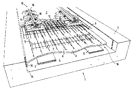
FIG. 1 a perspective diagram partially in section of a fixed carriageway
according to the invention; and
FIG. 2 a section through the fixed carriageway shown in FIG. 1 transverse to
the direction of travel.
DETAILED DESCRIPTION
The fixed carriageway shown in FIG. 1 is used in a tunnel and comprises a
trough 2, in which a concrete support panel 3 is resiliently mounted. At the
same time, reference is made to FIG. 2, which shows a section through the
fixed carriageway 1 shown in FIG. 1 transverse to the direction of travel.

CA 02592757 2007-07-04
4
In manufacturing the fixed carriageway 1, resilient elements formed as strip
bearings 5 and consisting of elastomer material are laid on the base face 4 of
the trough 2.
On the resilient elements, a prefabricated panel 6 is laid, which has on its
upper
face 7 a projecting connecting reinforcement 8. Additionally laid and aligned
on
the prefabricated panel 6 are longitudinal reinforcements 9 and optionally
transverse reinforcements (not shown) as well as sleepers 10, which are
assembled to form a track grid with rail fixings 19, rails 18 and longitudinal
reinforcements 9. In the example shown, dual-block sleepers are used, whose
sleeper blocks 11, 12 are respectively connected together via a grid support
13.
In the region of the butt joints of mutually abutting prefabricated panels 6,
an
additional reinforcement 17 overlapping the butt joint is laid.
On the side walls 14 of the trough 2, resilient elements 15 acting as side
casings are mounted, which prevent the penetration of concrete into cavities
16
below the prefabricated panel 6.
By concreting, the concrete panel 3 is formed, a bond of the concrete support
panel 3 with the prefabricated panel 6 being produced by the connecting
reinforcement 8 on the upper face 7 of the prefabricated panel 6. By the
penetration of the fluid in-situ concrete, the sleepers 10 are embedded in the
concrete support panel 3, so that only the upper region of the sleeper blocks
11,
12 projects from the concrete support panel 3.
The concrete support panel 3 forms a vibratable mass with respect to the
trough
2, whose vibration behaviour can be adapted over a wide range by the mass of
the concrete support panel 3 and the properties of the strip bearings 5. To
this
end, the width, thickness or material of the strip bearings 5 can be varied
accordingly, as well as the mass of the concrete support panel 3. Thus the
desired advantageous vibration behaviour can be achieved, so that when a rail

CA 02592757 2007-07-04
vehicle passes over the fixed carriageway 1, the vibrations caused thereby are
barely, if at all, transmitted to the trough 2 and the surroundings.

Dessin représentatif
Une figure unique qui représente un dessin illustrant l'invention.
États administratifs

2024-08-01 : Dans le cadre de la transition vers les Brevets de nouvelle génération (BNG), la base de données sur les brevets canadiens (BDBC) contient désormais un Historique d'événement plus détaillé, qui reproduit le Journal des événements de notre nouvelle solution interne.

Veuillez noter que les événements débutant par « Inactive : » se réfèrent à des événements qui ne sont plus utilisés dans notre nouvelle solution interne.

Pour une meilleure compréhension de l'état de la demande ou brevet qui figure sur cette page, la rubrique Mise en garde , et les descriptions de Brevet , Historique d'événement , Taxes périodiques et Historique des paiements devraient être consultées.

Historique d'événement

Description Date
Requête visant le maintien en état reçue 2024-10-01
Paiement d'une taxe pour le maintien en état jugé conforme 2024-10-01
Représentant commun nommé 2019-10-30
Lettre envoyée 2018-05-03
Inactive : Transferts multiples 2018-04-19
Requête pour le changement d'adresse ou de mode de correspondance reçue 2018-03-28
Accordé par délivrance 2010-12-07
Inactive : Page couverture publiée 2010-12-06
Préoctroi 2010-09-20
Inactive : Taxe finale reçue 2010-09-20
Lettre envoyée 2010-04-06
Un avis d'acceptation est envoyé 2010-04-06
Inactive : Approuvée aux fins d'acceptation (AFA) 2010-03-29
Modification reçue - modification volontaire 2010-01-20
Inactive : Dem. de l'examinateur par.30(2) Règles 2009-07-20
Lettre envoyée 2008-04-14
Inactive : Correspondance - Poursuite 2008-03-20
Inactive : Correspondance - Poursuite 2008-01-21
Inactive : Page couverture publiée 2007-09-21
Inactive : Notice - Entrée phase nat. - Pas de RE 2007-09-19
Inactive : CIB en 1re position 2007-08-01
Demande reçue - PCT 2007-07-31
Requête d'examen reçue 2007-07-19
Toutes les exigences pour l'examen - jugée conforme 2007-07-19
Exigences pour une requête d'examen - jugée conforme 2007-07-19
Exigences pour l'entrée dans la phase nationale - jugée conforme 2007-07-04
Demande publiée (accessible au public) 2007-05-24

Historique d'abandonnement

Il n'y a pas d'historique d'abandonnement

Taxes périodiques

Le dernier paiement a été reçu le 2010-09-16

Avis : Si le paiement en totalité n'a pas été reçu au plus tard à la date indiquée, une taxe supplémentaire peut être imposée, soit une des taxes suivantes :

  • taxe de rétablissement ;
  • taxe pour paiement en souffrance ; ou
  • taxe additionnelle pour le renversement d'une péremption réputée.

Les taxes sur les brevets sont ajustées au 1er janvier de chaque année. Les montants ci-dessus sont les montants actuels s'ils sont reçus au plus tard le 31 décembre de l'année en cours.
Veuillez vous référer à la page web des taxes sur les brevets de l'OPIC pour voir tous les montants actuels des taxes.

Titulaires au dossier

Les titulaires actuels et antérieures au dossier sont affichés en ordre alphabétique.

Titulaires actuels au dossier
PCM RAIL.ONE AG
Titulaires antérieures au dossier
FRANZ HABAN
HEINRICH GALL
MARTIN KOWALSKI
Les propriétaires antérieurs qui ne figurent pas dans la liste des « Propriétaires au dossier » apparaîtront dans d'autres documents au dossier.
Documents

Pour visionner les fichiers sélectionnés, entrer le code reCAPTCHA :


Pour visualiser une image, cliquer sur un lien dans la colonne description du document. Pour télécharger l'image (les images), cliquer l'une ou plusieurs cases à cocher dans la première colonne et ensuite cliquer sur le bouton "Télécharger sélection en format PDF (archive Zip)" ou le bouton "Télécharger sélection (en un fichier PDF fusionné)".

Liste des documents de brevet publiés et non publiés sur la BDBC .

Si vous avez des difficultés à accéder au contenu, veuillez communiquer avec le Centre de services à la clientèle au 1-866-997-1936, ou envoyer un courriel au Centre de service à la clientèle de l'OPIC.


Description du
Document 
Date
(aaaa-mm-jj) 
Nombre de pages   Taille de l'image (Ko) 
Description 2007-07-03 5 179
Revendications 2007-07-03 1 34
Dessins 2007-07-03 2 56
Abrégé 2007-07-03 1 9
Dessin représentatif 2007-09-19 1 23
Description 2010-01-19 5 189
Revendications 2010-01-19 3 108
Abrégé 2010-03-30 1 9
Confirmation de soumission électronique 2024-09-30 2 66
Avis d'entree dans la phase nationale 2007-09-18 1 207
Accusé de réception de la requête d'examen 2008-04-13 1 177
Rappel de taxe de maintien due 2008-06-15 1 113
Avis du commissaire - Demande jugée acceptable 2010-04-05 1 166
PCT 2007-07-03 6 274
Taxes 2009-08-19 1 34
Correspondance 2010-09-19 1 37
Taxes 2010-09-15 1 41