Note: Descriptions are shown in the official language in which they were submitted.
CA 02592769 2007-06-26
INTAKE STRUCTURE OF V-TYPE INTERNAL COMBUSTION ENGINE
FIELD OF THE INVENTION
The present invention relates to a structure of an intake device of a V-type
internal combustion engine.
BACKGROUND OF THE INVENTION
Heretofore, in a V-type internal combustion engine, an intake device that
performs intakes of front and rear cylinders has been disposed in a V-bank
between the cylinders. However, the space in the V-bank is narrow, and the
temperature in the space is high, and accordingly, the space for placing the
intake
device is limited. Heretofore, the intake device has been disposed above the V-
bank, and accordingly, the overall height of the internal combustion engine
has
become high (for example, refer to Japanese Patent No. 3106724 (Fig. 1).
It is an object of the present invention to provide such a structure of an
intake
device that does not allow the overall height of the internal combustion
engine to
become high.
SUMMARY OF THE INVENTION
A first aspect of the invention relates to an intake structure of a V-type
internal
combustion engine in which an intake manifold that performs intakes of front
and rear cylinders is placed in a V-bank. The intake structure is
characterized in
that a throttle body including a throttle opening sensor on one end of a
throttle
WH 13185/cs
CA 02592769 2007-06-26
-2-
valve shaft is provided so that an intake passage of the throttle body can be
extended in a crankshaft direction between the front and rear cylinders, the
center of the intake passage of the throttle body is disposed to be shifted to
one
cylinder side, and the throttle opening sensor is placed on a side where the
center
of the intake passage of the throttle body is apart from the cylinder.
A second aspect of the invention provides the intake structure of a V-type
internal combustion engine according to the first aspect, characterized in
that, in
the intake manifold, the center of the intake passage is disposed to be
shifted to
the one cylinder side with respect to the center position between front and
rear
injection valves, and the thickness of a coupling flange portion to the engine
on
the side where the center of the intake passage is apart from the cylinder is
made
thicker than on other sides.
An invention according to the third aspect of the invention is the intake
structure
of a V-type internal combustion engine according to the second aspect,
characterized in that the internal combustion engine is an SOHC type internal
combustion engine with a V-bank angle of 90 degrees or less.
With the first aspect of the invention, the throttle opening sensor is placed
on the
side where the center of the intake passage is apart from the cylinder, and is
isolated from the cylinder, thereby being able to be protected from heat from
the
engine.
With the second aspect of the invention, the center of the intake passage is
disposed to be shifted to the one cylinder side, and accordingly, the
thickness of
the coupling flange portion can be made thick on the side where a gap with the
cylinder is increased, and it becomes easy to manufacture the intake manifold,
hence productivity is enhanced.
With the third aspect of the invention, the intake device is placed in a
narrow
space of the V-bank, thus making it possible to lower the overall height of
the
internal combustion engine.
WH 13185/cs
CA 02592769 2007-06-26
-3-
BRIEF DESCRIPTION OF THE DRAWINGS
Preferred embodiments of the invention are shown in the drawings, wherein:
Fig. 1 is a top view showing a state where an intake structure according to
the
present invention is attached onto cylinders of a V-type internal combustion
engine.
Fig. 2 is a side view of cylinder portions of the V-type internal combustion
engine
including an intake manifold 3 of the intake structure.
Fig. 3 is a side view of the cylinder portions of the V-type internal
combustion
engine including the intake structure, showing a state where a throttle body 4
is
attached onto the intake manifold 3.
Fig. 4 is a top view of the intake manifold 3.
Fig. 5 is a sectional view taken along arrow V of Fig. 4.
Fig. 6 is a perspective view of the intake manifold 3.
Fig. 7 is a top view of the throttle body 4.
Fig. 8 is a view on arrow IIIV of Fig. 7.
Fig. 9 is a cross-sectional view taken along a line IX-IX of Fig. 8.
Fig. 10 is a side view of main portion showing a state where the V-type
internal
combustion engine E of this embodiment, which includes the intake structure,
is
mounted on a motorcycle.
WH 13185/cs
CA 02592769 2007-06-26
-4-
DETAILED DESCRIPTION OF THE PREFERRED EMBODIMENTS
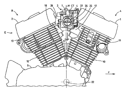
Fig. 1 is a top view showing a state where an intake structure according to
the
present invention is attached onto cylinders of a V-type internal combustion
engine E. Reference symbol L denotes a centerline of the internal combustion
engine in a fore and aft direction. Arrow F is parallel to the centerline in
the fore
and aft direction, and indicates forward in the traveling direction of a
vehicle.
This internal combustion engine is an SOHC type internal combustion engine
with a V-bank angle of 52 degrees, and is mounted on a motorcycle. In the
drawing, reference symbol A denotes a front cylinder, reference symbol B
denotes a rear cylinder, reference numeral 1 denotes a front head cover,
reference
numeral 2 denotes a rear head cover, reference numeral 11 denotes a front
cylinder head, and reference numeral 13 denotes a rear cylinder head.
In the drawing, an intake manifold 3 and a throttle body 4 are attached
between
both of the cylinder heads 11 and 13. Branch passages of the intake manifold 3
are attached to intake ports of the cylinder heads 11 and 13, and the throttle
body
4 is attached to the intake manifold 3. The throttle body 4 is extended from
one
side of the intake manifold 3 to a right side in the traveling direction of
the
vehicle. An air cleaner 24 is disposed on a right side of the cylinders. An
air
cleaner attachment portion opening 25 on a right end of the throttle body 4 is
connected to the air cleaner 24. A front fuel injection valve 5 and a rear
fuel
injection valve 6 are mounted on an upper surface of the intake manifold 3. At
a
position equidistant from both of the fuel injection valves, a fuel pipe 7 is
provided perpendicularly to the fore and aft direction.
Fig. 2 is a side view of the main portion of the V-type internal combustion
engine
E including the intake manifold 3 with the above-described intake structure.
In
the drawing, a state is shown, where the throttle body 4 is detached and only
the
intake manifold 3 is mounted. In this internal combustion engine, on a front
side
of an upper surface of a crankcase 9, assembled are a front cylinder block 10,
the
front cylinder head 11 and the front head cover 1, and on a rear side of the
upper
surface, assembled are a rear cylinder block 12, the rear cylinder head 13,
and the
rear head cover 2.
WH 13185/cs
CA 02592769 2007-06-26
-5-
In the front cylinder A of Fig. 2, reference numeral 14 denotes a front spark-
plug
attachment hole, and reference numeral 15 denotes a front exhaust port. In the
rear cylinder B, a rear spark-plug attachment hole is provided on a left side
surface opposite from the side of the front spark-plug attachment hole, and
accordingly, is not shown in the drawing. Reference numeral 16 denotes a rear
exhaust port. On a side where both of the cylinder heads are facing each
other, a
front intake port 17 and a rear intake port 18 are provided, onto which end
portions of the branch sides of the intake manifold 3 are attached while
interposing a front flange 19 and a rear flange 20 therebetween, respectively.
Reference numeral 21 denotes a throttle body attachment portion opening, and
reference symbol CT denotes the center of an intake passage, which is also the
center of the throttle body attachment portion opening 21.
In Fig. 2, reference symbol CA denotes a cylinder centerline of the front
cylinder
A, reference symbol CB denotes a cylinder centerline of the rear cylinder B,
reference symbol 0 denotes an angle made by both of the centerlines when
viewed from the side, that is, the V-bank angle 0. Reference symbol M denotes
a
plane containing a bisector of the V-bank angle 0 and an axis line of a
crankshaft
22, that is, an inter-cylinder center plane. The fuel pipe 7 is provided on
the
inter-cylinder center plane M, and the front fuel injection valve 5 and the
rear
fuel injection valve 6 are individually provided at positions equidistant from
the
inter-cylinder center plane M. The center CT of the throttle body attachment
portion opening 21 is provided to be shifted by a deflection D from the inter-
cylinder center plane M to the front cylinder side.
Fig. 3 is a side view of the main portion of the V-type internal combustion
engine
E including the intake structure, showing a state where the throttle body 4 is
attached onto the intake manifold 3. Reference numeral 25 denotes the air
cleaner attachment portion opening which is provided on the end of the
throttle
body. A centerline of the throttle body, that is, the center CT of the intake
passage is deflected forward, and accordingly, the center of the air cleaner
attachment portion opening is also shifted forward by the deflection D from
the
inter-cylinder center plane M. The center of the intake manifold 3, that is, a
position of the fuel pipe 7 coincides with the inter-cylinder center plane M,
and
WH 13185/cs
CA 02592769 2007-06-26
-6-
accordingly, the intake passage center CT is shifted by the deflection D also
with
respect to the center of the intake manifold. In the inside of the air cleaner
attachment portion opening 25 of Fig. 3, a throttle valve shaft 26 and a
throttle
valve plate 27 are seen. On the rear cylinder B side of the throttle body 4, a
throttle opening sensor 28 is provided, which measures a rotation angle of the
throttle valve shaft 26, and which senses an opening of a throttle. The
position of
the throttle opening sensor 28 is also shown in Fig. 1.
Fig. 4 is a top view of the intake manifold 3, Fig. 5 is a sectional view
taken along
arrow V of Fig. 4, and Fig. 6 is a perspective view of the intake manifold 3.
In
Fig. 4, the fuel pipe 7 is located on the center of an upper portion of the
intake
manifold 3. In front and rear of the fuel pipe 7, the front fuel injection
valve 5
and the rear fuel injection valve 6 are mounted, respectively. Power supply
connection portions 30 and 31 are provided on the fuel injection valves 5 and
6,
respectively. The fuel injection valves 5 and 6 are fixed to the intake
manifold 3
by bolts 32 and 33, respectively.
In Fig. 5, on a lower portion of the intake manifold 3, the front flange 19
and the
rear flange 20 for attaching the intake manifold 3 onto the front and rear
cylinder
heads 11 and 13 are provided. The branch passages of the lower portion of the
intake manifold 3 are connected to the intake ports 17 and 18 (Fig. 2) of the
respective cylinders, and the flanges 19 and 20 are fixed to the vicinities of
the
intake ports 17 and 18 of the respective cylinders 11 and 13 while
individually
interposing bolts inserted into bolt holes 34 and 35 (Fig. 4) therebetween.
In Fig. 6, on the upper portion of the intake manifold 3, there are seen an
attachment hole 36 for the front fuel injection valve 5 and an attachment hole
37
for the rear fuel injection valve 6. In the vicinities of the respective
attachment
holes, screw holes 38 and 39 for the fuel injection valve attachment bolts 32
and
33 (Fig. 4) are provided. In front and rear of the lower portion of the intake
manifold 3, the front flange 19 and the rear flange 20 are seen. Moreover, on
a
foreground side, the throttle body attachment portion opening 21 is seen. In
the
drawing, flows of air, fuel, and an air-fuel mixture are indicated by arrows.
A
rubber coating layer 3b is formed on an outer surface of a metal portion 3a of
the
WH 13185/cs
CA 02592769 2007-06-26
-7-
intake manifold 3. The rubber coating layer 3b is formed by putting the metal
portion 3a into a metal die, injecting molten rubber into a layered space
between
the metal portion and the metal die, and curing the rubber. In such a way,
coating for the intake manifold 3 is omitted. Since a large gap between the
flange
portions of the intake manifold and a connection portion of the throttle body
is
ensured, it is easy to mold the metal die in the case of performing rubber
baking
for the outer surface.
Fig. 7 is a top view of the throttle body 4, Fig. 8 is a sectional view taken
along
arrow IIIV of Fig. 7, and Fig. 9 is a cross-sectional view taken along a line
IX-IX of
Fig. 8. In Fig. 7, the arrow F indicates forward. An upper portion of the
drawing
shows an attachment portion 40 onto the intake manifold 3, a lower portion of
the drawing shows the air cleaner attachment portion opening 25, a right side
of
the drawing shows a throttle valve drive unit 41, and a left side of the
drawing
shows the throttle opening sensor 28. The air flows in from the air cleaner
attachment portion opening 25 in the lower portion of the drawing, and flows
upward in the drawing.
Fig. 8 is an elevational view of the side of the air cleaner attachment
portion
opening 25 side. The arrow F indicates forward. The throttle valve shaft 26
and
the throttle valve plate 27 are seen in the inside of the air cleaner
attachment
portion opening 25. The throttle valve drive unit 41 is provided on the right
end
of the valve shaft 26, and the throttle opening sensor 28 is provided on the
left
end of the valve shaft 26.
Fig. 9 shows a horizontal cross section of the throttle body 4. The arrow F
indicates forward. The air flows in from a left side of the drawing, and flows
rightward. The throttle valve drive unit 41 is provided on the front side of
the
throttle body, and the throttle opening sensor 28 is provided on the rear side
of
the throttle body.
Fig. 10 is a side view of main portion showing a state where the V-type
internal
combustion engine E of this embodiment, which includes the above-described
intake structure, is mounted on the motorcycle. With regard to a vehicle
WH 13185/cs
CA 02592769 2007-06-26
-8-
structure of the motorcycle, a main frame 46 is extended rearward from a head
pipe 45 on the front end thereof, a down frame 47 is extended downward from
the head pipe 45, and a rear frame 48 is connected to a rear portion of the
main
frame 46 obliquely downward therefrom. A base end portion of the down frame
47 and the center portion of the main frame 46 are connected to each other
while
interposing a reinforcement frame 49 therebetween, and are reinforced. A fuel
tank 50 is provided in a form of straddling the main frame 46. The internal
combustion engine E is suspended between the down frame 47 and the rear
frame 48.
A space between the head covers 1 and 2 of the V-type internal combustion
engine E mounted on the vehicle shown in FIG. 10 and lower surfaces of the
fuel
tank 50, the main frame 46 and the reinforcement frame 49 is narrow. It has
been
necessary to store such a fuel supply system, the intake manifold and the
throttle
body in the narrow space surrounded by the narrow V-bank, the lower portion
of the fuel tank, and the lower surfaces of the main frame and the
reinforcement
frame. In the intake structure of this embodiment, the throttle body 4 is
connected to the right side of the intake manifold 3, and the air cleaner 24
is
further connected to the right side of the throttle body 4. Consequently,
these are
not extended upward. The fuel pipe 7 and the fuel injection valves 5 and 6 are
stored in a slight space between the upper portion of the intake manifold 3
and
the lower surface of the main frame 46. In such a way, it becomes possible to
lower the overall height of the internal combustion engine.
Since the intake structure of the V-type internal combustion engine according
to
the present invention is constructed as described above, the following effects
are
brought about.
(1) The throttle opening sensor 28 is disposed on the side where the intake
passage center CT of the throttle body is apart from the cylinder, and is
isolated
from the cylinder. This makes it possible to protect the throttle opening
sensor
from heat from the engine.
WH 13185/cs
CA 02592769 2007-06-26
-9-
(2) The intake passage center CT is disposed to be shifted to one cylinder
side.
Hence, on the side where the gap with the cylinder is increased, the coupling
flange portion can be formed to be thick, it becomes easy to manufacture the
intake manifold, and productivity is enhanced. Moreover, the large gap between
the flange portion of the intake manifold and the connection portion of the
throttle body can be ensured. Consequently, it becomes easy to mold the metal
die in the case of performing the rubber baking for the outer circumference.
(3) The intake device is placed in the narrow space of the V-bank, thus making
it
possible to lower the overall height of the internal combustion engine.
Although various preferred embodiments of the present invention have been
described herein in detail, it will be appreciated by those skilled in the
art, that
variations may be made thereto without departing from the spirit of the
invention or the scope of the appended claims.
WH 13185/cs