Language selection

Search

Patent 2592808 Summary

Third-party information liability

Some of the information on this Web page has been provided by external sources. The Government of Canada is not responsible for the accuracy, reliability or currency of the information supplied by external sources. Users wishing to rely upon this information should consult directly with the source of the information. Content provided by external sources is not subject to official languages, privacy and accessibility requirements.

Claims and Abstract availability

Any discrepancies in the text and image of the Claims and Abstract are due to differing posting times. Text of the Claims and Abstract are posted:

  • At the time the application is open to public inspection;
  • At the time of issue of the patent (grant).
(12) Patent: (11) CA 2592808
(54) English Title: DIAGNOSTIC TAPE CASSETTE
(54) French Title: BANDE MAGNETIQUE DIAGNOSTIQUE EN CASSETTE
Status: Granted
Bibliographic Data
(51) International Patent Classification (IPC):
  • B65D 85/671 (2006.01)
  • B29C 45/14 (2006.01)
  • G01N 33/50 (2006.01)
(72) Inventors :
  • SACHERER, KLAUS-DIETER (Germany)
(73) Owners :
  • F. HOFFMANN-LA ROCHE AG (Switzerland)
(71) Applicants :
  • F. HOFFMANN-LA ROCHE AG (Switzerland)
(74) Agent: NORTON ROSE FULBRIGHT CANADA LLP/S.E.N.C.R.L., S.R.L.
(74) Associate agent:
(45) Issued: 2010-06-15
(22) Filed Date: 2007-06-22
(41) Open to Public Inspection: 2007-12-27
Examination requested: 2007-06-22
Availability of licence: N/A
(25) Language of filing: English

Patent Cooperation Treaty (PCT): No

(30) Application Priority Data:
Application No. Country/Territory Date
06 013 199.2 European Patent Office (EPO) 2006-06-27

Abstracts

English Abstract

The invention concerns a diagnostic tape cassette especially for blood sugar tests comprising a test tape (14) which is provided with a plurality of test fields (16) for analysing body fluid, and a housing (12) for receiving the test tape (14). In manufacture and use advantages are achieved due to the fact that the housing (12) has at least one housing part (24) formed from a metal support (28) and moulded-on plastic (30) with integrated functional elements (36).


French Abstract

Cassette à ruban de diagnostic, notamment pour les tests de glycémie, constituée d'un ruban de test (14) comprenant plusieurs champs de test (16) pour l'analyse d'un fluide corporel, et d'un boîtier (12) pour accueillir le ruban de test (14). En ce qui a trait à la fabrication et à l'utilisation, le boîtier (12) offre certains avantages du fait qu'il comprend au moins une partie de boîtier (24) formée d'un support métallique (28) et de plastique moulé (30), et dotée d'éléments fonctionnels intégrés (36).

Claims

Note: Claims are shown in the official language in which they were submitted.


-7-


Claims


1. Diagnostic tape cassette especially for blood sugar tests comprising a test

tape (14) which is provided with a plurality of test fields (16) for analysing

body fluid and a housing (12) for receiving the test tape (14), characterized
in that the housing (12) has at least one outsert moulding part (24) formed
from a metal support (28) and moulded-on plastic (30).


2. Tape cassette according to claim 1, characterized in that the outsert
moulding part (24) has integrated functional elements (36).


3. Tape cassette according to claim 2, characterized in that the functional
elements (36) comprise at least one spring element (38, 40) formed on the
metal support (28).


4. Tape cassette according to one of the claims 1 to 3, characterized in that
the metal support (28) is preformed from a precut metal sheet blank (34).

5. Tape cassette according to claim 4, characterized in that a precut part of
the metal sheet blank (34) is bent as an elastically resettable spring element

(38, 40).


6. Tape cassette according to one of the claims 2 to 5, characterized in that
a
functional element (36) is provided in the form of a leaf spring (38) for a
sealing function with respect to the test tape (14).


7. Tape cassette according to claim 6, characterized in that a free end of the

leaf spring (38) is detachably held in a pretensioned position by a wall (46)
made of moulded-on plastic (30).


-8-


8. Tape cassette according to one of the claims 2 to 7, characterized in that
a

functional element (36) in the form of a spiral spring (40) is provided to
spring-load a tape reel (22).


9. Tape cassette according to claim 8, characterized in that the spiral spring

(40) is recessed relative to a plane of the metal support (28) and is bent out

into the interior of the housing in a coil shape.


10. Tape cassette according to claim 8 or 9, characterized in that the spiral
spring (40) is covered by a cover (50) made of moulded-on plastic (30)
against contact from outside.


11. Tape cassette according to one of the claims 3 to 10, characterized in
that
the moulded-on plastic (30) in the area of the spring element (38, 40) has at
least one opening in the wall (54, 56) for a pusher and/or centring pin acting

on the spring element (38, 40).


12. Tape cassette according to one of the claims 2 to 11, characterized in
that
the functional elements (36) comprise at least one anchoring element (48)
for the housing part (24).


13. Tape cassette according to one of the claims 1 to 12, characterized in
that
supporting hooks (42) that protrude from the metal support (28) are coated
with plastic in the form of a snap-in element.


14. Tape cassette according to one of the claims 2 to 13, characterized in
that
the functional elements (36) comprise a cover (46) for the test tape (14)
transported between two tape reels.


-9-


15. Tape cassette according to claim 14, characterized in that the cover (46)
is

formed by preferably undercut flaps (44) of the metal support (28) that are
coated with plastic (30).


16. Test tape according to one of the claims 2 to 15, characterized in that
the
functional elements (36) comprise a tape deflector as a guide slide bearing
for the test tape (14).


17. Tape cassette according to one of the claims 1 to 16, characterized in
that
the outsert moulding part (24) forms a housing part and in particular a
cassette cover (24) or a cassette body (26).


18. Process for producing a tape cassette (10) in particular for blood sugar
tests
according to one of the previous claims, in which a metal support (28) is
preformed preferably as a metal sheet blank (34) and provided with
moulded-on plastic parts (46, 48, 50) using the outsert technique wherein
functional elements (36) for the tape cassette (10) are integrated into the
outsert moulding part (24) that is formed in this manner.


Description

Note: Descriptions are shown in the official language in which they were submitted.


CA 02592808 2007-06-22
-1-
Diagnostic tape cassette

Description
The invention concerns a diagnostic tape cassette especially for blood sugar
tests
comprising a test tape which is provided with a plurality of test fields for
analysing

body fluids, and a housing for receiving the test tape. The invention also
concerns a
production process for such a tape cassette.

Individual test strips have been used up to now in practice for the self-
diagnosis of
diabetics which are analysed photometrically or electrochemically after
applying a
small quantity of sample in order to determine the glucose content in the
sample

(blood or tissue fluid) as exactly and reliably as possible. In order to
improve the
user friendliness, it has already been proposed that a plurality of tests be
provided
on a test tape in the form of a tape cassette. It should be possible to use
such tape
cassettes as a disposable part in compact hand-held devices in order to be
able to
carry out all necessary analytical steps automatically and rapidly. In this
connection

it should be noted that the consumable parts are a mass-produced article on
which
high demands are made due to the required reliability.

On this basis the object of the invention is to further improve the tape
cassettes
proposed in the prior art for disposable use and to achieve a high storage
stability
and stability in use while being simple to manufacture.

The combination of features stated in patent claims 1 and 18 are proposed to
achieve this object. Advantageous embodiments and further developments of the
invention are derived from the dependent claims.


CA 02592808 2007-06-22

-2-
The thought behind the invention is to ensure the functionality of the tape
cassette
using the fewest possible separate components. Accordingly it is proposed
according to the invention that the housing has an outsert moulding part
formed by
outsert technology from a metal support and moulded-on plastic. The outsert

(moulding) technique allows the cost-effective manufacture of metal-plastic
composite parts in which material bridges and undercuts ensure a rigid
connection.
With regard to a diagnostic tape cassette, this allows functional elements for
special
purposes to be integrated into the housing and also into the metal support
without
having to manufacture and manipulate separate components. In particular the
metal

support prevents changes in shape that can occur when only plastic parts are
used
even during long-term storage or long-term use in an instrument, wherein a
high
housing strength can be achieved even with small wall thicknesses. This allows
compact designs with a high storage density of the tests to be manufactured in
a
technically simple manner.

The functional elements integrated into the outsert moulding part preferably
comprise spring, connecting and/or guide elements for a particularly practical
cassette arrangement.

The fact that the functional elements comprise at least one spring element
formed
on the metal support offers particular advantages with regard to an influence
on tape
running functions. This spring element does not then have to be separately
inserted
into the housing but rather can be integrated into the outsert moulding part
in the
desired position in one operation.

Another advantageous embodiment provides that the metal support is preformed
from precut metal sheet thus allowing thin but nevertheless stable housing
walls to
be realized.


CA 02592808 2007-06-22

-3-
A precut part of the metal sheet blank is advantageously bent as an
elastically
resettable spring element. In this connection it is of particular advantage
when a
functional element is provided in the form of a leaf spring for a sealing
function
with respect to the test tape.

Another simplification provides that a free end of the leaf spring is
detachably held
in a pretensioned position by a wall made of moulded-on plastic and, where
appropriate, is only brought into the designated operating position during the
final
assembly.

It is also preferred when a functional element in the form of a spiral spring
is

present to spring-load a tape reel. In this case it is advantageous when the
spiral
spring is recessed relative to a plane of the metal support and is bent out
into the
interior of the housing in a coil shape. Another advantage which also protects
the
inner space of the housing from contamination is achieved by covering the
spiral
spring against contact from outside with a cover made of moulded-on plastic.

In order to be able to manipulate the spring function and positioning, it is
advantageous when the moulded-on plastic has at least one cut-out in the wall
for a
pusher and/or centring pin.

Another advantageous embodiment provides that the functional elements comprise
at least one anchoring element for the outsert moulding part. This can be
achieved
particularly simply by coating supporting hooks that protrude from the metal
support with plastic in the form of a snap-in element.

Another advantageous housing function is achieved by means of the fact that
the
functional elements comprise a cover for the test tape transported between the
tape


CA 02592808 2007-06-22

-4-
reels. The cover can be advantageously formed by preferably undercut flaps of
the
metal support that are coated with plastic.

In order to ensure the tape runs with the lowest possible frictional losses,
it is
advantageous when the functional elements comprise a tape deflector as a guide
slide bearing for the test tape.

The outsert moulding part advantageously forms a housing part and in
particular a
cassette cover or a cassette body for the tape cassette.

With regard to the process the object mentioned above is achieved by
preforming a
metal support preferably as a metal sheet blank and providing it with moulded-
on
plastic parts by injection moulding in the outsert technique during which
functional

elements for the tape cassette are integrated into the outsert moulding part
that is
formed in this manner.

The invention is further elucidated in the following on the basis of the
embodiment
example shown schematically in the drawing.

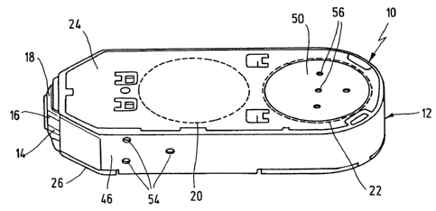
Fig. 1 shows a tape cassette for blood sugar tests in a perspective view;

Fig. 2 shows a metal support for a cover part of the tape cassette in a
perspective
inner view; and

Fig. 3 shows a cover part formed using outsert technique in a view according
to
fig. 2.

The tape cassette 10 shown in the drawing enables a plurality of glucose
analyses to
be carried out locally on blood samples that are collected by the patient
himself. For


CA 02592808 2007-06-22

-5-
this purpose a housing 12 is designed to receive a test tape 14 which is
provided
with a plurality of test fields 16 to which blood can be successively applied
at an
application point 18. The tape is transported by means of two tape reels 20,
22
inserted into the housing 12. The basic sequence of the analysis is derived
for

example from WO 2004/056269 to which reference is herewith explicitly made.
The housing 12 comprises an outsert moulding part 24 designed as a cover part
and
a cassette body 26 that can be connected thereto. The outsert moulding part 24
is
formed using the outsert technique from a metal support 28 according to fig. 2
and
plastic 30 that is moulded thereon according to fig. 3. In this manner it is
possible to

integrate various functional parts 32 onto the prefabricated part in a
technically
advantageous manner for production and application. In the outsert technique,
the
metal support 28 is placed in the hollow tool space of a closable moulding
tool and
preferably enclosed by a hardenable plastic mass by means of injection
moulding. In
this process the plastic is rigidly anchored to the metal support by undercuts
and cut

outs. The process as such is known to a person skilled in the art so that it
is not
necessary to describe further details of the process here.

Fig. 2 shows the metal support 28 that has been shaped as a precut metal sheet
34 by
punching and bending. The precut part 34 has a flat base area 36 from which
various functional parts, in particular spring elements 38, 40 and supporting

elements 42, 44 are bent out.

A leaf spring 38 is provided at a bevelled side face to improve the sealing
function
against the test tape 14 which is guided over a seal that is not shown. In
order to
apply a spring force to the tape spoo122, a spiral spring 40 is located in the
base
area region 36 where the moulded-on end of the spring is deep-drawn in a
circular

shape and the free end of the spring is bent out in a spiral shape towards the
inside
of the housing.


CA 02592808 2007-06-22

-6-
Several angled, laterally undercut supporting hooks 42 are distributed on the
base
area 36 to stabilize the moulded-on anchoring elements. Flaps 44 are provided
as
lateral supporting elements on the edge side of the base area 36.

According to fig. 3 the finished outsert moulding part 24 has side walls 46

supported by the flaps 44 which cover the test tape 14 towards the outside
with the
exception of the area of the application tip 18. Locking hooks 48 made of
plastic are
moulded-on to the supporting hooks 42 for a snap lock with the cassette body
26.
The spiral spring 40 is protected against contact from outside by a cap 50
made of
plastic in the plane of the base area 36. This remains permanently connected
to the

metal support 28 by means of an opposing moulded point 52 on the inside of the
base area 36.

In the injection moulding tool, the leaf spring 38 is pretensioned in the
region of the
adjoining sidewall 46 and is fixed there by centring pins until the solidified
plastic
adopts its holding function due to its shrinking property. The centring pins
form

wall openings 54 in the plastic as seen on the outside of the cap member 24 in
fig. 1.
During final assembly the spring 38 can be pressed out towards the inside into
its
active position by means of a pusher which engages through the openings 54.
Corresponding openings 56 are also present in the area of the cover 50 of the
spiral
spring 40.

It is also basically possible that other parts of the cassette 10 are formed
using the
outsert technology. In particular the cassette body 26 can have a metal
support on
which tape deflectors for the test tape 14 are moulded. These can be kept free
towards the outside after moulding-on the parts of the body that are formed
from
plastic such that the test tape which is guided between the reels 20, 22 over
the tip

18 glides on the metallic tape deflectors with little friction.

Representative Drawing
A single figure which represents the drawing illustrating the invention.
Administrative Status

For a clearer understanding of the status of the application/patent presented on this page, the site Disclaimer , as well as the definitions for Patent , Administrative Status , Maintenance Fee  and Payment History  should be consulted.

Administrative Status

Title Date
Forecasted Issue Date 2010-06-15
(22) Filed 2007-06-22
Examination Requested 2007-06-22
(41) Open to Public Inspection 2007-12-27
(45) Issued 2010-06-15

Abandonment History

There is no abandonment history.

Maintenance Fee

Last Payment of $473.65 was received on 2023-12-18


 Upcoming maintenance fee amounts

Description Date Amount
Next Payment if small entity fee 2025-06-23 $253.00
Next Payment if standard fee 2025-06-23 $624.00

Note : If the full payment has not been received on or before the date indicated, a further fee may be required which may be one of the following

  • the reinstatement fee;
  • the late payment fee; or
  • additional fee to reverse deemed expiry.

Patent fees are adjusted on the 1st of January every year. The amounts above are the current amounts if received by December 31 of the current year.
Please refer to the CIPO Patent Fees web page to see all current fee amounts.

Payment History

Fee Type Anniversary Year Due Date Amount Paid Paid Date
Request for Examination $800.00 2007-06-22
Application Fee $400.00 2007-06-22
Maintenance Fee - Application - New Act 2 2009-06-22 $100.00 2009-05-12
Final Fee $300.00 2010-03-24
Maintenance Fee - Application - New Act 3 2010-06-22 $100.00 2010-05-14
Maintenance Fee - Patent - New Act 4 2011-06-22 $100.00 2011-05-18
Maintenance Fee - Patent - New Act 5 2012-06-22 $200.00 2012-05-24
Maintenance Fee - Patent - New Act 6 2013-06-25 $200.00 2013-05-15
Maintenance Fee - Patent - New Act 7 2014-06-23 $200.00 2014-05-14
Maintenance Fee - Patent - New Act 8 2015-06-22 $200.00 2015-05-19
Maintenance Fee - Patent - New Act 9 2016-06-22 $200.00 2016-05-12
Maintenance Fee - Patent - New Act 10 2017-06-22 $250.00 2017-05-16
Maintenance Fee - Patent - New Act 11 2018-06-22 $250.00 2018-05-10
Maintenance Fee - Patent - New Act 12 2019-06-25 $250.00 2019-05-16
Maintenance Fee - Patent - New Act 13 2020-06-22 $250.00 2020-05-20
Maintenance Fee - Patent - New Act 14 2021-06-22 $255.00 2021-05-14
Maintenance Fee - Patent - New Act 15 2022-06-22 $458.08 2022-05-13
Maintenance Fee - Patent - New Act 16 2023-06-22 $473.65 2023-05-10
Maintenance Fee - Patent - New Act 17 2024-06-24 $473.65 2023-12-18
Owners on Record

Note: Records showing the ownership history in alphabetical order.

Current Owners on Record
F. HOFFMANN-LA ROCHE AG
Past Owners on Record
SACHERER, KLAUS-DIETER
Past Owners that do not appear in the "Owners on Record" listing will appear in other documentation within the application.
Documents

To view selected files, please enter reCAPTCHA code :


To view images, click a link in the Document Description column. To download the documents, select one or more checkboxes in the first column and then click the "Download Selected in PDF format (Zip Archive)" or the "Download Selected as Single PDF" button.

List of published and non-published patent-specific documents on the CPD .

If you have any difficulty accessing content, you can call the Client Service Centre at 1-866-997-1936 or send them an e-mail at CIPO Client Service Centre.


Document
Description 
Date
(yyyy-mm-dd) 
Number of pages   Size of Image (KB) 
Abstract 2007-06-22 1 13
Description 2007-06-22 6 238
Claims 2007-06-22 3 87
Drawings 2007-06-22 1 29
Representative Drawing 2007-11-29 1 9
Cover Page 2007-12-12 1 35
Description 2009-05-27 7 256
Claims 2009-05-27 3 96
Cover Page 2010-05-19 1 36
Correspondence 2010-03-24 2 65
Assignment 2007-06-22 3 111
Prosecution-Amendment 2007-06-22 2 43
Prosecution-Amendment 2008-12-01 2 78
Prosecution-Amendment 2009-05-27 10 378
Correspondence 2010-09-14 2 61