Note: Descriptions are shown in the official language in which they were submitted.
CA 02592937 2007-07-04
BOOT WITH SCRAPER FOR A FERTILIZER OPENER
IN AN AGRICULTURAL MACHINE
Field of the Invention
[0001] The present invention relates to agricultural machines, and, more
particularly,
to fertilizer openers for forming a trench in soil in which fertilizer is
deposited.
Background of the Invention
[0002] An agricultural seeding machine such as a row crop planter or grain
drill places
seeds at a desired depth within a plurality of parallel seed trenches formed
in soil. In
the case of a row crop planter, a plurality of row crop units are typically
ground driven
using wheels, shafts, sprockets, transfer cases, chains and the like. Each row
crop unit
has a frame which is moveably coupled with a tool bar.
[0003] In areas where air seeder type equipment is used to seed small grains
there
has been a significant move to reduce input costs to the seeding process. One
way to
do this is to adopt no-till farming practices to reduce equipment and fuel
costs. Another
way is to combine the operations involved in seeding, for example tillage,
seed bed
preparation, fertilizer and seed placement. A further option is to utilize
combined
operations in a no-till farming practice.
[0004] There are machines presently available that have some ability to
combine
these operations. These are usually divided into two categories, air hoe
drills and air
disc drills. The first utilizes a combination of shanks with shovels or boots
to create a
trench for the seed, basically it 'hoes' a trench. Examples of such tools are
John Deere
1820, Bourgault 5710, Morris Maxim II, 8900 and 9000, or Case ATX Series. The
second type utilizes disc type openers to create the seed trench. Examples of
such
tools are John Deere 1890, Bourgault 5720, Morris Never Pin or Case SDX
Series.
[0005] Not all of these machines are capable of placing fertilizer at the same
time as
seeding. Generally it is easiest to place dry granular fertilizer at the same
time as
17525/JD00081.US
1
CA 02592937 2007-07-04
seeding since that type of fertilizer can be distributed by a similar air
delivery system.
The application of liquid fertilizer requires an additional delivery and
distribution system,
typically not supplied by the air seeder manufacturer. The application of
gaseous
fertilizer such as anhydrous ammonia (also referred to as NH3) also requires
an
additional delivery and distribution system, typically not supplied by the air
seeder
manufacturer. A further difficulty with NH3 is the requirement to effectively
seal the gas
into the ground. This is typically the most challenging task for these
openers.
[0006] To effectively retain the gas in the ground it is necessary to place
the gas
accurately in a trench and seal it therein. To achieve this it is preferable
to create a
small, neat trench at constant depth and close the trench quickly and
efficiently
afterwards. The difficulties encountered with known designs are in all aspects
of this
operation. Those devices suffer from one or more of the following detrimental
actions:
1) too much soil disturbance creating a large trench with soil displaced
significantly; 2)
lack of depth control; and 3) inability to dose or seal the trench immediately
after
release of the gas.
[0007] It is known to use a fertilizer opener with a boot/scraper that is
entirely within
the profile of the opener disc and has no interference with the opposite
trench sidewall
to create a narrow trench. This configuration has experienced difficulties
operating in
adverse conditions since the boot/scraper is not pressed against the opener
disc
sufficiently to prevent soil, mud and/or residue from entering therebetween
and causing
the opener disc to quit turning and push the boot far out thus creating an
excessive
trench. Other known fertilizer openers use boots and scrapers that protrude
significantly from the trench cut by the opener disc, but displace too much
soil from the
trench and make it difficult to close and seal the trench.
[0008] Other types of fertilizer openers allow use of the three main
fertilizer types (dry
granular, liquid and gaseous anhydrous ammonia). However, such openers require
different types of attachments and mounting hardware changes to swap from one
fertilizer type to another. This is labor intensive, with increased costs and
chances of
17525/JDC0081.US
2
CA 02592937 2007-07-04
assembly error.
[0009] What is needed in the art is a fertilizer opener which quickly and
easily allows
for use with dry, liquid and/or gaseous fertilizers.
Summary of the Invention
[0010] The invention comprises, in one form thereof, an agricultural machine,
including
a frame and at least one fertilizer opener carried by the frame for opening a
trench in
soil. Each fertilizer opener includes an opener disc positioned at an angle
relative to a
working direction, a boot positioned behind the opener disc relative to the
working
direction, and at least one fertilizer tube positioned behind the boot
relative to the
working direction. The boot includes a recess at a trailing edge thereof. The
recess at
least partially surrounds at least one fertilizer tube.
[0011] The invention comprises, in another form thereof, a fertilizer opener
for opening
a furrow in soil, including a boot having a trailing edge relative to a
working direction,
and a recess at the trailing edge. The recess is configured for at least
partially
surrounding at least one fertilizer tube.
Brief Description of the Drawings
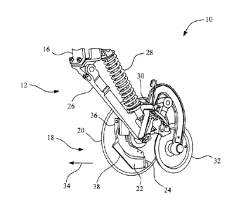
[0012] Fig. 1 is a perspective view of a fertilizer opener assembly, including
an
embodiment of a fertilizer opener of the present invention;
[0013] Fig. 2 is another perspective view of the fertilizer opener assembly
shown in
Fig. 1;
[0014] Fig. 3 is a fragmentary, side view of the fertilizer opener assembly of
Figs. 1
and 2;
[0015] Fig. 4 is a perspective view of the boot/scraper forming part of the
fertilizer
opener of Figs. 1-3;
[0016] Fig. 5 is a top view of the fertilizer opener of Fig. 4; and
[0017] Fig. 6 is a perspective view of the fertilizer opener of Figs. 4 and 5.
17525/JDO0081.US
3
CA 02592937 2012-02-16
Detailed Description of the Invention
[0018] Referring now to the drawings, and more particularly to Figs. 1 and 2,
there is
shown an embodiment of an agricultural machine of the present invention in the
form of
a seeder 10. In the embodiment shown, seeder 10 is in the form of an air
seeder but
may be differently configured.
[0019] Seeder 10 generally includes a plurality of fertilizer opener
assemblies 12, with
each fertilizer opener assembly 12 being substantially identical. Only a
single fertilizer
opener assembly 12 is shown in Figs. 1-3 for simplicity sake. Each fertilizer
opener
assembly 12 is connected to a common tool bar 14, which in turn is coupled to
a
traction unit (not shown), such as an agricultural tractor. For example, tool
bar 14 may
be coupled to an agricultural tractor using a 3-point hitch assembly. Tool bar
14 may be
coupled with transport wheel assemblies, etc. which may be of conventional
design and
not shown for simplicity sake. The transport wheels, in known manner, may
provide
ground drive to supply fertilizer at a selected rate to fertilizer opener
assembly 12
through the use of shafts, chains, sprockets, transfer cases, etc.
[0020] Fertilizer opener assembly 12 includes a frame 16 carrying a fertilizer
opener
18 for opening a trench in the soil in which one or more selected fertilizer
types are
deposited (e.g., dry, liquid and/or gaseous fertilizer). Fertilizer opener 18
is defined as
including an opener disc 20, boot 22 and one or more fertilizer tubes 24.
Frame 16
includes a linkage 26 which is biased in a downward direction with a
compression coil
spring 28. A quick-adjust depth adjuster 30 moves the vertical orientation of
gauge
wheel 31 relative to opener disc 20 to thereby adjust the cutting depth of
opener disc 18
into the soil.
[0021] Opener disc 20 is preferably generally planar, but may also have a
generally
convex or concave shape relative to the working direction 34, depending upon
the
application. It will be appreciated that the side of boot 22 adjacent opener
disc 20 can
be modified accordingly for efficient scraping operation, as will be described
below.
4
CA 02592937 2007-07-04
Opener disc 20 is oriented at an angle of between 4 to 7 degrees relative to
working
direction 34, but may also be at a different orientation.
[0022] Boot 22 includes a mounting bracket 36 providing pivotal coupling with
frame
16. Boot 22 is positioned behind opener disc 20 relative to working direction
34, and
extends slightly past the frontal profile of opener disc 20 to slightly widen
the trench
formed in the soil by opener disc 20. In the embodiment shown, boot 22 has an
interference with the offside trench wall of between approximately 1/8 to
inch,
preferably approximately % inch. This interference ensures that boot 22 is
pressed
against opener disc 20 for effective scraping operation, as will be described
below,
without moving too much soil from the trench.
[0023] More particularly, boot 22 includes a scraper 38 positioned near the
leading
edge of opener disc 20, adjacent the trench side of opener disc 20. Scraper 38
is at the
leading edge of boot 22, and is downwardly angled relative to working
direction 34.
Scraper 38 has a contour closely matching with the trench side of opener disc
20 to
effectively scrape mud, soil and other debris from the trench side of opener
disc 20.
Scraper 38 includes a rearwardly extending beveled edge 40 assisting in
movement of
the mud, soil, etc. away from the leading edge of scraper 38.
[0024] Boot 22 also includes a plurality of mounting features 42 allowing
attachment
with one or more selected fertilizer tubes 24, only one of which is shown in
Figs. 1-3. In
the embodiment shown in Figs. 1-3, mounting features 42 are in the form of a
pair of
mounting holes allowing attachment with one or more fertilizer tubes 24 for
selective
application of dry, liquid and/or gaseous fertilizer. Two mounting holes 42
are provided
so that the fertilizer tube(s) cannot pivot or otherwise move when attached
with boot 22.
Other mounting features of a different number and configuration are possible
for
securing the fertilizer tube(s) to boot 22.
[0025] Boot 22 includes a recess 44 at the trailing edge thereof which at
least partially
surrounds one or more fertilizer tubes 24. This recess 44 protects at least
one of the
fertilizer tubes 24 from becoming dislodged or damaged during operation. More
17525/JDC0081.US
CA 02592937 2007-07-04
particularly, recess 44 has a generally L-shaped configuration surrounding at
least one
fertilizer tube 24 on a leading edge of the fertilizer tube 24 and an opener
disc side of
the fertilizer tube 24. The other side of the fertilizer tube adjacent the
offside wall of the
trench is preferably not covered by the recess so that the selected
fertilizer(s) can be
discharged into the trench and absorbed into the offside and bottom walls of
the trench,
minimizing evaporation into the atmosphere, particularly in the event of a
gaseous
fertilizer.
[0026] A rearward face 46 and rearwardly extending plate 48 define the
generally L-
shaped recess 44. Rearward face 46 has a width which is greater than the width
of
fertilizer tube(s) 24, and rearwardly extending plate 48 has a width less than
the width of
rearward face 46. Plate 48 is positioned between opener disc 20 and fertilizer
tube(s)
24, acting as a thermal barrier therebetween. This is particularly important
when
fertilizer tube 24 is used to apply a gaseous fertilizer which evaporates at -
28 degrees F
when exposed to atmospheric pressure. Plate 48 effectively prevents excessive
cooling
of opener disc 20, which can cause mud and soil to freeze to opener disc 20
and
prevent effective operation of opener disc 20.
[0027] Fertilizer tube 24 includes a bottom discharge opening 50 which is
optionally
oriented at between 30 to 60 degrees from vertical. This beveled side
discharge
opening allows the fertilizer to discharge in a direction away from opener
disc 20. The
fertilizer tube 24 is thus directly exposed to the sidewall of the trench
formed by boot 22.
This is a particular benefit for the application of NH3 fertilizer since it
needs to be rapidly
absorbed by the soil to prevent 'out-gassi ng' (the loss of the gas to the
atmosphere).
[0028] In Figs. 1 and 2, only a single fertilizer tube 24 is shown attached to
boot 22.
The fertilizer tube shown could be a liquid fertilizer tube or gaseous
fertilizer tube, the
primary difference being the diameter of the tube. From the foregoing, it
should also be
apparent that the number and/or type of fertilizer tubes attached to boot 22
can vary.
Moreoever, as shown in Figs. 3-5, a fertilizer tube 24A can also be carried by
frame 16
for depositing fertilizer into the trench prior to closing with closing wheel
32.
17525/JDO0081.US
6
CA 02592937 2007-07-04
$
[0029] During operation, the cutting depth of opener disc 20 is manually set
using
depth adjuster 30. The air seeder 10 is raised at the ends of the field for
turning around,
and lowered for traveling across the field. When the air seeder is lowered,
coil spring
28 biases opener disc 20 into the soil. Opener disc 20 forms a trench in the
soil having
a width corresponding to the projected frontal width of opener disc 20 at an
angle to
working direction 34. The trench is slightly widened using boot 22, and the
lateral force
exerted by the offside side wall against boot 22 biases boot 22 against the
trench side
of opener disc 20 for effective scraping operation. The one or more fertilizer
tubes have
a discharge end which is positioned behind boot 22 at least partially within
recess 44.
The fertilizer is deposited into the trench, which is then covered by dosing
wheel 32.
[0030] Having described the preferred embodiment, it will become apparent that
various modifications can be made without departing from the scope of the
invention as
defined in the accompanying claims.
17525/JDC0081.US
7