Note: Descriptions are shown in the official language in which they were submitted.
CA 02593405 2007-07-05
WO 2006/099378 PCT/US2006/009047
-1-
HVAC SYSTEM WITH POWERED SUBCOOLER
FIELD OF THE INVENTION
[0001] The present invention is directed to an HVAC system. In particular, the
present invention is drawn to a chi.ller system with a powered subcooler.
BACKGROUND OF THE INVENTION
[0002] Extensive development work spanning many decades has been spent in
optimizing the design of commercial air conditioners.
[0003] One attempt to optimize commercial air conditioners includes the
installation
of an economizer. Economizers have been commonly used in screw chillers. A
typical economizer introduces refi-igerant flash gas from an intercooler to
the
compressor at a pressure that is between that of the evaporator and the
condenser.
The introduction of moderate pressure refrigerant gas improves the efficiency
of the
thermodynamic cycle in spite of limited compressor efficiency. In another
attempt to
optimize commercial air conditioners, a heat exchanger is used to cool the
refrigerant
liquid leaving the condenser using refrigerant boiling at an intermediate
pressure
which is returned to the compressor. Both types of systems are commonly used
and
give a relatively small improvement in capacity (about 10% to about 15%) for
typical
air-cooled chiller conditions. Another limitation is that these approaches
require a
special port to the compressor to allow the introduction of intermediate
pressure gas.
Additional compressor losses associated with this port generally do not allow
the full
theoretical benefit of the economizer cycle.
[0004] Powered subcoolers have seen limited use in low-temperature
refrigeration
systems, such as in supermarket refrigerators and/or freezers. They use a
separate
refrigerant circuit for cooling refrigerant liquid in the main refrigeration
system in
order to obtain lower temperatures at the evaporator required for
refrigeration. They
have found little or no use in air conditioning systems. These systems
generally cool
liquid refrigerant to about 32 F to 50 F (0 to 10 C), which would introduce
a
substantial performance penalty in air conditioning systems. In addition, the
prior art
CA 02593405 2007-07-05
WO 2006/099378 PCT/US2006/009047
-2-
teaches the use of separate condensers for the main circuit and subcooler
circuit,
which increases the space requirements for the system.
[0005] With the phase out of HCFC-22 (chlorodifluoromethane), the industry is
moving rapidly toward the use of higher-pressure refrigerants. The new
refrigerants
have pressures higher than that of HCFC-22 with the most promising candidate
being
designated by ASHRAE as R-410A, a mixture of difluoromethane (R32, CH2F2) and
pentafluoroethane (R125, CHF2CF3). This refrigerant has found use in HVAC
chiller
applications. Other higher-pressure refrigerants include carbon dioxide, R32,
and
R125. When the outdoor ambient temperature is very high (i.e., greater than
about
95 F (35 C)), the temperature of refrigerant in the condenser begins to
approach its
critical temperature. For example, R-410A has a critical temperature of about
160 F
(71 C). For carbon dioxide with a critical temperature of 90 F (32.2 C),
the issues
with operation near or above the critical temperature are even greater. As the
refrigerant reaches or exceeds its critical temperature, the condenser loses
the ability
to condense the refrigerant, leading to efficiency and capacity losses and/or
system
failures during times of high outdoor ambient temperature.
[0006] What is needed is an HVAC chiller system having improved cooling
capacity
and efficiency without the drawbacks of the prior art.
SUMMARY OF THE INVENTION
[0007] The present invention includes an HVAC system having a main circuit and
a subcooler circuit. The main circuit includes a main circuit evaporator, a
main circuit
expansion device, a main circuit condenser and a main circuit compressor
connected
in a closed refrigerant loop. The subcooler circuit includes a subcooler
evaporator, a
subcooler expansion device, a subcooler condenser and a subcooler compressor
connected in a closed refrigerant loop. The subcooler evaporator is arranged
and
disposed to exchange heat between liquid refrigerant in the main circuit and
the
refrigerant in the subcooler circuit to cool the liquid refrigerant in the
main circuit
prior to entering the main circuit evaporator. The operation of the subcooler
circuit
provides an increased cooling capacity per unit of a mass flow of cooling
fluid
CA 02593405 2007-07-05
WO 2006/099378 PCT/US2006/009047
-3-
through the main circuit condenser and subcooler condenser for the HVAC system
with a predetermined design efficiency.
[0008] Another embodiment of the present invention includes a refrigeration
system having a main circuit, a first subcooler circuit and a second subcooler
circuit.
The main circuit includes a main circuit evaporator, a main circuit expansion
device, a
main circuit condenser and a main circuit compressor connected in a closed
refrigerant loop. The first subcooler circuit comprising a first subcooler
evaporator, a
first subcooler expansion device, a first subcooler condenser and a first
subcooler
compressor connected in a closed refrigerant loop. The second subcooler
circuit
includes a second subcooler evaporator, a second subcooler expansion device, a
second subcooler condenser and a second subcooler compressor connected in a
closed
refrigerant loop. The first subcooler evaporator and second subcooler
evaporator are
each arranged and disposed to exchange heat between liquid refrigerant in the
main
circuit and the refrigerant in the corresponding subcooler circuit to cool the
liquid
refrigerant in the main circuit prior to entering the main circuit evaporator.
[0009] Another embodiment of the present invention includes an HVAC system
having a main circuit and subcooler circuit. The main circuit includes a main
circuit
evaporator, a main circuit expansion device, a main circuit condenser and a
main
circuit compressor connected in a closed refrigerant loop. The main circuit
circulates
a refrigerant with a critical temperature below about 80 C. The subcooler
circuit
includes a subcooler evaporator, a subcooler expansion device, a subcooler
condenser
and a subcooler compressor connected in a closed refrigerant loop. The
subcooler
evaporator is arranged and disposed to exchange heat between liquid
refrigerant in the
main circuit and the refrigerant in the subcooler circuit to cool the liquid
refrigerant in
the main circuit prior to entering the chiller evaporator. The operation of
the
subcooler circuit provides greater cooling capacity per mass flow of cooling
fluid
through the main circuit condenser and subcooler condenser for the HVAC system
with a predetermined design efficiency.
CA 02593405 2007-07-05
WO 2006/099378 PCT/US2006/009047
-4-
[0010] Another embodiment of the present invention includes a method for
subcooling an HVAC system that includes providing a main circuit comprising a
main
circuit evaporator, a main circuit expansion device, a main circuit condenser
and a
main circuit compressor in a refrigerant loop and a subcooler circuit
comprising a
subcooler evaporator, a subcooler expansion device, a subcooler condenser and
a
subcooler compressor in a refrigerant loop. The method further includes
subcooling
refrigerant in the main circuit with the subcooler evaporator prior to
entering the main
circuit evaporator to provide an increased cooling capacity per unit of
airflow through
the condenser for the HVAC system with a predetermined design efficiency. An
ambient air temperature or a refrigerant temperature is sensed. The compressor
in
each of the main circuit and the subcooler circuit are activated or
deactivated in
response to the sensed condition. The method further includes activating or
deactivating one or more fluid moving devices providing fluid flow to the main
circuit
condenser and subcooler condenser in response to the sensed condition.
[0011] An advantage of the present invention is that the system has a larger
capacity
than is available with conventional economizer cycles, and operates at an
increased
efficiency with respect to conventional economizer cycles.
[0012] A further advantage of the present invention is that the additional
efficiency
and capacity can be provided without complicated equipment or wiring, allowing
the
system to be manufactured at a relatively low cost. The powered subcooler
circuit
includes a design having equipment that is readily available and is easily
manufactured. In addition, the increased cooling capacity of the system of the
present
invention offsets at least a portion of the cost of the additional equipment.
[0013] Yet another advantage of the present system is that the addition of
powered
subcooler systems according to the present invention permits the use of
smaller
condenser coils, while providing increased cooling capacity.
[0014] Another advantage of the present system is that the system may operate
at
high ambient temperatures, including temperatures that exceed 95 F (35 C).
CA 02593405 2007-07-05
WO 2006/099378 PCT/US2006/009047
-5-
[0015] Still another advantage of the present invention is that the system
operates
with a reduced fan noise at the same capacity, as compared to a convention
chiller
system. The reduced fan noise results because the required size of the
condenser and
the number of fans/fan capacity is smaller, therefore reducing the fan noise
produced
by the condenser.
[0016] Still yet another advantage of the present invention is that the system
is able to
provide additional stepped control of subcooler capacity when ambient
conditions
change. Each of the subcooler circuits provides a predetermined amount of
subcooling. Therefore, activating and deactivating the individual subcooling
circuits
in response to subcooling requirements permits the system to operate with less
energy
costs.
[0017] Other features and advantages of the present invention will be apparent
from
the following more detailed description of the preferred embodiment, taken in
conjunction with the accompanying drawings which illustrate, by way of
example, the
principles of the invention.
BRIEF DESCRIPTION OF THE DRAWINGS
[0018] FIG. 1 schematically illustrates a known chiller system.
[0019] FIG. 2 schematically illustrates a chiller system according to one
embodiment
of the present invention.
[0020] FIG. 3 schematically illustrates a chiller system according to an
alternate
embodiment of the present invention.
[0021] FIG. 4 schematically illustrates a chiller system according to another
alternate
embodiment of the present invention.
[0022] FIG. 5 schematically illustrates a chiller system according to still
another
alternate embodiment of the present invention.
CA 02593405 2007-07-05
WO 2006/099378 PCT/US2006/009047
-6-
[0023] FIG. 6 schematically illustrates a chiller system according to still
another
alternate embodiment of the present invention.
[0024] FIG. 7 schematically illustrates a chiller system according to still
another
alternate embodiment of the present invention.
[0025] FIG. 8 schematically illustrates an air conditioning system according
to an
embodiment of the present invention.
[0026] Wherever possible, the same reference numbers will be used throughout
the
drawings to refer to the same or like parts.
DETAILED DESCRIPTION OF THE INVENTION
[0027] FIG. 1 shows a prior art chiller system. This configuration contains a
main
circuit 100 having a first compressor 110, a second compressor, 112, an
expansion
device 126, an evaporator 140, and a condenser 190. The main circuit 100
preferably
uses a higher pressure refrigerant, such as chlorodifluoromethane (CHC1F2),
commonly referred to as ASHRAE designation R-22, or mixtures of
difluoromethane
(CH2F2) and pentafluoroethane (CHF2CF3), commonly referred to as ASHRAE
designation R-410A. The first compressor 110 and second compressor 112 are
preferably scroll compressors. Although scroll compressors are preferred, any
suitable type of compressor may be used. Suitable compressors include, for
example,
screw compressors, reciprocating compressors, rotary compressors, or
centrifugal
compressors. A first check valve 114 and a second check valve 116 are located
between the compressor and condenser to prevent backflow of refrigerant vapor
through the compressor that is not operating when only one is operating.
Although
FIG. 1 depicts two compressors, any number of compressors may be used. A
discharge line 132 supplies pressurized refrigerant vapor to condenser coils
118 and
120. A liquid line 134 takes condensed refrigerant from the condenser coils
118 and
120 to an expansion device 126. The expansion device may be any suitable
expansion device, including, but not limited to, expansion valves, and
capillary tube
arrangements. A mixture of liquid and vapor flows from the expansion device
126
CA 02593405 2007-07-05
WO 2006/099378 PCT/US2006/009047
-7-
through an evaporator inlet 138 and an evaporator 140. Superheated refrigerant
vapor
leaves the evaporator and flows through a suction line 130 back to the first
and second
compressors 110 and 112. A warm fluid 142 enters evaporator 140, commonly
referred to as a chiller, and transfers thermal energy to the refrigerant
fluid to produce
cooled fluid 144. The warm fluid 142 and cooled fluid 144 passing through the
evaporator 140 is preferably a liquid, such as water, ethylene glycol or
brine. The
cooled fluid 144 is preferably used to cool an indoor space. Although warm
fluid 142
and cooled fluid 144 is preferably liquid, the warm fluid 142 and cooled fluid
144
may also be air or other gas. Condenser 190 includes a fan 180 that draws
ambient air
182 through the condenser coils 118 and 120, and exhausts heated air 184 to
the
environment. The system shown in FIG. 1 does not maintain cooling efficiencies
in
high ambient temperatures.
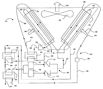
[0028] FIG. 2 shows a chiller system according to a preferred embodiment of
the
present invention including a powered subcooler. FIG. 2 includes the main
circuit
100, as shown in FIG. 1, having the first compressor 110, the first check
valve 114,
the second compressor 112, the second check valve 116, the evaporator 140,
including inlet fluid stream 142 and outlet fluid stream 144, fan 180, ambient
air 182
and heated air 184, arranged substantially as described above with respect to
FIG. 1.
However, the embodiment of the invention shown in FIG. 2 further includes a
first
subcooler circuit 210 and a second subcooler circuit 215. The first subcooler
circuit
210 includes a compressor 250, a condenser coil 260, an expansion device 256
and a
first subcooler 222. The second subcooler circuit 215 includes a compressor
270, a
condenser coil 272, an expansion device 274 and a second subcooler 224. Like
in the
main circuit 100, the expansion device in the first and second subcooler
circuits 210
and 215 may be any suitable expansion device, including, but not limited to,
expansion valves, and capillary tube arrangements. The first and second
subcoolers
222 and 224 each include a heat exchanger that transfers heat between the main
circuit 100 and the first subcooler circuit 210 and the main circuit 100 and
the second
subcooler circuit 215. The heat exchanger of the first and second subcoolers
222 and
224 is preferably a plate heat exchanger, but may be any suitable heat
exchanger. The
liquid line 239 takes condensed refrigerant from the condenser coils 118 and
120 to
CA 02593405 2007-07-05
WO 2006/099378 PCT/US2006/009047
-8-
the second subcooler 224. Liquid refrigerant leaves the outlet of the second
subcooler
224 and then flows into a first subcooler 222. Cooled refrigerant liquid
leaves the
first subcooler 222 through liquid line 236 and flows through an expansion
device 126
to the evaporator 140. The remainder of the main circuit 100 operates as shown
and
described with respect to FIG. 1, above.
[0029] While FIG. 2 shows the main circuit 100 with a single refrigerant
circuit, the
main circuit 100 according to the invention may include systems with multiple
refrigerant circuits. For example, the main circuit may include a scroll
chiller with
design cooling capacities greater than about 30 tons, which typically include
two
circuits. Large scroll or screw chiller systems according to the present
invention may
have as many as four circuits. The evaporator 140 (i.e., chiller) is normally
configured so that each refrigerant circuit is in contact with the full water
flow
through the heat exchanger.
[0030] The first and second subcooler circuits 210 and 215 cool liquid
refrigerant
leaving the condenser coils 118 and 120 in the main circuit 100 by exchanging
heat in
the first and second subcoolers 222 and 224. The exchange of heat provides
subcooling to the liquid refrigerant, permitting the system to operate at a
higher
efficiency, greater capacity and at higher ambient temperatures. The
refrigerant in the
subcooler circuits 210 and 215 are preferably a lower pressure refrigerant,
such as
tetrafluoroethane, commonly known as ASHRAE designation R-134a. Although R-
134a is preferred, refrigerants including R410A, R407C, R-152a, propane,
dimethyl
ether, ammonia or other suitable refrigerant may be used in the first and
second
subcooler circuits 210 and 215.
[0031] The first subcooler circuit 210 comprises a compressor 250, condenser
coil
260, an expansion device 256, and a first subcooler 222 as discussed above.
These
components are connected with refrigerant piping to form a closed loop
refrigerant
circuit. The compressor 250 supplies pressurized refrigerant vapor to
condenser coil
260 via discharge line 252, which cools the refrigerant to form refrigerant
liquid that
flows to the expansion device 256 via liquid line 259. The liquid refrigerant
passes
CA 02593405 2007-07-05
WO 2006/099378 PCT/US2006/009047
-9-
through the expansion device 256 to first subcooler 222, where the refrigerant
evaporates. The evaporating refrigerant in the first subcooler circuit 210
exchanges
heat with the refrigerant in the main circuit 100 in the first subcooler 222.
The
exchange of heat cools the refrigerant in the main circuit 100 to a lower
temperature
prior to the refrigerant in the first subcooler circuit 210 returning to
compressor 250
via suction line 258.
[0032] The second subcooler circuit 215 is similar to the first. A compressor
270 is
connected via a discharge line 262 to a condenser coil 272. Liquid refrigerant
from
the condenser coil 272 then flows through a liquid line 269 to an expansion
device
274 and then through the second subcooler 224. The utilization of multiple
subcoolers permits the use of a simple expansion device as expansion device
274.
However, any suitable expansion device may be utilized. In one embodiment of
the
invention, expansion device 274 is a fixed orifice and expansion device 256 in
the
first subcooler circuit 210 is an expansion valve. Similar to the first
subcooler circuit
210, the refrigerant in the second subcooler circuit 215 evaporates and
exchanges heat
with the refrigerant in the main circuit 100 in the second subcooler 224. The
exchange of heat cools the refrigerant in the main circuit 100 to a lower
temperature.
Suction line 266 allows refrigerant vapor to return from the second subcooler
224 to
the compressor 270 to complete the circuit.
[0033] The condenser 190 of FIG. 2 is arranged and configured to condense
refrigerant vapor in the main circuit 100 and to condense refrigerant in both
the first
and second subcooler circuits 210 and 215. Fan 180 draws ambient air 182
through
the condenser coils 118, 120, 260, and 272 and exhausts heated air 184 to the
environment. The condenser coils 260 and 272 for the first and second
subcooler
circuits 210 and 215 are preferably positioned downstream of the air passing
over
condenser coils 118 and 120 for the main circuit 100. This arrangement allows
the
first and second subcooler circuits 210 and 215 to utilize air leaving the
main
condenser coils without substantially raising the condensing temperature in
the main
circuit 100. The condenser coils 260 and 272 for the first and second
subcooler
circuits 210 and 215 can be separate coils from the condenser coils 118 and
120 of the
CA 02593405 2007-07-05
WO 2006/099378 PCT/US2006/009047
-10-
main circuit 100 or can be a portion of the same coil. In a preferred
embodiment, the
condenser coils 272 and 260 are arranged to provide flow of refrigerant from
the top
of the condenser 190 to the bottom of the condenser 190, in order to provide a
flow
substantially in the direction of gravity. Although flow may be arranged in
either
direction, this embodiment provides an arrangement where the liquid flows more
easily from the condenser 190.
[0034] The heat exchangers for the first and second subcoolers 222 and 224 are
preferably plate heat exchangers. Plate heat exchangers may be provided at a
relatively low cost and small size. Two plate heat exchangers can be assembled
back-
to-back into a single unit, which can save cost and space. Although plate heat
exchangers are preferred, any suitable type of heat exchanger may be used.
Suitable
heat exchangers include tube-in-tube and shell-and-tube heat exchangers.
[0035] The first and second subcoolers 222 and 224 are arranged to provide a
small
pressure drop for the refrigerant liquid when passed through the first and
second
subcoolers 222 and 224 in the main circuit 100 so as to reduce or eliminate
the risk of
undesirable flashing of refrigerant to the vapor phase inside the first and
second
subcooler 222 and 224 heat exchangers. In a preferred embodiment, the heat
exchangers are arranged so that when the first and second subcooler circuits
210 and
215 are not running, the pressure drop is sufficiently small so as to prevent
undesirable flashing of refrigerant to the vapor phase inside the heat
exchangers.
[0036] FIG. 3 shows the same arrangement of the main circuit 100, first
subcooler
circuit 210 and second subcooler circuit 215 shown in FIG. 2. FIG. 3 further
includes
a first bypass valve 310 and a second bypass valve 320. First bypass valve 310
allows
flow of refrigerant liquid around the first subcooler 222. Likewise, second
bypass
valve 320 allows flow of refrigerant liquid around second subcooler 224. In
the
embodiment shown in FIG. 3, free flow of liquid refrigerant around the heat
exchangers is allowed when the one or both of the subcooler circuits are not
operating. The bypass prevents reduction in the pressure drop experienced when
the
refrigerant is passed through one or both of the first and second subcoolers
222 and
CA 02593405 2007-07-05
WO 2006/099378 PCT/US2006/009047
-11-
224. First and second bypass values 310 and 320 are desirable during certain
operating conditions, such those that occur at low ambient temperatures.
[0037] FIG. 4 shows another embodiment of the present invention that includes
the
main circuit 100 and first subcooler circuit 210, as shown and described above
with
respect to FIG. 2. In this embodiment, first subcooler circuit 210 alone is
used to
provide cooling to the refrigerant liquid flowing from condenser coils 118 and
120. A
single subcooler circuit may be used in order to provide the cooling of the
liquid
refrigerant of the main circuit 100 while requiring less components and
piping.
[0038] FIG. 5 shows another embodiment of the present invention having three
subcooler circuits. FIG. 5 shows a configuration of the main circuit 100, the
first
subcooler circuit 210 and the second subcooler circuit 215, as shown and
described in
FIG. 2. However, FIG. 5 also includes a third subcooler circuit 280 that
includes a
third subcooler 282. The third subcooler circuit 280 operates substantially
the same
as the first and second subcooler circuits 210 and 215, including the flow
from a
compressor 284, then to a condenser coil 286, then to an expansion device 288,
then
into the third subcooler 282, and then returning to the compressor 284 to
complete the
cycle. The third subcooler circuit 280 may provide improved coordination of
the
evaporating temperature in the subcooler circuits and the refrigerant liquid
temperature in the main circuit 100. A third subcooler circuit allows for a
greater
portion of the subcooling to be done with a higher evaporating temperature in
the
subcooler circuits, which improves efficiency and capacity of the system.
Additional
subcooling circuits provide a better match between the evaporating
temperatures in
the subcooler circuits and the liquid refrigerant temperature in the main
circuit 100,
which permits increased system efficiency. Although FIG. 2 is shown as
including
two subcooler circuits, FIG. 4 shows one subcooler circuit and FIG. 5 shows
three
subcooler circuits, any number of subcooler circuits may be used. Multiple
subcooler
circuits, including those having two or more, allow greater coordination
between the
liquid temperature in the main circuit 100 and the evaporating temperature of
the
subcoolers, providing improved cycle efficiency.
CA 02593405 2007-07-05
WO 2006/099378 PCT/US2006/009047
-12-
[0039] FIG. 6 shows another embodiment of the invention, including the main
circuit
100, the first subcooler circuit 210 and the second subcooler circuit 215,
substantially
as shown and described in FIG. 2. However, FIG. 6 includes condenser 190
having a
3-row coil for the main circuit 100 upstream in the air from a single coil for
the first
and second subcooler circuits 210 and 215. In this arrangement, the air flows
through
the main circuit 100 coils 118 and 120 before traveling through subcooler
coils 260
and 272. This embodiment provides simple and inexpensive fabrication, where no
reconfiguration of the conventional condenser for the main circuit 100 is
required.
FIG. 6 only requires the addition of the first and second subcoolers 222 and
224 to the
main circuit 100. This embodiment provides a relatively inexpensive
modification
that may be applied to an existing system that only requires minor piping
modifications to the main circuit 100.
[0040] FIG. 7 shows an alternate embodiment of the invention utilizing a
combination
of flash tank and subcooler. In this embodiunent, a flash tank 710 is located
in the
main circuit 100 downstream from the condenser 190 and after passing through
expansion device 720. The flash tank 710 acts to separate the refrigerant
vapor 713
from refrigerant liquid 711, which settles at that bottom of the tank. The
refrigerant in
the first subcooler circuit 210 is evaporated after passing through expansion
device
256. The heat transfer between the evaporating refrigerant in the first
subcooler
circuit 210 and the refrigerant vapor of the main circuit 100 in the flash
tank 710
results in condensing of the refrigerant vapor of the main circuit 100 back to
a liquid
refrigerant 712, which falls to the bottom of the tank, becoming refrigerant
liquid 711.
The liquid refrigerant 711 then travels to expansion device 126 and evaporator
140
via refrigerant liquid line 236. This embodiment has the advantage of
improving heat
transfer coefficient, but it reduces temperature difference and increases
system
complexity.
[0041] FIG. 8 shows an example of the present invention wherein the evaporator
140
of the main circuit 100 is used for an air conditioning application. In this
example,
cool liquid, such as water, ethylene glycol or brine leaves the evaporator 140
via
cooled fluid stream 144. The cool liquid then travels to a heat exchange
device 810 in
CA 02593405 2007-07-05
WO 2006/099378 PCT/US2006/009047
- 13 -
building 820. Heat exchange device 810 may include one or more heat exchangers
disposed within the interior space in order to provide cooling. The cool
liquid
exchanges heat with the heating load within the building 820 and returns to
the
evaporator 140 via warm fluid stream 142. The warm liquid is then cooled in
the
evaporator 140 and the cycle repeats. The use of first and second subcooling
circuits
210 and 215 permits the evaporator to cool a greater amount of fluid, thereby
increasing the amount of heat that may be removed from building 820.
EXAMPLES
[0042] Table 1 below includes the conditions for an air-cooled chiller
according to an
embodiment of the present invention. In this embodiment, the system cools
refrigerant liquid in the main circuit 100 from about 105 F (41 C) to about
60 F (16
C) using two steps. The two steps correspond to the cooling that takes place
in each
of the first and second subcoolers 222 and 224. Refrigerant in the second
subcooler
circuit 215 is evaporated in second subcooler 224. The evaporating refrigerant
in the
second subcooler 224 exchanges heat with the main circuit 100. The heat
exchange
results in a temperature of the liquid refrigerant leaving the second
subcooler 224 of
about 78.5 F (26 C). The evaporating refrigerant in the first subcooler 222
exchanges heat with the main circuit 100. The heat exchange results in a
temperature
of the liquid refrigerant leaving the first subcooler 222 of about 60 F (16
C). The
refrigerant, which has a temperature of about 60 F, is then transported to
the
expansion device 126 and evaporator 140 to cool inlet fluid 142. The first and
second
subcooler circuits 210 and 215 include condenser coils 260 and 272 located in
the air
stream downstream of the condenser for the main circuit 100. The positioning
of the
condenser coils 260 and 272 results in little, if any, change in the
condensing
temperature for the main circuit 100. In this embodiment, the compressor
displacement is the same for both the first and second subcooler circuits 210
and 215.
CA 02593405 2007-07-05
WO 2006/099378 PCT/US2006/009047
-14-
Table 1
Refrigerant Liquid Temperature 105 F
Leaving Condenser
Refrigerant Liquid Temperature 78.5 F
Leaving Second Subcooler
Refrigerant Liquid Temperature 60 F
Leaving First Subcooler
Second Subcooler Evaporating 73.5 F
Temperature
Second Subcooler Condensing 130 F
Temperature
First Subcooler Evaporating 55 F
Temperature
First Subcooler Condensing 125 F
Temperature
Ambient Air Temperature 95 F
Temperature of Air Leaving 115 F
Condenser for Main Circuit
[0043] Table 2 shows the performance for prior art systems compared to systems
provided according to the present invention. The performance data is data
resulting
from performance effects based on computer models that compare compressor
performance curves for commercially available scroll compressors and heat-
exchanger performance calculations. Adding the powered subcooler gives
approximately 25% more cooling capacity and more than 5% efficiency
improvement
at ambient temperatures of 95 F while permitting the main circuit 100 to
operate at
evaporating and condensing temperature that are substantially the same as
known
chiller systems. In addition, the.system provides 35% more cooling capacity
and 10%
more efficiency improvement at ambient temperatures of 115 F. If a larger
evaporator 140 is selected for the main circuit 100 so as to keep the original
evaporating temperature, the system can provide even greater perfonnance
advantages. To maintain the same evaporating temperature, the heat exchange
surface area of the evaporator 140 increases approximately in proportion to
the
increase in cooling capacity. If larger coinpressors are selected for the main
circuit
100 in addition to a larger evaporator 140, then about 40% increase in
capacity is
possible without increasing the physical dimensions of the chiller and while
maintaining the original system efficiency.
CA 02593405 2007-07-05
WO 2006/099378 PCT/US2006/009047
-15-
[0044] For air-cooled chillers, a 2% increase in compressor capacity typically
results
in about a 1% decrease in chiller efficiency if no change is made in the size
of the heat
exchangers. This approximation means that a 7% efficiency improvement from the
powered subcooler would allow roughly an additional 14% in chiller capacity
through
the use of larger compressors while meeting the original efficiency target.
The 40
percent capacity or more increase in capacity (1.14 x 1.27 = 1.45) is possible
by
combining the use of the powered subcooler with larger compressor and
evaporators,
but without any increase in the total condenser air flow rate. Since the
condenser size
normally determines the overall unit dimensions, this increase in capacity
should not
affect the physical size of the unit and while maintaining the same chiller
efficiency.
The ability to increase system capacity for a given physical size and a given
fan
capacity, also helps to reduce overall system cost per unit of cooling
capacity ($/ton).
Table 2
Comparative Comparative Comparative Example 1: Example 2:
Example 1: Example 2: Example 3: Chiller Chiller
Chiller Unit Chiller - No Chiller With with With
With No Subcoolers Economizer Powered Powered
Subcoolers With 4- Subcooler Subcooler
Row Coil and Larger
Evaporator
Evaporating 39.7 39.7 38.7 39.7
Temperature
( F)
Condensing 120.3 118.7 120.3 120.7
Temperature
( F)
Capacity 0.0% 1.0% 11.7% 25.0% 26.8%
Improvement
Based on
Chiller Unit
With No
Subcoolers
Efficiency 0.0% 2.6% 4.7% 5.5% 6.8%
Improvement
Based on
Chiller Unit
With No
Subcoolers
CA 02593405 2007-07-05
WO 2006/099378 PCT/US2006/009047
-16-
[0045] Comparative Example 1 is a chiller system, as shown in FIG.I, including
a
main circuit 100 having a first compressor 110, a second compressor 112, an
expansion device 126, an evaporator 140, and a condenser 190. The condenser
190
includes a three-row coil. The operating conditions for Comparative Example 1
includes an evaporating temperature of about 39.7 F (4.2 C), and a
condensing
temperature of about 120.3 F (49.1 C).
[0046] Comparative Example 2 is a chiller system, as shown in FIG. 1, wherein
the
condenser 190 includes an additional coil than the condenser 190 in
Comparative
Example 1. Comparative Example 2 provides an operating condition that has an
evaporating temperature of about 39.7 F (4.2 C). However, the condensing
temperature is reduced to about 118.7 F (48.2 C). The addition of the fourth
row
coil provides a capacity increase over the Comparative Example 1 of only 1.0%.
Likewise, efficiency is only increased by 2.6% over Comparative Example 1.
[00471 Comparative Example 3 is a chiller system, as shown in FIG. 1, wherein
an
economizer is utilized between the outlet of the condenser 190 and the inlet
of the
evaporator 140. The economizer introduces refrigerant flash gas from an
intercooler
to the compressor at a pressure that is between that of the evaporator 140 and
the
condenser 190. The introduction of intermediate pressure refrigerant gas
allows the
compressor to operate more efficiently. However, the economizer provides a
capacity
increase over the Comparative Example 1 of only 11.7%. Likewise, efficiency is
only
increased by 5.5% over Comparative Example 1. This performance is based on
computer ratings for a known screw chiller with and without an economizer.
[0048] Example 1 is an embodiment of the present invention, as shown in FIG.
2.
The first and second subcoolers 222 and 224 provide subcooling to the
refrigerant in
the main circuit 100 leaving the condenser 190. Example 1 provides an
operating
condition that has an evaporating temperature of about 38.7 F (3.7 C), which
is
below the evaporating temperature of Coinparative Example 1. However, the
condensing temperature is about 120.3 F (49.0 C). The subcooling of the
liquid
CA 02593405 2007-07-05
WO 2006/099378 PCT/US2006/009047
-17-
refrigerant leaving the condenser 190 in the main circuit 100 permits the
increase in
cooling capacity of 25.0% and an efficiency increase of 5.5%. The increase
capacity
and efficiency permit the fabrication of smaller evaporators and/or the
fabrication of
smaller condenser units for the same cooling loads.
[0049] Example 2 is an embodiment of the present invention, as shown in FIG. 2
wherein the system utilizes a larger evaporator than in Example 1. The surface
area
of the evaporator for the main circuit is increased roughly in proportion to
the increase
in cooling capacity so as to maintain approximately the same evaporating
temperature. The increased size corresponds to the increased capacity that is
achieved
by subcooling the refrigerant in the main circuit 100. Example 1 provides an
operating condition that has an evaporating temperature of about 39.7 F (4.3
C).
However, the condensing temperature is about 120.7 F (493 C). The subcooler
with larger cooler permits the increase in cooling capacity of 26.8% and an
efficiency
increase of 6.8%.
[0050] Capacity and Efficiency calculations in Table 2 were based upon the
water
chiller operating at standard conditions (95 F ambient temperature, 44 F
leaving
water temperature).
[0051] In an alternate embodiment, brine may be utilized in the chiller. The
use of
brine results in a lower liquid temperature, which increases the capacity and
efficiency benefit of the powered subcooler system. In addition, a higher
ambient
temperature results in higher capacity and efficiency benefit from the powered
subcooler in the chiller system. The system of the present invention allows
improved
efficiency and capacity at high ambient temperatures. In addition, the system
permits
the use of refrigerants, such as R-410A, R32, R125, and carbon dioxide, which
have
low critical temperatures.
[0052] In the embodiment wherein the refrigerant is carbon dioxide, the
pressure of
refrigerant in the condenser may exceed the critical pressure. In this case,
the
condenser may remove thermal energy from the refrigerant without a change of
phase. The fluid leaving the condenser has properties similar to a liquid in
that the
CA 02593405 2007-07-05
WO 2006/099378 PCT/US2006/009047
- 18-
carbon dioxide expands through a valve to a sufficiently low pressure to
result in a
two-phase mixture. Likewise, the refrigerant entering the condenser acts like
a vapor
in that it will not flash to a two-phase mixture. In this respect, the
condenser performs
essentially the same function as condenser utilizing other lower pressure
refrigerant
and the terms "liquid" and "vapor" can still reasonably apply to the carbon
dioxide
refrigerant at pressures above critical.
[0053] The chiller system having powered subcooler according to an embodiment
of
the invention has the advantage of providing good control over refrigerant
liquid
temperature while using relatively simple controls. For example, lower ambient
air
temperature results in lower refrigerant liquid temperatures in the main
circuit 100
leaving the condenser 190. Likewise, the liquid temperature in the main
circuit 100
leaving the first subcooler 222 to the evaporator 140 is also lower. As the
liquid
temperature of refrigerant in the main circuit 100 approaches the evaporating
temperature, the amount of cooling taking place in the first and second
subcoolers 222
and 224 is greater than optimum for overall system efficiency. In one
embodiment of
the invention, a controller senses a low ambient temperature or a low
refrigerant
temperature in the main circuit 100 exiting the first subcooler 222 and
deactivates one
or both of the first and second subcooler circuits 210 and 215, which allows
the
system to operate at optimum efficiency at off design conditions.
[0054] In addition to maintaining efficiency within the system, turning off
subcoolers
can also provide an additional step of capacity control, which may be
desirable for
better control of fluid temperatures at the chiller and reduced compressor
cycling in
the main circuit 100. For example, a controller can deactivate one or both of
the first
and second subcooling circuits 210 and 215 when a reduced load condition is
detected.
[0055] The compressors 250 and 270 present in the first and second subcooler
circuits
210 and 215 are sized to provide sufficient cooling capacity to the first and
second
subcoolers 222 and 224 to reduce the temperature of the liquid refrigerant
present in
the main circuit 100 to the desired refrigerant temperature. Compressors 250
and 270
CA 02593405 2007-07-05
WO 2006/099378 PCT/US2006/009047
-19-
must be configured to handle high-saturated suction temperatures without
overloading
the compressor motor. In one embodiment of the present invention, compressors
250
and 270 of the first and second subcooler circuits 210 and 215, respectively,
are
configured for compressing high-pressure refrigerant. However, the first and
second
subcooler circuits 210 and 215 are charged with lower-pressure refrigerant.
For
example, compressors 250 and 270 may be configured to compress R-22 or R-407C
refrigerant; however, the first and second subcooler circuits 210 and 215 are
actually
charged with R-134a, a lower-pressure refrigerant. The use of the lower-
pressure
refrigerant in the compressors configured for the higher-pressure refrigerants
allows
the first and second subcooler circuits 210 and 215 to operate more
efficiently at the
higher temperatures and pressures present in the first and second subcoolers
222 and
224. The use of a lower-pressure refrigerant roughly compensates for the
increase in
operating temperatures, which allows the use of conventional air-conditioning
compressors with a minimum of design changes. In addition to R-134a, the
refrigerant present in the first and second subcooler circuits 210 and 215 may
include
R152a, propane, dimethyl ether, ammonia, or other suitable refrigerants.
Suitable
refrigerants may be selected on the basis of lower pressure operation and
environmental and safety concerns.
[0056] Although higher-pressure refrigerants, such as R410A, may be used in
the first
and second subcooler circuits 210 and 215, lower-pressure refrigerants are
preferred
because the compressor would have to be configured to handle the high
operating
pressures associated with high pressure refrigerants. The advantage of using a
lower-
pressure refrigerant in the subcooler circuit is that is offsets the pressure
rise that
would normally occur with the higher evaporating and higher condensing
temperatures found in the subcooler circuit. Thus the operating pressures that
are
similar to those found in the compressor for conventional air conditioning
duty. This
feature prevents overload of the compressor motor or bearings or compressor
shell
with little or no change to the basic design of the compressor.
[0057] In one embodiment of the present invention, the first and second
subcooler
circuits 210 and 215 include compressors 250 and 270 of the same size. In this
CA 02593405 2007-07-05
WO 2006/099378 PCT/US2006/009047
-20-
embodiment, the upstream circuit (i.e., the second subcooler circuit 215) will
have a
larger capacity when both circuits are running since it will see a higher
evaporating
temperature. Equally sized compressors permit operation with either one of the
first
and second subcooler circuits 210 or 215 with substantially equal system
performance.
[0058] In another embodiment of the present invention, the system can use
unequally
sized compressors in the first and second subcooler circuits 210 and 215. The
upstream subcooler circuit (e.g., second subcooler circuit 215) preferably has
a
smaller compressor displacement. This embodiment permits a liquid temperature
change through the two subcoolers that is substantially equal. In addition to
substantially equal liquid refrigerant temperature change, the use of unequal
compressor sizes has the advantage of creating more steps of capacity control.
[0059] From an ideal thermodynamic analysis for optimum system efficiency, the
optimum temperature change for the liquid leaving each subcooler should be
approximately equal to the same value:
4T pt = (TlIq - ETP)/ (Nsub +1)
where: AT pt equals optimum temperature difference per subcooler, Tliq equals
the
refrigerant liquid temperature leaving the main condenser, ETP equals the
evaporating
temperature in the main circuit, and Nsõb equals the number of subcooler
circuits
connected in series.
[0060] For example, for a liquid temperature (Tliq) of 100 F (37.8 C) and an
evaporating temperature (ETP) of 40 F (4.4 C), the total temperature change
is 60
F (15.6 C). For two subcoolers, the optimum temperature change for the liquid
in
the main circuit should be approximately 20 F (-6.7 C) per subcooler. This
calculation results in a temperature difference for each subcooler that
provides
suitable compressor sizing. Optimum compressor sizing requires careful
consideration of the available compressors, system capacity targets, system
cost, and
other factors.
CA 02593405 2007-07-05
WO 2006/099378 PCT/US2006/009047
-21 -
[0061] In still another embodiment, one or both of the first and second
subcooler
circuits 210 and 215 may include multiple compressors or variable-capacity
compressors. The use of multiple compressors and/or variable-capacity
compressors
provides additional capacity control.
[0062] In a preferred embodiment, the condenser arrangement for the first and
second
subcooler circuits 210 and 215 includes condenser coils 260 and 272 positioned
downstream of condenser coils 118 and 120 of the main circuit 100. This
approach
allows for the first and second subcooler circuits 210 and 215 to reject heat
to the
heated air 184 leaving condenser coils 118 and 120 without affecting the
condensing
temperature of the main circuit 100. The difference between the refrigerant
temperature and air temperature is minimized, thereby improving overall system
efficiency. The positioning of the first and second condenser coils 260 and
272
provide additional cooling capacity advantages. The first and second condenser
coils
260 and 272 are preferably arranged and disposed adjacent and downstream in
the air
from condenser coils 118 and 120. In addition, the subcooler circuit condenser
coils
260 and 272 and condenser coils 118 and 120 are preferably arranged
substantially
perpendicular to a flow of air through the condenser 190, as shown in FIG. 2.
The
arrangement of first and second condenser coils 260 and 272 with respect to
condenser coils 118 and 120 provides an increased cooling capacity per unit of
airflow for the chiller system for a given condensing temperature. The
increased
cooling capacity per unit of airflow permits the cooling at the evaporator 140
to take
place using fewer fans or smaller fans, making the system less expensive,
while
maintaining or increasing the cooling capacity over a system that has no first
and
second subcooling circuits 210 and 215.
[0063] In another embodiment of the invention, the condenser 190 includes a
four-
row condenser coil. In this enibodiment, the downstream row (i.e., the fourth
row) is
dedicated to the first and second subcooler circuits 210 and 215 with
substantially no
change to the three-rows in the main condenser coils 118 and 120. This
embodiment
permits the condenser headers for the first and second subcooler circuits 210
and 215
to be located at the opposite end of the condenser coils 260 and 272 to
simplify
CA 02593405 2007-07-05
WO 2006/099378 PCT/US2006/009047
-22-
piping. The flow of the refrigerant through condenser coils 260 and 272 may be
in
either direction through the piping and may be selected based upon piping
considerations or upon efficiency considerations.
[0064] Although the condenser coils 260 and 272 have been shown in FIGS. 2-7
to be
arranged downstream in the air from the main circuit condensers coils 118 and
120,
the invention is not limited to the preferred arrangement, The subcooler
condenser
coils 260 and 272 may also be positioned upstream from the main circuit
condenser
coils 118 and 120. Positioning the condenser coils 260 and 272 upstream in the
air of
the main circuit 100, condenser coils 118 and 120 permits the subcoolers to
receive
cooler ambient air, which allows the subcooler circuit condenser coils 260 and
272 to
condense refrigerant more efficiently. Further, although FIGs. 2-7 are shown
as air-
cooled condensers, otlier fluids, such as water, may be utilized with the
condensers of
the present invention.
[0065] Figure 9 shows an alternate embodiment of the present invention that is
suitable for use in a heat pump in both heating and cooling mode. A powered
subcooler 340 is located in the indoor section of a heat pump. Except for the
powered
subcooler, the heat pump is generally of conventional design. It comprises an
outdoor
coil 312, an indoor coil 322, an accumulator 326 and a compressor 310
connected to
together in a refrigerant circuit. The position of a four-way valve 324
determines
whether the system is in heating or cooling mode.
[0066] In cooling mode, refrigerant vapor flows from the discharge of the
compressor
to the outdoor coil 312 where it condenses to a liquid (shown as direction 305
in FIG.
9). Liquid refrigerant flows through a first check valve 316 around a first
expansion
device 314 and through a liquid line 342 to a second expansion device 318 and
then
into the indoor coil 322, where the refrigerant changes phase to form vapor.
The vapor
returns through the four-way valve 324 and the accumulator 326 to compressor
310.
An outdoor fan 332 and an indoor fan 308 circulate air over the outdoor coil
312 and
the indoor coil 322 respectively.
CA 02593405 2007-07-05
WO 2006/099378 PCT/US2006/009047
-23-
[0067] In heating mode, the four-way valve reverses its position so that
discharge gas
from the compressor 310 flows through the four-way valve 324 to the indoor
coil 322
where it condenses to a liquid (shown as direction 307 in FIG. 9). A second
check
valve 320 allows liquid to bypass the second expansion device 318 and flow to
through the liquid line 342 to the first expansion device 314 located near the
outdoor
coil 312. Two-phase refrigerant then flows from the first expansion device 314
through the outdoor coil 312 where it evaporators into a vapor. The vapor then
flows
through the four-way valve 324 to the accumulator 326 and back to the
compressor
310.
[0068] The powered subcooler is an independent refrigerant circuit comprising
a
compressor 300 that pumps refrigerant to a condenser 306 through an expansion
device 304 to an evaporator 302 and back to the compressor 300. The condenser
306
is located downstream of indoor coil 322 in a duct 330. Although condenser 306
is
shown downstream of the indoor coil 322, the condenser may also be located
upstream from the coil. The evaporator 302 is cools refrigerant liquid in the
main
circuit and is located in liquid line 342.
[0069] In heating mode the powered subcooler provides additional heating and a
higher efficiency than an indoor section and outdoor section that does not
utilize a
powered subcooler 340. The efficiency increase is a result of a cooling of the
refrigerant liquid from the indoor coil 322 while heating air leaving the
indoor coil
322.
[0070] In cooling mode, the powered subcooler 340 provides improved
dehumidification. The operation of the powered subcooler 340 reduces the
temperature of liquid entering the indoor coi1322, which reduces coil
temperature and
increases moisture removal. Subsequent to the passing through the indoor coil
322,
heat is added to the air, which provides reheat. The net effect is a
substantial
improvement in the moisture removal and reduction in the relative humidity of
the
supply air. A humidistat or similar controller can control the operation of
the
CA 02593405 2007-07-05
WO 2006/099378 PCT/US2006/009047
-24-
powered subcooler 340 so that it runs during high humidity conditions and does
not
run during periods of low latent load so as to minimize energy use.
[0071] Figure 10 shows an embodiment of the present invention including a
configuration of check valves that would ensure counterflow in the evaporator
used in
the powered subcooler 340. This configuration would improve performance of the
evaporator 302 while maintaining adequate superheat to the compressor 300 in
the
subcooler. The configuration ensures that refrigerant always flows in the same
direction through evaporator 302 regardless of whether it is heating or
cooling mode.
[0072] Figure 11 shows yet another embodiment that is suitable for use with a
water-
cooled chiller. A compressor 400, a condenser 402, an expansion device 406 and
an
evaporator 408 form a main refrigerant circuit and are connected in a closed
refrigerant loop. Liquid 410 enters the evaporator 408 and exits as chilled
liquid 412.
A subcooler compressor 432, a subcooler condenser 430, a subcooler expansion
device 434, and a subcooler evaporator 404 form a separate refrigerant
circuit. The
subcooler evaporator 404 is located in the liquid line between the condenser
402 and
expansion device 406 in the main refrigerant circuit. Condenser water flows
from a
cooling tower 420 through a pump 422, or other suitable fluid moving device,
through
the condenser 402. A portion of the condenser water flows through the
subcooler
condenser 430. An optional strainer 424 catches dirt and/or debris that could
clog the
subcooler condenser. The subcooler condenser 430 is preferably a brazed plate
heat
exchanger. However, the subcooler condenser 430 may be any suitable
configuration
of heat exchanger capable of operating as a condenser. This configuration can
improve efficiency and capacity of the chiller by providing additional
subcooling.
The lower condensing pressures of this embodiment may allow the use of the
same
refrigerant in the powered subcooler circuit as in the main circuit, which
provided
additional advantages, such as simplified refrigerant charging.
[0073] Other water cooled condenser configurations may be utilized and may be
desirable. For example, the subcooler condenser 430 can be integrated into a
unitary
condenser shell. For in-tube condensation with a shell-and-tube condenser, the
CA 02593405 2007-07-05
WO 2006/099378 PCT/US2006/009047
-25-
subcooler condenser 430 may be separated from the main condenser(s) 402. The
separation may be achieved by use of, for example, a baffle in the head of the
condenser(s). For shell-side condensation, a shell with separate tube sheet
and create
a separate condenser for the powered subcooler in a manner similar to known
two-
circuit condensers. Yet another alternative includes boiling refrigerant
liquid from the
condenser in the main circuit to condense refrigerant in the powered subcooler
and
subsequently recondensing the resulting refrigerant vapor to the main
condenser.
[0074] Many other variations of the invention are possible. For example, while
the
embodiments show a single main refrigerant circuit, multiple circuits are
possible and
would be preferred for large chillers. The main circuits would share a common
cooler
in configurations that are similar to those in the prior art. In addition,
while these
systems for chillers uses cooling liquids such as water or brine, the
evaporator in the
main circuit could cool air or other fluid. This same basic configuration for
the
powered subcooler can also be applied to rooftop air conditioners, residential
air
conditioners with the refrigerant in the main evaporator providing direct
cooling of
indoor air. This system can also be applied to heating systems, in which case
the
condenser would be heating indoor air or hot water and the evaporator would be
drawing thermal energy from outside air, ground loop, or other heat source.
[0075] While the invention has been described with reference to a preferred
embodiment, it will be understood by those skilled in the art that various
changes may
be made and equivalents may be substituted for elements thereof without
departing
from the scope of the invention. In addition, many modifications may be made
to
adapt a particular situation or material to the teachings of the invention
without
departing from the essential scope thereof. Therefore, it is intended that the
invention
not be limited to the particular embodiment disclosed as the best mode
contemplated
for carrying out this invention, but that the invention will include all
embodiments
falling within the scope of the appended claims.