Note: Descriptions are shown in the official language in which they were submitted.
CA 02593435 2013-04-19
NON-COMBUSTIBLE REINFORCED CEMENTITIOUS
LIGHTWEIGHT PANELS AND METAL FRAME SYSTEM FOR A FIRE WALL
AND OTHER FIRE RESISTIVE ASSEMBLIES
FIELD OF THE INVENTION
This invention relates generally to fire wall or other fire resistive
assembly systems comprising metal framing and lightweight structural
cementitious panels, termed here as SCP panels, in residential and
commercial construction. The fire walls or other fire resistive assemblies
may be horizontal (e.g., ceilings) or vertical (e.g. vertical walls). More
particularly, the invention relates to a non-combustible fire wall or other
fire
resistive assembly system, having panels mechanically or adhesively
fastened to steel frame fire wall or other fire resistive assembly systems. If
desired the panels provide a shear resistant diaphragm. The system
provides the following advantageous performance attributes when used with
steel framing: non-combustibility, water durability, mold resistance, high
specific strength and stiffness, economy of building design that results in
speed of assembly, reduced foundation size due to reduced building weight,
and increased ratios of useable building volume for a given building
footprint.
BACKGROUND OF THE INVENTION
A fire wall is a particular class of building construction wall. Section
705 of the 2003 International Building Code,
states in general that each portion of a building separated by
one or more fire walls that comply with the provisions of Section 705 shall be
considered a separate building. The extent and location of such fire walls
shall provide a complete separation. Where a fire wall also separates groups
that are required to be separated by a fire barrier wall, the most restrictive
requirements of each separation shall apply. Fire walls located on lot lines
shall also comply with Section 503.2 of the 2003 International Building Code.
Such fire walls (party walls) shall be constructed without openings. Fire
walls
shall have sufficient structural stability under fire conditions to allow
collapse
of construction on either side without collapse of the wall for the duration
of
1
CA 02593435 2013-04-19
time indicated by the required fire-resistance rating. Typical fire resistance
ratings are 2 hours, 3 hours or 4 hours.
Another class of building wall is termed "fire barriers". Section 706 of
the 2003 International Building Code,
states in general that fire barriers for separation of shafts (also
known as shaft walls), exits, exit passageways, horizontal exits or incidental
use areas, to separate different occupancies, to separate a single occupancy
into different fire areas, or to separate other areas where a fire barrier is
required elsewhere in the 2003 International Building Code or the
International Fire Code, shall comply with Section 706 of the 2003
International Building Code. Typical fire resistance ratings for fire barriers
are 1 hour, 2 hours, 3 hours and 4 hours.
Local building codes and national standard practices require steps be
taken in commercial and residential construction to slow the spread of fire
through attics, crawlspaces, and other interior locations. Thus, where a fire
wall (also known as an area separation wall or party wall) is specified for
commercial or residential construction, materials and constructions are
employed to meet these specifications. Fire walls or other fire resistive
assemblies may be vertical or horizontal. For example, ceilings and
sidewalls of a garage adjacent to the dwelling portion of a residential home
are typically fire walls or fire barriers.
Residential fire walls or other fire resistive assembly systems meet
three structural considerations. First, they form two separate membranes so
that, in a fire, one side can collapse without compromising the entire fire
barrier. Second, the walls typically have details that insure that if the
adjacent
structure collapses in a fire, the fire wall will not collapse. Third, the
walls are
designed for a uniform lateral load of 5 psf to insure lateral stability.
Residential fire walls offer important, specialized construction to
protect occupants from fire in multifamily townhouses and other attached
dwellings. Not only should these assemblies provide rated fire protection,
usually 2 hours, but they must also be designed to be structurally stable
enough to withstand the collapse of an adjacent structure without losing their
integrity as a wall.
2
CA 02593435 2007-07-03
WO 2006/081156
PCT/US2006/002196
Masonry has long been considered an acceptable material for
residential fire walls because of its hardness and perceived strength. An
alternative is comparably fire-rated gypsum drywall assemblies.
In addition to the above-discussed International Building Code, two
principal code bodies that address the area separation-type fire/party walls
are BOCA (See BOCA National Building Code/1990, Section 907Ø) -
Building Officials & Code Administrators International Inc. and SBCCI (See
SBCCI Standard Building Code/1988 Paragraph 403.5.)-Southern Building
Code Congress International. These code bodies identify such assemblies in
their codes as either "fire wall," "party wall" or "townhouse separation wall"
or
"area separation wall". Each has essentially the same structural
requirement:
"Such wall shall be continuous from the foundation to the underside of
the roof sheathing. . . [or shall penetrate through the roof as a parapet]."
(See BOCA National Building Code/1990, Section 907.0) and "Walls shall
have sufficient structural stability under fire conditions to allow collapse
of
construction on either side without collapse of the wall. . ." (See SBCCI
Standard Building Code/1998 Paragraph 403.5).
For additional guidance, a widely accepted reference document is that
of the National Concrete Masonry Assn. (NOMA), TEK 95, "Design Details
for Concrete Masonry Fire Walls."
This document recommends either a double wall or a single wall
laterally supported for stability unless designed as a self-supporting
cantilever. The document further states the wall be designed to withstand a
uniform lateral load of 5 lb./sq. ft. (See NCMA-TEK 95, "Design Details for
Concrete Masonry Fire Walls"). The double wall comprising two separate
fire-rated walls is most frequently used in load-bearing situations since the
fireside portion of the double wall can collapse with the adjoining structure
leaving the opposing fire wall in place.
However, the common masonry fire wall configuration separating
residential wood-frame construction is the single wall in a non-load bearing
mode as a divider between the wood-frame construction on each side.
Lateral support can be provided to stabilize the wall at intermediate floors
3
CA 02593435 2007-07-03
WO 2006/081156
PCT/US2006/002196
=
and roofs but the lateral attachment to the structure is designed so that
collapse of the fire-side structure will not cause the fire wall to fail.
The fire wall is not an impenetrable buttress as many expect, for a 5
lb./sq. ft. lateral design load (the stated recommendation of the NCMA-See
NCMA-TEK 95, "Design Details for Concrete Masonry Fire Walls") is no
different than that of a common interior wall. Also, it is noteworthy to
recognize that the code does not require resistance to collapse of the
adjacent structure into the fire wall but rather that the fire wall remain
standing after collapse.
A common field construction practices is the use of unreinforced
hollow concrete masonry. These masonry fire walls are often cantilevered off
the foundation without any lateral support at intermediate floors or roof. As
a
result they may not meet the required 5 lb./sq. ft. lateral load design when
erected to necessary building heights. For instance, at a design load of 5
lb./sq. ft. the wall height capacity of unreinforced hollow 8-in, concrete
masonry units (CMUs) is about 10.3 ft. (Calculated. Design assumptions:
cantilevered; allowable flexural tensile stress 23 lb./sq. in., increased one-
third for wind; 100 lb./cu. ft. hollow block, Section Modules S=81 (8-in. CMU)
and 160 (12-in. CMU) per NCMA-TEK 2A, "Sizes and Shapes of Concrete
Masonry Units") when free standing as a cantilever and 18.0 ft. (See NCMA-
TEK 63, "Partially Reinforced Concrete Masonry Walls") when simply
supported at roof or intermediate floor. If 12-in. CMUs are used, the heights
increase to only 14.7 ft. (Calculated. Design assumptions: cantilevered;
allowable flexural tensile stress 23 lb./sq. in., increased one-third for
wind;
100 lb./cu. ft. hollow block, Section Modules S=81 (8-in. CMU) and 160 (12-
in. CMU) per NCMA-TEK 2A, "Sizes and Shapes of Concrete Masonry
Units") and 25.4 ft. (See NCMA-TEK 95, "Design Details for Concrete
Masonry Fire Walls") respectively. See Maurice J. Marchello, Gypsum Fire
Wall's Efficiency Gives it Performance Edge, Form and Function, Issue 3
(1990) (also available at
http://www.usg.com/Design_Solutions/2_2_8_separationwall.asp).
A masonry cavity fire wall is described in Technical Notes 21, Brick
Masonry Cavity Walls, Technical Notes on Brick Construction, Brick Industry
4
CA 02593435 2007-07-03
WO 2006/081156 PCT/US2006/002196
Association, Reston, Virginia (August 1998). Fig. 1 shows an embodiment of
such a cavity wall 1. Brick masonry cavity walls have two wythes of masonry
separated by an air space connected by corrosion-resistant metal ties. The
exterior masonry wythe 4 can be solid or hollow brick, while the interior
masonry wythe 2 (shown as cinderblock) can be solid brick, hollow brick,
structural clay tile, or hollow or solid concrete masonry units. The selection
for each wythe depends on the required wall properties and features. A
cavity of a spacing SS of 2 to 4 1/2 in. (50 to 114 mm) between the two
wythes 2, 4 may be either insulated (rigid board insulation 3 shown) or left
as
an air space. A clearance of a minimum distance S of 1 inch (2.5 mm) is
provided between the rigid board insulation 3 and outer wythe 4. The interior
surface of the cavity wall 1 may be left exposed or finished in conventional
ways. The outer wythe 4 may be provided with weep holes 6. Flashing 7
may also be provided.
Some parts of the country use the term "reinforced cavity walls" to
denote a multi-wythe masonry wall with grout placed between the wythes.
This should actually be considered a multi-wythe grouted masonry wall.
Since the definition of a cavity wall includes an air space, this type of wall
is
not truly a cavity wall.
Fire resistance ratings of brick masonry cavity walls range from 2 to 4
hours, depending upon the wall thickness and other factors. Due to their
high fire resistance properties, brick walls are useful as fire walls or
building
separation walls for compartmentation in buildings. By using
compartmentation, the spread of fire can be halted. Technical Notes 16, Fire
Resistance Cavity Walls, Technical Notes on Brick Construction, Brick
Industry Association, Reston, Virginia (April 2002) describes fire ratings and
applicable design conditions.
Some important ASTM standards to understand are ASTM E-119 and
C-36. ASTM E 119, Test Methods for Fire Tests of Building Construction and
Materials, is the test standard that provides the hourly resistance ratings
for
wall, floors, roofs, beams, and columns based on adherence of fire exposure
to a time-temperature curve. ASTM E-119 is a fire testing method in which an
assembly must resist the fire exposure described for the desired
5
CA 02593435 2007-07-03
WO 2006/081156 PCT/US2006/002196
classification time without passage of flame or gases hot enough to ignite
cotton waste on the non-fire side. The method also entails a specific
temperature rise during the test and a second partition specimen that must
resist the effects of a hose stream after a fire test of one-half the time
duration of the first test. Under E-119, wall and partitions having a fire
rating
of one hour or more must also be subjected to a hose streantest. The hose
stream test has nothing to do with fire fighting practices or strategies. It
is
actually a convenient way to measure an assembly's ability to withstand
lateral impact from falling debris during the fire endurance period and before
active fire suppression efforts begin.
ASTM C-36 defines the standards for gypsum board (the product
rather than a system containing gypsum board). The C-36 standard entails a
variety of product standards that the product must be tested to meet,
including composition of various types of gypsum board, flexural strength,
humidified deflection, hardness, nail-pull resistance and dimensions.
Although the only fire-related characteristics regular core gypsum board must
have in ASTM C-36 are a noncombustible core and a maximum flame spread
classification of 25, type "X" board, referred to as "special fire-resistant,"
must
meet specific fire-resistance standards.
To meet the ASTM C-36 standard for 1/2-in. type 'X' board, an
assembly using the 1/2-in. type 'X' board on both sides of a load-bearing
wood-stud wall must withstand an ASTM E-119 method fire test for 45
minutes. To meet the standard for 5/8-in. type "X" board, a similar assembly
with 5/8-in. type "X" board must withstand a similar fire test for 1 hour.
Fire walls may be load bearing or non-load bearing. Unless otherwise
noted, a load bearing wall is tested with a constant superimposed load
applied to the specimen throughout the fire test to simulate 78% or more of
the maximum allowable design load per the Fire Resistance Design Manual -
Gypsum Systems, 17th edition, p. 8 Gypsum Association (2003).
An alternative way of determining the fire resistance of a cavity wall
assembly is by using the calculated fire resistance method. This approach is
approved by the model building codes for determining fire ratings of walls
that are not physically tested by ASTM E 119 Test Methods for Fire Tests of
6
CA 02593435 2007-07-03
WO 2006/081156 PCT/US2006/002196
Building Construction and Materials. The fire rating of cavity walls can be
calculated using Technical Notes 16B, Calculated Fire Resistance, Technical
Notes on Brick Construction, Brick Industry Association, Reston, Virginia
[June 1991] (Reissued Aug. 1991)
Masonry walls, while having good fire resistance, are heavy. An
alternative to masonry construction is to construct fire walls by fastening
flat
modular units from wood or metal trusses or stud walls.
US Patent No. 6,226,946 to Stough et al. discloses the modular units,
typically fire-rated gypsum board, are abutted edge to edge, and provide a
barrier to flame and fire-fighting water. Typically gaps or seams between
individual modules are covered to reduce the rate of flame and water
penetration through the fire wall.
Two different area separation systems employing gypsum board are
cavity-type USG Area Separation and solid-type USG Area Separation Walls.
Cavity-type area separation walls are used as commonly shared party
walls and fire barriers with non-load-bearing framing. They consist of USG
Steel C-H Studs and 1-in. SHEETROCK Brand Gypsum Liner Panels set in
USG Steel C-Runners and faced both sides with 1/2-in. SHEETROCK
Brand Gypsum Panels, F1RECODE C Core.
The solid system is built with two 1-in. SHEETROCK Brand Gypsum
Liner Panels installed vertically between 2-in. steel H-studs and C-runners.
For sound attenuation and added fire protection, THERMAFIBER SAFB
insulation can be added to both area separation wall systems.
Both systems function the same way. The fire resistant gypsum panels
provide 2-hr. fire-rated performance (3-hr. rated USG Area Separation Walls
systems are also available). The steel studs holding the gypsum panels are
attached to the unit's wood framing using aluminum angle clips. When
exposed to fire, these "break away" clips melt and break on the exposed
side, allowing the burning wood frame to fall away. The fire barrier remains
intact to protect adjacent units.
Break away fasteners, for example break away clips, are fasteners
which attach fire walls (or fire barriers) to adjacent structures so that, in
the
event of a fire in the adjacent structure, the adjacent structure can fall
away
7
CA 02593435 2007-07-03
WO 2006/081156 PCT/US2006/002196
from the fire wall while the fire wall maintains its structural integrity
throughout the fire.
Likewise, commercial construction employs fire walls. For example, a
basic system has 25-ga., 2-1/2-in, deep USG Steel C-H Studs, 1-in.
SHEETROCK Brand Gypsum Liner Panels (which engage the flanges of the
C-H studs) and two layers of 1/2-in. SHEETROCK Brand Gypsum Panels,
FIRECODE C Core. IMPERIAL FIRECODE C Gypsum Panels can be used
in place of the SHEETROCK Brand Panels if a veneer plaster finish is
desired. The assembly of the system with the stud-flanges engaging the shaft
wall liner panels is progressive and permits the entire assembly to be
installed from the floor side of the shaft. This basic system is UL classified
(UL Designs U 438, U459, U467, U469). The USG Cavity Shaft Walls are
covered by all three model building codes (BOCA, ICB0 and SBCCI) under
National Evaluation Report NER-258. The system has been designed and
tested using accepted engineering practices with deflection criteria of L/120,
L/240 and L/360 clear partition heights. Additionally, limiting height tables
for
the system account for flexural and shear forces. Variations of the system
have been fire tested up to 4 hours, including four UL design listings up to 2
hrs. Over the years the system has evolved. An original shaft wall system
employed a solid gypsum wall using a steel H-stud. The next generation had
a cavity created by using a steel box "T" stud. The next generation system
uses a steel C-H stud that is lighter in weight and permits less heat and
sound transmission than the previous type stud did.
US Patent No. 6,694,695 to Collins et al. discloses that, while wooden
studs are formed of solid wood, typically having nominal cross section
dimensions of two inches by four inches, the much greater structural strength
of metal, such as twenty-gauge galvanized steel allows building studs to be
employed which are not solid, but rather are hollow and have a channel or
"C-shaped" cross section. To conform to the architectural plans and building
materials developed over the years based on the use of wooden studs
having specific cross sectional dimensions, commercially available metal
studs are constructed with the same outer dimensions in which wooden studs
have been manufactured for many years. Specifically, metal studs are
8
CA 02593435 2007-07-03
WO 2006/081156
PCT/US2006/002196
typically formed of sheet metal bent to encompass a cross sectional area
having nominal dimensions of two inches by four inches.
For ease of fabrication the metal studs are formed of sheet metal bent
into a generally "U-shaped" cross section and in which a relatively broad
central web is flanked by a pair of narrower sides that are bent at right
angles
to the web or base. The web typically has a uniform nominal width of either
four inches or three and one half inches, and the sides of the U-shaped stud
typically extend a nominal distance of two inches from the web. To enhance
structural rigidity the edges of the sides of the metal stud are normally bent
over into a plane parallel to and spaced from the plane of the web. These
turned over edges of the side walls thereby form marginal lips which are
typically one quarter to one half an inch in width. The finished stud
therefore
has a generally "C-shaped" cross section.
The overhead beams that extend along the tops of the studs in interior
building wall construction have a U-shaped configuration. They are each
formed with a horizontally disposed web from which a pair of side walls
depend vertically on opposite sides of the web. The side walls embrace the
sides of the vertical studs so that the upper extremities of the studs extend
perpendicular into the concave, downwardly facing channel formed by the
overhead beam. The spacing of the studs along the length of the beam is
typically either sixteen or twenty-four inches.
One type of fire wall for commercial structures is known as an area
separation fire wall/party wall system. USG Area Separation Fire Walls/Party
Walls are used for constructing common walls with fire-resistive protection
for
adjacent properties. These lightweight, non-load-bearing gypsum drywall
assemblies are designed as vertical fire barriers for fire walls and party
walls
separating occupancies in wood-frame apartments and townhouses. Large-
size gypsum panels used in conjunction with steel studs and runners quickly
become thin, space-saving walls offering excellent privacy.
Available in two basic systems both providing fire-resistant walls from
ground level to roof:
Solid Type, with independently framed interior gypsum panel surfaces
both sides of fire wall or party wall. Cavity Type, with integral interior
gypsum
9
CA 02593435 2007-07-03
WO 2006/081156 PCT/US2006/002196
panel surfaces for commonly shared party walls between apartments. Solid-
Type wall has two 1" thick SHEETROCK Brand Gypsum Liner Panels
installed vertically between 2" USG Steel C-Runners. Panel edges are
inserted in 2" USG Steel H-Studs spaced 24" on center C-runners are
installed at top and bottom of wall and back-to-back between vertical panels
at a convenient height above each intermediate floor. H-Studs are attached
on both sides to adjacent wood framing at intermediate floors, the bottom
chords of attic trusses, and at the roof line with 0.063" USG aluminum angle
clips designed to break away when exposed to fire, thus permitting a fire-
damaged structure to fall while the fire barrier remains intact. These USG
aluminum break away clips are screw attached to studs and framing.
With aluminum angle clips attached on both sides of 25 gauge H-
studs, the assemblies are suitable for spans (between clip angle supports) up
to 10' under 5 psf lateral load without exceeding L/240 allowable deflection
(for walls with exterior exposure, see section 3.4 of the specification).
With 2" THERMAFIBER Sound Attenuation Fire Blankets (SAFB)
stapled each side of liner panels, the assembly has obtained a 3 hr. fire
resistance rating allowing separate selection and construction of tenant
walls.
Cavity-Type Wall consists of steel C-H Studs and SHEETROCK Brand
Gypsum Liner Panels set in steel runners and faced both sides with
SHEETROCK Brand Gypsum Panels, Water-Resistant, F1RECODE C Core.
Liner panels, 1" thick, are erected vertically with ends set into 2-1/2" USG C-
Runners and edges inserted into specially formed 2-1/2" USG Steel C-H
Studs. C-runners are installed singly at top and bottom of wall and back-to-
back between vertical liner panels on a line above each intermediate floor,
the bottom chords of attic trusses, and at roof line. Aluminum clips, which
attach the C-H Studs on both sides to adjacent wood framing, break away in
the same fashion as with solid-type walls. To improve sound transmission
loss, THERMAFIBER SAFB are inserted in the stud cavity and RC-1
Resilient Channels or equivalent may be used to isolate the face layer on the
cavity side.
With aluminum angle clips attached on both sides of 212CH25 steel
studs, the assemblies are suitable for spans (between clip angle supports) up
CA 02593435 2013-04-19
to 10' under 5 psf lateral load without exceeding L/240 allowable deflection
(for walls with exterior exposure see section 3.4 of the specification).
Components used in these systems are designed to permit temporary
exposure to inclement weather during construction. These systems may be
used in buildings up to four stories high (44 feet) and with all common floor-
ceiling heights found in multi-family housing.
Current USG Area separation wall systems are described in USG
publication SA925 09250, Fire Wail/Party Wall area separation wall systems.
Additional information is provided in US Patent Nos. 7,849,650 and 8,122,679.
Another important type of fire resistive structure is a shaft wall. Shaft
walls are wall that enclose elevator shafts and other vertical shafts in a
building. Should a fire occur, firefighters control the use of elevators while
the stairwells provide the only means for occupant egress or rescue within a
building. These walls must have the strength to withstand lateral loads and
provide fire protection. A current shaft wall system is the USG SHEETROCK
brand Cavity Shaft wall system. It provides up to 4-hour fire resistance and
sound ratings up to 52 STC. It resists intermittent lateral loads and fatigue
under cyclic lateral loading which is caused by elevators moving in the shaft.
The assemblies are constructed of SHEETROCK brand gypsum liner panels
friction fitted into USG SHEETROCK brand C-H studs in a progressive
manner with SHEETROCK brand gypsum panels applied to the face. Typical
shaft walls in a building include elevator shafts, stairwells, mechanical
shafts
(HVAC, plumbing, electrical, etc.), horizontal membranes or metal duct
enclosures, and air return shafts (unlines).
Additional information on current USG shaft wall systems is provided
by USG publication SA926 09250 Shaft Wall Systems.
Additional information is also provided in US Patent Nos. 7,849,650 and
8.122,679.
US Patent No. 6,620,487 to Tonyan et al.,
discloses a reinforced, lightweight, dimensionally
stable structural cement panel (SCP) capable of resisting shear loads when
fastened to framing equal to or exceeding shear loads provided by plywood
11
CA 02593435 2013-04-19
or oriented strand board panels. The panels employ a core of a continuous
phase resulting from the curing of an aqueous mixture of calcium sulfate
alpha hemihydrate, hydraulic cement, an active pozzolan and lime, the
continuous phase being reinforced with alkali-resistant glass fibers and
containing ceramic microspheres, or a blend of ceramic and polymer
microspheres, or being formed from an aqueous mixture having a weight
ratio of water-to-reactive powder of 0.6/1 to 0.7/1 or a combination thereof.
At least one outer surface of the panels may include a cured continuous
phase reinforced with glass fibers and containing sufficient polymer spheres
to improve nailability or made with a water-to-reactive powders ratio to
provide an effect similar to polymer spheres, or a combination thereof.
However, US Patent No. 6,620,487 contains no teaching to specifically
employ these shear panels in a fire wall system.
US Patent No. 6,241,815 to Bonen,
also discloses formulations usRfill for SCP !panels.
US Patent No. 7,455,738
discloses a multi-layer process for producing structural
cementitious panels (SCP7s or SCP panels), and SCP's produced by such a
process. After one of an initial deposition of loosely distributed, chopped
fibers or a layer of slurry upon a moving web, fibers are deposited upon the
slurry layer. An embedment device mixes the recently deposited fibers into
the slurry, after which additional layers of slurry, then chopped fibers are
added, followed by more embedment. The process is repeated for each
layer of the board, as desired.
There is a need for an improved economical, easy to assemble,
durable and non-combustible total fire wall system.
SUMMARY OF THE INVENTION
The present invention relates to a fire wall or other fire resistive
assembly system (fire barriers) for residential and light commercial
construction including a metal frame and lightweight structural cementitious
panel (SCP). This lightweight SCP panel is made from a mixture of inorganic
binder and lightweight fillers. The present inventors have discovered that
replacing typical fire-rated gypsum board with this selected SCP panel results
12
CA 02593435 2007-07-03
WO 2006/081156 PCT/US2006/002196
in fire walls of increased strength and resistance to shear. This, for
example,
results in a fire wall better able to withstand forces exerted by water from a
fire hose. The fire wall systems of the present invention are also suitable to
make load bearing fire walls. Typical fire resistance ratings for fire walls
are 2
hours, 3 hours and 4 hours. Typical fire resistance ratings for fire barriers
are
1 hour, 2 hours, 3 hours and 4 hours.
In particular the present invention relates to SCP panels,
mechanically and/or adhesively fastened to a fire wall or other fire resistive
assembly light gauge cold formed metal framing system, which acts as a
shear resistant diaphragm. Selecting a combination of a metal frame with
SCP panels achieves a synergy of a completely non-combustible fire wall
having shear resistance and water durability. By a fully non-combustible
shear diaphragm on light gauge cold rolled (cold formed) metal frame is
meant a system in which all elements pass ASTM E-136. For example, the
fire wall system may include SCP panels employed with a metal framing
system employing any standard light-gauge steel C-channels, U-channels, 1-
beams, square tubing, and light-gauge prefabricated building sections.
As the thickness of the board affects its physical and mechanical
properties, e.g., weight, load carrying capacity, racking strength and the
like,
the desired properties vary according to the thickness of the board. Thus, the
desired properties which a shear rated panel with a nominal thickness of 0.5
inches (12.7 mm) should meet include the following.
The SCP panel when tested according to ASTM 661 and American
Plywood Association (APA) Test Method S-1 over a span of 16 inches (406.4
mm) on centers, should have an ultimate load capacity greater than 550 lbs
(250 kg) under static loading, an ultimate load capacity greater than 400 lbs
(182 kg) under impact loading and a deflection of less than 0.078 inches
(1.98 mm) under both static and impact loading with a 200 lb (90.9 kg) load.
For use in fire wall or other fire resistive assembly system construction
that also provide shear walls, SCP panels should meet building code
standards for shear resistance, load capacity, water-induced expansion and
resistance to combustion, as measured by recognized tests, such as ASTM
E72, ASTM 661, and ASTM C 1185 or equivalent, as applied to structural
13
CA 02593435 2007-07-03
WO 2006/081156 PCT/US2006/002196
plywood sheets. SCP panels are also tested under ASTM E-136 for non-
combustibility ¨ plywood does not meet this test.
The nominal racking shear strength of a 0.5 inch (12.7 mm) thick
panel measured by the ASTM E72 test using the nail size and spacing
described above should be at least 200 lbs/ft ( about 300 kg/m), typically at
least 720 lbs/ft (1072 kg/m).
A 4 x 8 ft, 1/2 inch thick panel (1.22 x 2.4 m, 12.7 mm thick) should
weigh no more than 104 lbs (47 kg) and preferably no more than about 96 or
85 lbs (about 44 or 39 kg).
The panel should be capable of being cut with the circular saws used
to cut wood.
The panel should be capable of being fastened to framing with nails or
screws.
The panel should be machinable so that tongue and groove edges can
be produced in the panel.
The panel should be dimensionally stable when exposed to water, i.e.,
it should expand as little as possible, preferably less than 0.1% as measured
by ASTM C 1185.
The panel should not be biodegradable or subject to attack by insects
or rot.
The panel should provide a bondable substrate for exterior finish
systems.
The panel should be non-combustible as determined by ASTM El 36.
After curing for 28 days, the flexural strength of a 0.75 inch (19. mm)
thick SCP panel having a dry density of 65 lb/ft3 (1041 kg/m3) to 90 lb/ft3
(1442 kg/m3) or 65 lb/ft3 (1041 kg/m3) to 95 lb/ft3 (1522 kg/m3) after being
soaked in water for 48 hours should be at least 1000 psi (7 MPa), e.g. at
least 1300 psi (9 MPa) preferably at least 1650 psi (11.4 MPa), more
preferably at least 1700 psi (11.7 MPa), as measured by ASTM C 947. The
panel should retain at least 75% of its dry strength.
When used for walls, the nominal racking shear strength of a 0.5 inch
(12.7 mm) thick panel measured by the ASTM E72 test using the appropriate
14
CA 02593435 2007-07-03
WO 2006/081156 PCT/US2006/002196
metal studs, fastener, stud spacing and fastener spacing typically is at least
720 lbs per lineal foot (1072 kg per lineal meter).
The present SCP vertical wall diaphragm may have a higher specific
racking shear strength and stiffness than a shear wall system of load bearing
masonry. Specific racking shear strength is defined as the unit weight of a
shear wall system in lbs/sq. ft. to satisfy a particular racking shear
requirement (in lbs/linear foot).
For a given nominal wall racking shear strength specification, in the
range between 200 ¨ 1200 plf for a given wall thickness, the specific nominal
wall racking shear strength of an SCP sheathed shear wall will be greater
than a masonry shear wall of the same nominal thickness that meets the
same racking shear requirement. For example, for a shear wall with a
nominal thickness of 4", an SCP/steel frame shear wall will weigh
approximately 4 psf. A 4" nominal thickness masonry wall (using lightweight
CMU) will weigh approximately 30 psf. As a result, for a 4" wall with a
nominal racking shear strength requirement of 700 plf, the specific wall
racking strength of the SCP is 175p1f/psf, the specific wall racking strength
of
the CMU wall is 23.3 plf/psf. The specific wall racking strength advantage of
the SCP wall versus CMU is true over the full range of racking strengths
considered (200-1200 plf nominal) and for wall thicknesses of 4" to 12".
The present system having a vertical shear diaphragm on light gauge
cold rolled metal frame also is typically water durable. Preferably the
vertical shear diaphragm load carrying capacity of a system of the present
invention will not be lessened by more than 25% (more preferably will not
be lessened by more than 20%) when exposed to water in a test wherein a
2 inch head of water is maintained over a horizontally oriented diaphragm of
3/4 inch thick SCP panels fastened on a 10 foot by 20 foot metal frame for a
period of 24 hours. In this test, the 2 inch head is maintained by checking,
and replenishing water, at 15 minute intervals. Then the system is
reoriented vertically and the vertical shear diaphragm load carrying capacity
of the system is measured.
Preferably the system of the present invention will not absorb more
than 0.7 pounds per square foot of water when exposed to water in a test
CA 02593435 2007-07-03
WO 2006/081156 PCT/US2006/002196
wherein a 2 inch head of water is maintained over 3/4 inch thick SCP
panels fastened on a 10 foot by 20 foot metal frame for a period of 24
hours. In this test, the 2 inch head is maintained by checking, and
replenishing water, at 15 minute intervals.
Also, combining non-combustible SCP panels with metal framing
results in an entire system that resists swelling due to moisture. Preferably
in the system of the present invention a 10 foot wide by 20 foot long by 3/4
inch thick diaphragm of the SCP panels attached to a 10 foot by 20 foot
metal frame will not swell more than 5% when exposed to a 2 inch head of
water maintained over the SCP panels fastened on the metal frame for a
period of 24 hours. In this test, the 2 inch head is maintained by checking,
and replenishing water, at 15 minute intervals.
Also, the present fire wall or other fire resistive assembly system of a
diaphragm of SCP panel on metal frame leads to a mold and mildew
resistant fire wall or other fire resistive assembly system. Preferably every
component of the system of the present invention meets ASTM G-21 in
which the system achieves approximately a rating of 1 and meets ASTM D-
3273 in which the system achieves approximately a rating of 10. Preferably
the system of the present invention supports substantially zero bacteria
growth when clean.
Another preferred attribute of the present fire wall or other fire resistive
.
assembly system of a diaphragm of SCP panel on metal frame is that
preferably it is inedible to termites.
A potential advantage of the present system is that, due to its being
lightweight and strong, the present fire wall or other fire resistive assembly
system of a vertical diaphragm of 3/4 inch thick SCP panel (or 1/2 inch thick
SCP panel) on metal frame reduces foundation size due to reduced building
weight. The lightweight nature of this system typically avoids the dead load
associated with masonry systems. Less dead load also allows building
comparable size structures on less stable soil possessing relatively low
bearing capacities.
Building codes and design standards contain minimum thickness
requirements for masonry shear walls. The minimum nominal thickness for
16
CA 02593435 2007-07-03
WO 2006/081156 PCT/US2006/002196
masonry (CMU) shear walls in a one story building is 6 inches. The minimum
thickness of masonry shear walls (CM U) for buildings more than 1 story is 8
inches. SCP with steel framing shear walls do not have a similar minimum
requirement, and can be designed per established engineering principles at
thicknesses of less than 8 inches for multi-story buildings, and at
thicknesses
of less than 6 inches for single story buildings. Using a 6 inch thick
SCP/steel frame shear wall to replace an 8 inch thick masonry shear wall can
result in a significant increase in useable building volume.
Typical compositions for embodiments of panels of the present
invention which achieve the combination of low density, improved flexural
strength, and nailability/cuttability comprise inorganic binder (examples -
gypsum-cement, Portland cement or other hydraulic cements) having,
distributed throughout the full thickness of the panel, selected glass fibers,
-
lightweight fillers (examples - hollow glass microspheres, hollow ceramic
microspheres and/or perlite uniformly), and superplasticizer/high-range water
reducing admixtures (examples - polynapthalene sulfonates, poly acrylates,
etc.).
The system of the present invention may employ single layer or multi-
layer SCP panels. In the multi-layer SCP panel the layers may be the same
or different. For example, the SCP panel may have an inner layer of a
continuous phase and at least one outer layer of a continuous phase on each
opposed side of the inner layer, wherein at least one outer layer on each
opposed side of the inner layer has a higher percentage of glass fibers than
the inner layer. This has the ability to stiffen, strengthen and toughen the
panel.
A typical panel is made from a mixture of water and inorganic binder
with the selected glass fibers, lightweight ceramic microspheres and
superplasticizer throughout the mixture.
Other additives such as accelerating and retarding admixtures,
viscosity control additives may optionally be added to the mixture to meet the
demands of the manufacturing process involved.
A single or multi layer panel may also be provided with a sheet of
mesh, e.g., fiber glass mesh if desired.
17
CA 02593435 2007-07-03
WO 2006/081156
PCT/US2006/002196
In embodiments having multiple (two or more) layers, the composition
of the layers may be the same or different. For example, a multi-layer panel
structure may be created to contain at least one outer layer having improved
nailability and cutability. This is provided by using a higher water-to-
reactive
powder (defined below) ratio in making the outer layer(s) relative to the core
of the panel. A small thickness of the skin coupled with a small dosage of
polymer content may improve the nailability without necessarily failing the
non-combustibility test. Of course, high dosages of polymer content would
lead to failure of the product in the non-combustibility test.
In another multi-layer configuration, the SCP panel may have an inner
layer of a continuous phase and at least one outer layer of a continuous
phase on each opposed side of the inner layer, wherein at least one outer
layer on each opposed side of the inner layer has a higher percentage of
glass fibers than the inner layer. This has the ability to stiffen, strengthen
and
toughen the panel.
The glass fibers can be used alone or in combination with other types
of non-combustible fibers such as steel fibers.
The SCP panels may be connected to the framing studs mechanically
or by adhesive. Connecting the SCP panels to the studs may achieve a
composite action such that the studs and panels work together to carry
greater loads.
In its method respects, the present invention comprises a method of
making the non-combustible fire wall or other fire resistive assembly system
of the present invention, comprising placing the SCP panel on metal framing
elements in a fire wall location.
The present invention also has an unexpected advantage in cold
weather performance. Conventional cementitious panels can be brittle in
cold weather. Thus, installing such panels in cold weather would require
careful handling by the construction workers during installation. However, in
the present system the SCP panels can preferably withstand being installed
on metal framing elements when the ambient temperature is less than 32
degrees F (0 degrees C), or even less than 20 degrees F (minus 7.5 degrees
C). This is a very significant advantage because it facilitates building in
18
CA 02593435 2007-07-03
WO 2006/081156 PCT/US2006/002196
harsh climates in winter thus increasing builder productivity. The present
SCP panels can preferably withstand being subjected to normal rough
treatment during installation at these cold temperatures. For instance, at
these cold temperatures placing the SCP panel may include a step of
dropping the panel such that at least one end of the panel falls in free fall
at
least 2 feet, preferably at least 3 feet, e.g., 3 to 6 feet or 3 to 4 feet,
without
cracking.
BRIEF DESCRIPTION OF THE DRAWINGS
FIG. 1 shows a masonry cavity wall useful as a fire wall.
FIG. 2 is a perspective view of a metal stud wall employing a spacer
member and studs of typical framing suitable for employing with a structural
cementitious panel (SCP) panel in the non-combustible fire wall or other fire
resistive assembly system of the present invention.
FIG. 3 is a schematic side view of a single layer SCP panel for
employing with metal framing in the non-combustible fire wall or other fire
resistive assembly system of the present invention.
FIG. 4 is a perspective view of a fire wall or other fire resistive
assembly system of the invention having SCP panels on one side of a metal
stud frame.
FIG. 5 is a perspective view of a fire wall or other fire resistive
assembly system of the invention having SCP panels attached to opposing
sides.
FIG. 6 shows a schematic side view of a multi-layer SCP panel for
employing with metal framing in the non-combustible fire wall system of the
present invention.
FIGs. 6A - 6C illustrate a typical design and dimensions of tongue and
groove employed in a 1/4 inch (19.1 mm) thick SCP panel (with dimensions in
inches).
FIG. 7 is a side elevation of a non-combustible solid fire wall system of
the present invention having SCP panels of FIG. 3 supported on one side of
the metal framing of FIG. 5.
19
CA 02593435 2007-07-03
WO 2006/081156 PCT/US2006/002196
FIG. 7A is a side elevation of a non-combustible cavity wall of the
present invention having SCP panels of FIG. 5 supported on metal framings
of FIG. 5.
FIG. 7B is a top elevation of another embodiment of a non-
combustible solid wall of the present invention having SCP panels supported
on metal framing.
FIG. 7C is a top elevation of another embodiment of a. non-
combustible cavity wall of the present invention having SCP panels
supported on metal framing.
FIG. 7D shows an elevator shaft wall employing SCP panels attached
to metal frame elements.
FIG. 7E shows a stairwell wall employing SCP panels attached to
metal frame elements.
FIG. 7F shows a mechanical shaft wall employing SCP panels
attached to metal frame elements.
FIG. 7G shows an air return shaft wall employing SCP panels
attached to metal frame elements.
FIG. 7H shows a top view of the SCP panels held in an H-C stud that
may be employed for the walls of Figs. 7C-G.
FIG. 71 shows the embodiment of Fig. 7 modified to further comprise
gypsum panels.
FIG. 7J shows the embodiment of Fig. 7a modified to further comprise
gypsum panels.
FIG. 7K shows a detailed illustration of a fire wall.
FIG. 8 shows assembled metal, e.g., steel, floor framing for use in an
example of the present specification.
FIG. 9 shows attachment of the C-joist metal framing members to the
header.
FIG. 10 shows an enlarged view of a portion of the frame of FIG. 8.
FIG. 11 shows a test SCP panel floor system configuration attached to
the metal frame of FIG. 8.
FIGs. 12, 13, 14 and 15 show enlarged views of respective portions of
the floor of FIG. 11.
CA 02593435 2007-07-03
WO 2006/081156 PCT/US2006/002196
FIG. 16 shows the frame of FIG. 8 having the attached floor of FIG. 9
mounted on a floor diaphragm testing apparatus.
FIG. 17 shows an enlarged view of a portion of the apparatus of FIG.
16.
FIG. 18 shows experimental load versus deflection data from an
example employing the floor diaphragm testing apparatus of FIG. 16.
FIG. 19 shows a photograph of the SCP panel and metal frame floor
mounted on the test apparatus of FIG. 16 at design load.
FIG. 20 shows a photograph of the SCP panel and metal frame floor
FIG. 21 is a diagrammatic elevational view of an apparatus suitable for
performing a present process to make an SCP panel for use in the system of
the present invention.
FIG. 22 is a perspective view of a slurry feed station of the type used
FIG. 23 is a fragmentary overhead plan view of an embedment device
suitable for use with the present process.
FIG. 24 shows a floor framing used in the AISI TS-7 tests.
FIG. 25 shows one of the SCP Floors used in the AISI TS-7 tests.
20 FIG. 26 shows the testing apparatus used in the AISI TS-7 tests.
FIG. 27 shows data from AISI TS-7 Cantilever Floor Diaphragm test
using 3/4 inch SCP panel with a 4 inch ¨ 12 inch fastening schedule.
FIG. 28 shows data from AISI TS-7 Cantilever Floor Diaphragm test
using 3/4 inch SCP panel compared to 3/4 inch plywood with a 6 inch ¨ 12
FIG. 29 shows data from AISI TS-7 Cantilever Floor Diaphragm test
using 3/4 inch SCP panel with adhesive.
DETAILED DESCRIPTION OF THE INVENTION
The present invention relates to fire wall systems having SCP panels
21
CA 02593435 2007-07-03
WO 2006/081156 PCT/US2006/002196
FIG. 2 shows a metal stud wall "skeleton" 10 fabricated according to
US 6,694,695 to Collins et al. and suitable for combination with a SCP panel
to achieve a fire wall system of the present invention. This metal frame
system is merely provided as illustrative as other metal frames may also be
employed. In this embodiment, the metal stud wall skeleton 10 includes a
lower track 12, a plurality of metal studs 20, and at least one spacer member
40. Wall panels, such as wallboard, may be secured in well-known manner
to one or both sides of the metal studs 20 to close the wall and form the
exterior surface or surfaces of the wall. However, the present invention
advantageously selects SCP panels for the wallboard.
In this embodiment, the studs 20 are generally C-shaped. More
particularly, the studs 20 have a web 22 and a pair of L-shaped flanges 24
perpendicular to the web 22. There are also one or more openings 26 in the
web 22. Those of ordinary skill in the art will appreciate that the openings
26
heretofore have been provided in metal studs to permit electrical conduit and
plumbing to be run within the stud wall. Since the openings 26 are located in
the same position in the individual studs forming the wall as is conventional,
the openings 26 are horizontally aligned with each other as shown in FIG. 2.
In the assembly of the metal stud wall 10, the metal studs 20 are
secured at one end 21 thereof to bottom track 12 by conventional fasteners
23 such as, for example, screws, rivets, etc. The bottom track 12 is also C-
shaped with a central web portion 14 and two legs 16 protruding therefrom.
In conventional construction situations, the web 14 of the bottom track 12 is
commonly affixed to the floor with conventional fasteners such as screws,
bolts, rivets, etc.
A stud spacer member 40 is inserted through the aligned openings 26,
provided through the webs 22 of the respective studs 20, such that the
notches 42 in the stud spacer member 40 are aligned with the web 22 of
respective studs 20, or vice versa. As will be discussed in further detail
below, the stud spacer member 40 also functions to maintain the metal studs
20 at the prescribed spacing as during application of the wall panels to the
studs 20 thereby eliminating the need to secure the top or another end 25 of
each stud 20 to an upper channel or header (not shown). Additional spacer
22
CA 02593435 2007-07-03
WO 2006/081156 PCT/US2006/002196
members 40 may be provided at different heights to add strength to the metal
stud wall skeleton 10.
A conventional metal wall stud suitable for use with wall frames of the
present invention is constructed from 300 MPa mild steel strip material of 230
mm width and 0.9 mm thickness.
FIG. 3 is a schematic side view of a single layer SCP panel 20 for
employing with metal framing in the system of the present invention. The
principal starting materials used to make such SCP panels are inorganic
binder, e.g., calcium sulfate alpha hemihydrate, hydraulic cement, and
pozzolanic materials, lightweight filler, e.g., one or more of perlite,
ceramic
microspheres, or glass microspheres, as well as superplasticizer, e.g.,
polynapthalene sulphonates and/or poly acrylates, water, and optional
additives.
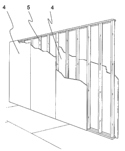
FIG. 4 is a perspective view of a fire wall or other fire resistive
assembly system of the invention of the invention having SCP panels 4 on
one side of a metal frame 5.
FIG. 5 is a perspective view of a fire wall or other fire resistive
assembly system of the invention of the invention having respective SCP
panels 4 attached to opposing sides of a metal frame 5.
Calcium Sulfate Hemihvdrate
Calcium sulfate hemihydrate, which may be used in panels of the
invention, is made from gypsum ore, a naturally occurring mineral, (calcium
sulfate dihydrate CaSO4.2H20). Unless otherwise indicated, "gypsum" will
refer to the dihydrate form of calcium sulfate. After being mined, the raw
gypsum is thermally processed to form a settable calcium sulfate, which may
be anhydrous, but more typically is the hemihydrate, CaSO4.1/2H20. For the
familiar end uses, the settable calcium sulfate reacts with water to solidify
by
forming the dihydrate (gypsum). The hemihydrate has two recognized
morphologies, termed alpha hemihydrate and beta hemihydrate. These are
selected for various applications based on their physical properties and cost.
Both forms react with water to form the dihydrate of calcium sulfate. Upon
hydration, alpha hemihydrate is characterized by giving rise to rectangular-
sided crystals of gypsum, while beta hemihydrate is characterized by
23
CA 02593435 2007-07-03
WO 2006/081156
PCT/US2006/002196
hydrating to produce needle-shaped crystals of gypsum, typically with large
aspect ratio. In the present invention either or both of the alpha or beta
forms
may be used depending on the mechanical performance desired. The beta
hemihydrate forms less dense microstructures and is preferred for low
density products. The alpha hemihydrate forms more dense microstructures
having higher strength and density than those formed by the beta
hemihydrate. Thus, the alpha hemihydrate could be substituted for beta
hemihydrate to increase strength and density or they could be combined to
adjust the properties.
A typical embodiment for the inorganic binder used to make panels of
the present invention comprises of hydraulic cement such as Portland
cement, high alumina cement, pozzolan-blended Portland cement, or
mixtures thereof.
Another typical embodiment for the inorganic binder used to make
panels of the present invention comprises a blend containing calcium sulfate
alpha hemihydrate, hydraulic cement, pozzolan, and lime.
Hydraulic Cement
ASTM defines "hydraulic cement" as follows: a cement that sets and
hardens by chemical interaction with water and is capable of doing so under
water. There are several types of hydraulic cements that are used in the
construction and building industries. Examples of hydraulic cements include
Portland cement, slag cements such as blast-furnace slag cement and super-
sulfated cements, calcium sulfoaluminate cement, high-alumina cement,
expansive cements, white cement, and rapid setting and hardening cements.
While calcium sulfate hemihydrate does set and harden by chemical
interaction with water, it is not included within the broad definition of
hydraulic
cements in the context of this invention. All of the aforementioned hydraulic
cements can be used to make the panels of the invention.
The most popular and widely used family of closely related hydraulic
cements is known as Portland cement. ASTM defines "Portland cement" as
a hydraulic cement produced by pulverizing clinker consisting essentially of
hydraulic calcium silicates, usually containing one or more of the forms of
calcium sulfate as an interground addition. To manufacture Portland cement,
24
CA 02593435 2007-07-03
WO 2006/081156
PCT/US2006/002196
an intimate mixture of limestone, argallicious rocks and clay is ignited in a
kiln
to produce the clinker, which is then further processed. As a result, the
following four main phases of Portland cement are produced: tricalcium
silicate (3CaO=S102, also referred to as C3S), dicalcium silicate (2CaO=Si02,
called C2S), tricalcium aluminate (3CaO.A1203 or C3A), and tetracalcium
aluminoferrite (4CaO.A1203=Fe203 or C4AF). Other compounds present in
minor amounts in Portland cement include calcium sulfate and other double
salts of alkaline sulfates, calcium oxide, and magnesium oxide. Of the
various recognized classes of Portland cement, Type Ill Portland cement
(ASTM classification) is preferred for making the panels of the invention,
because of its fineness it has been found to provide greater strength. The
other recognized classes of hydraulic cements including slag cements such
as blast-furnace slag cement and super-sulfated cements, calcium
sulfoaluminate cement, high-alumina cement, expansive cements, white
cement, rapidly setting and hardening cements such as regulated set cement
and VHE cement, and the other Portland cement types can also be
successfully used to make the panels of the present invention. The slag
cements and the calcium sulfoaluminate cement have low alkalinity and are
also suitable to make the panels of the present invention.
Fibers
Glass fibers are commonly used as insulating material, but they have
also been used as reinforcing materials with various matrices. The fibers
themselves provide tensile strength to materials that may otherwise be
subject to brittle failure. The fibers may break when loaded, but the usual
mode of failure of composites containing glass fibers occurs from
degradation and failure of the bond between the fibers and the continuous
phase material. Thus, such bonds are important if the reinforcing fibers are
to retain the ability to increase ductility and strengthen the composite over
time. It has been found that glass fiber reinforced cements do lose strength
as time passes, which has been attributed to attack on the glass by the lime
which is produced when cement is cured. One possible way to overcome
such attack is to cover the glass fibers with a protective layer, such as a
polymer layer. In general, such protective layers may resist attack by lime,
CA 02593435 2007-07-03
WO 2006/081156 PCT/US2006/002196
but it has been found that the strength is reduced in panels of the invention
and, thus, protective layers are not preferred. A more expensive way to limit
lime attack is to use special alkali-resistant glass fibers (AR glass fibers),
such as Nippon Electric Glass (NEG) 350Y. Such fibers have been found to
provide superior bonding strength to the matrix and are, thus, preferred for
panels of the invention. The glass fibers are monofilaments that have a
diameter from about 5 to 25 microns (micrometers) and typically about 10 to
microns (micrometers). The filaments generally are combined into 100
filament strands, which may be bundled into rovings containing about 50
10 strands. The strands or rovings will generally be chopped into suitable
filaments and bundles of filaments, for example, about 0.25 to 3 inches (6.3
to 76 mm) long, typically 1 to 2 inches (25 to 50 mm).
It is also possible to include other non-combustible fibers in the panels
of the invention, for example, steel fibers are also potential additives.
15 Pozzolanic Materials
As has been mentioned, most Portland and other hydraulic cements
produce lime during hydration (curing). It is desirable to react the lime to
reduce attack on glass fibers. It is also known that when calcium sulfate
hemihydrate is present, it reacts with tricalcium aluminate in the cement to
form ettringite, which can result in undesirable cracking of the cured
product.
This is often referred to in the art as "sulfate attack." Such reactions may
be
prevented by adding "pozzolanic" materials, which are defined in ASTM
C618-97 as". . . siliceous or siliceous and aluminous materials which in
themselves possess little or no cementitious value, but will, in finely
divided
form and in the presence of moisture, chemically react with calcium
hydroxide at ordinary temperatures to form compounds possessing
cementitious properties." One often used pozzolanic material is silica fume,
a finely divided amorphous silica which is the product of silicon metal and
ferro-silicon alloy manufacture. Characteristically, it has a high silica
content
and a low alumina content. Various natural and man-made materials have
been referred to as having pozzolanic properties, including pumice, perlite,
diatomaceous earth, tuff, trass, metakaolin, microsilica, ground granulated
blast furnace slag, and fly ash. While silica fume is a particularly
convenient
26
CA 02593435 2007-07-03
WO 2006/081156
PCT/US2006/002196
pozzolan for use in the panels of the invention, other pozzolanic materials
may be used. In contrast to silica fume, metakaolin, ground granulated blast
furnace slag, and pulverized fly ash have a much lower silica content and
large amounts of alumina, but can be effective pozzolanic materials. When
silica fume is used, it will constitute about 5 to 20 wt.%, preferably 10 to
15
wt.%, of the reactive powders (i.e., hydraulic cement, calcium sulfate alpha
hemihydrate, silica fume, and lime). If other pozzolans are substituted, the
amounts used will be chosen to provide chemical performance similar to
silica fume.
Liphtweipht Fillers/Microspheres
The lightweight panels employed in systems of the present invention
typically have a density of 65 to 90 pounds per cubic foot, preferably 65 to
85
pounds per cubic foot, more preferably 72 to 80 pounds per cubic foot. In
contrast, typical Portland cement based panels without wood fiber will have
densities in the 95 to 110 pcf range, while the Portland Cement based panels
with wood fibers will be about the same as SCP (about 65 to 85 pcf).
To assist in achieving these low densities the panels are provided with
lightweight filler particles. Such particles typically have an average
diameter
(average particle size) of about 10 to 500 microns (micrometers). More
typically they have a mean particle diameter (mean particle size) from 50 to
250 microns (micrometers) and/or fall within a particle diameter (size) range
of 10 to 500 microns. They also typically have a particle density (specific
gravity) in the range from 0.02 to 1.00. Microspheres or other lightweight
filler particles serve an important purpose in the panels of the invention,
which would otherwise be heavier than is desirable for building panels. Used
as lightweight fillers, the microspheres help to lower the average density of
the product. When the microspheres are hollow, they are sometimes
referred to as microballoons.
When the microspheres are hollow, they are sometimes referred to as
microballoons.
The microspheres are either non-combustible themselves or, if
combustible, added in sufficiently small amounts to not make the SCP panel
combustible. Typical lightweight fillers for including in mixtures employed to
27
CA 02593435 2007-07-03
WO 2006/081156
PCT/US2006/002196
make panels of the present invention are selected from the group consisting
of ceramic microspheres, polymer microspheres, perlite, glass microspheres,
and/or fly ash cenospheres.
Ceramic microspheres can be manufactured from a variety of
materials and using different manufacturing processes. Although a variety of
ceramic microspheres can be utilized as a filler component in the panels of
the invention, the preferred ceramic microspheres of the invention are
produced as a coal combustion by-product and are a component of the fly
ash found at coal fired utilities, for example, EXTENDOSPHERES-SG made
by Kish Company Inc., Mentor, Ohio or FILLITE Brand ceramic
microspheres made by Trelleborg Fillite Inc., Norcross, Georgia USA. The
chemistry of the preferred ceramic microspheres of the invention is
predominantly silica (Si02) in the range of about 50 to 75 wt.% and alumina
(A1203) in the range of about 15 to 40 wt.%, with up to 35 wt.% of other
materials. The preferred ceramic microspheres of the invention are hollow
spherical particles with diameters in the range of 10 to 500 microns
(micrometers), a shell thickness typically about 10% of the sphere diameter,
and a particle density preferably about 0.50 to 0.80 g/mL. The crushing
strength of the preferred ceramic microspheres of the invention is greater
than 1500 psi (10.3 MPa) and is preferably greater than 2500 psi (17.2 MPa).
Preference for ceramic microspheres in the panels of the invention
primarily stems from the fact that they are about three to ten times stronger
than most synthetic glass microspheres. In addition, the preferred ceramic
microspheres of invention are thermally stable and provide enhanced
dimensional stability to the panel of invention. Ceramic microspheres find
use in an array of other applications such as adhesives, sealants, caulks,
roofing compounds, PVC flooring, paints, industrial coatings, and high
temperature-resistant plastic composites. Although they are preferred, it
should be understood that it is not essential that the microspheres be hollow
and spherical, since it is the particle density and compressive strength which
provide the panel of the invention with its low weight and important physical
properties. Alternatively, porous irregular particles may be substituted,
provided that the resulting panels meet the desired performance.
= 28
CA 02593435 2007-07-03
WO 2006/081156
PCT/US2006/002196
The polymer microspheres, if present, are typically hollow spheres
with a shell made of polymeric materials such as polyacrylonitrile,
polymethacrylonitrile, polyvinyl chloride or polyvinylidine chloride, or
mixtures
thereof. The shell may enclose a gas used to expand the polymeric shell
during manufacture. The outer surface of the polymer microspheres may
have some type of an inert coating such as calcium carbonate, titanium
oxides, mica, silica, and talc. The polymer microspheres have a particle
density preferably about 0.02 to 0.15 g/mL and have diameters in the range
to 350 microns (micrometers). The presence of polymer microspheres
10 may facilitate simultaneous attainment of low panel density and enhanced
cutability and nailability.
Other lightweight fillers, for example glass microspheres, perlite or
hollow alumino-silicate cenospheres or microspheres derived from fly ash,
are also suitable for including in mixtures in combination with or in place of
ceramic microspheres employed to make panels of the present invention.
The glass microspheres typically are made of alkali resistant glass
materials and may be hollow. Typical glass microspheres are available from
GYPTEK INC., Suite 135, 16 Midlake Blvd SE, Calgary, AB, T2X 2X7,
CANADA.
In a first embodiment of the invention, only ceramic microspheres are
used throughout the full thickness of the panel. The panel typically contains
about 35 to 42 weight % of ceramic microspheres uniformly distributed
throughout the thickness of the panel.
In a second embodiment of the invention, a blend of lightweight
ceramic and glass microspheres is used throughout the full thickness of the
panel. The volume fraction of the glass microspheres in the panel of the
second embodiment of the invention will typically be in the range of 0 to 15%
of the total volume of the dry ingredients, where the dry ingredients of the
composition are the reactive powders (examples of reactive powders:
hydraulic cement only; blend of hydraulic cement and pozzolan; or blend of
hydraulic cement, calcium sulfate alpha hemihydrate, pozzolan, and lime),
ceramic microspheres, polymer microspheres, and alkali-resistant glass
29
CA 02593435 2007-07-03
WO 2006/081156
PCT/US2006/002196
fibers. A typical aqueous mixture has a ratio of water-to-reactive powders
from greater than 0.3/1 to 0.7/1.
If desired the panel may have a single layer as shown in FIG. 3.
However, the panel typically is made by a process which applies multiple
layers which, depending upon how the layers are applied and cured as well
as whether the layers have the same or different compositions, may or may
not in the final panel product retain distinct layers.
FIG. 6 shows a multi-layer structure of a panel 21 having layers 23,
25, 27 and 29. In the multi-layer structure the composition of the layers may
be the same or different. The typical thickness of the layer(s) ranges
between about 1/32 to 1.0 inches (about 0.75 to 25.4 mm). Where only one
outer layer is used, it typically will be less than 3/8 of the total panel
thickness.
FIGS. 6A - 6C illustrate a typical design and dimensions of tongue and
groove employed in a 1/4 inch (19.1 mm) thick SCP panel 4.
Typical Structures of Fire Walls and Other Fire Resistive Assemblies
As explained above, FIG. 4 is a perspective view of a fire wall or other
fire resistive assembly system of the invention having SCP panels 4 on one
side of the metal frame 5, and FIG. 5 is a perspective view of a fire wall or
other fire resistive assembly system of the invention of the invention having
SCP panels 4 respectively attached to opposing sides of the metal frame 5.
FIG. 7 is a side elevational view of single-layer SCP panels 4 of FIG. 3
supported on metal framing 5 of FIG. 5 in the system of the present
invention.
One type of fire resistive assembly for which the present invention is
suitable is as an area separation wall. Fig. 7 shows a solid area separation
wall of the present invention typically having a diaphragm of SCP panels 4 on
both sides of a metal frame 5. Area separation walls, especially the solid
area separation walls, may have one side that falls away to keep the
remaining frame and other diaphragms intact and standing. The SCP panels
may be attached with conventional break away aluminium clips if desired to
provide a wall in which one side may fall away while leaving the frame and or
other walls intact. Fig. 7 schematically shows fasteners 31 which could be
CA 02593435 2007-07-03
WO 2006/081156 PCT/US2006/002196
break away clips or other fasteners. In the present invention the break away
clips are optional because the SCP panel is not degraded by weather
exposure and is stronger and longer lasting than conventional gypsum board.
. Thus, in practice the panels 4 may be mechanically or adhesively
attached.
The present invention preferably achieves a water durable fire wall that may
also be a shear wall without having to provide bracing for the frame.
FIG. 7A shows a cavity wall of the present invention having two
parallel walls separated by a cavity 9. A typical cavity 9 provides a 2 inch
spacing. Each wall has diaphragms of SCP panels 4 on opposing sides of a
metal frame 5.
The fire resistant assemblies of the present invention may employ
SCP panels many framing configurations. For example, FIG. 7B shows a top
view of a solid area separation wall having two 3/4 inch thick SCP panels 4
set between USG H-studs 1 that are 24 inch on center. The wall is
positioned to provide a minimum of 3/4 inch air space on both sides
separating liner panels from adjacent framing (not shown).
FIG. 7C shows a top view of cavity area separation wall of the present
invention employing 1/2 or 3/4 inch thick SCP panels 4 positioned in USG 25
gauge C-H studs 3 that are 24 inches on center. This system has a single
layer of SCP panels 4 on each side applied vertically and screw attached.
Panels 4A may be gypsum panels, e.g., SHEETROCK Brand gypsum
panels, or SCP panels. Joints of the panels 4A are placed on opposing sides
of the framing and the perimeter is caulked.
Another specialized use of the system of the present invention is as a
shaft wall system. Thus, the shaft wall would have a metal frame to which
SCP panels are attached.
FIG. 7D shows an embodiment of a fire barrier wall employed as an
elevator shaft wall having SCP panels 4 attached to metal frame elements 5.
Shaft walls with racking shear strengths in the range of 200 plf to 2000 plf
(nominal ultimate racking strength) can be constructed using steel framing
combined with SCP panels. Shaft walls of this type can be assembled in the
following manner:
= 31
CA 02593435 2007-07-03
WO 2006/081156
PCT/US2006/002196
The steel wall frame is constructed to the appropriate size
adjacent to the shaft wall opening. The frame is typically built in the
horizontal position and then "tilted up" into place in the shaft wall
opening.
Any required shaft wall opening perimeter track and fasteners
are installed to receive the shaft wall.
The first layer of SCP panel is attached to the metal frame, with
the frame in the horizontal position. This layer of SCP panel is the
layer that faces the shaft wall opening.
The shaft wall frame with 1 layer of SCP panel is "tilted up" and
placed into position, covering the shaft wall opening.
The shaft wall frame with 1 layer of SCP panel is fastened to the
shaft opening perimeter track and/or to the primary structure around
the shaft opening.
The inside layer of the shaft wall is then applied to the steel
shaft wall frame using mechanical fasteners. This inside wall panel
can be an SCP panel (or more than 1 SCP panel), a gypsum panel (or
more than 1 gypsum panel), or a combination of panel layers.
FIG. 7E shows a stairwell wall employing SCP panels 4 attached to
metal frame elements 5.
FIG. 7F shows a mechanical shaft wall employing SCP panels 4
attached to metal frame elements 5.
FIG. 7G shows an air return shaft wall employing SCP panels 4
attached to metal frame elements 5.
FIG. 7H shows a top view of cavity area separation wall of the present
invention that may be employed in the embodiments of FIGS. 7D-G. This
employs 1/2 or 3/4 inch thick SCP panels 4 positioned in USG 25 gauge C-H
studs 3 that are 16 to 24 inches on center. This system has a single layer of
SCP panels 4 on each side of the stud 3 applied vertically and screw
attached. Panels 4A may be SHEETROCK Brand Gypsum panels or SCP
panels.
Fig 71 shows the embodiment of Fig. 7 modified to further comprise
gypsum or SCP panels 4A. In the embodiment of Fig. 71, the SCP panels 4
32
CA 02593435 2007-07-03
WO 2006/081156 PCT/US2006/002196
are typically attached to the metal framing 5 by fasteners, such as screws
(not shown) which do not break away. The SCP panels 4 are attached by
screws (not shown) to break away angle clips 146 which in turn are attached
by screws or nails (not shown) to studs 144. The panels 4A are attached by
screws or nails (not shown) to the studs 144 and/or other studs (not shown)
in a stud cavity 140A. Other break away fasteners which break or melt away
could substitute for the break away angle clips 146.
Fig. 7J shows the embodiment of Fig. 7A, having the cavity 9 between
opposed SCP panels 4, modified to further comprise gypsum or SCP panels
4A. In the embodiment of Fig. 7J, the SCP panels 4 are typically attached to
the metal framing 5 by fasteners, such as screws (not shown) which do not
break away. The SCP panels 4 are attached by screws (not shown) to break
away angle clips 146 which in turn are attached by screws or nails (not
shown) to studs 144. The panels 4A are attached by screws or nails (not
shown) to the studs 144 and/or other studs (not shown) in a stud cavity 140A.
Other break away fasteners which break or melt away could substitute for the
break away angle clips 146.
Fig. 7K shows a detailed illustration of an embodiment of a fire wall
130. Fire wall 130 extends from a roof deck 136 to a foundation (not
shown). The fire wall 130 has SCP panels 134 on opposed sides of metal
framing 132. A space 140 is located between the stud cavity 140A and the
respective SCP panel 134.
The roof deck 136 is supported by a roof rafters 133 (one shown) and
roof trusses 143 (one shown). Fire blocking 148 is provided, between top
plate studs 144B and roof rafters 133, on the opposed outer walls of the SCP
panels 134.
The floors 147 are supported by floor joists 131 which rest on 2 x 4
inch wooden studs 144. Fire blocking 148 is provided, between sill plate
studs 144A and floor joists 131, on the opposed outer walls of the SCP
panels 134. Horizontal gypsum ceiling panels 138 and vertical gypsum wall
panels 145 are also provided. Sealant 139 is provided at a lower end of the
vertical gypsum wall panels behind moldings 139A.
33
CA 02593435 2007-07-03
WO 2006/081156
PCT/US2006/002196
Fire blocking 135 and fire blocking 137, such as THERMAFIBER
SAFB sound attenuating fiber blankets, may also be provided. A notable
feature of this embodiment is that the aluminum angle clips 146 are attached
by screws to the SCP panels 134 and studs, e.g., sill plate studs 144A and
top plate studs 144B. The aluminum clips 146 can break away or melt in the
event of a fire so the structure on fire can fall away from the SCP panels 134
of the fire wall.
Another fire resistive assembly of the present invention is a garage
adjacent the living quarters of a house having walls and a ceiling built of
SCP
panels and metal framing.
Formulation of SCP Panels
The components used to make the shear resistant panels of the
invention are hydraulic cement, calcium sulfate alpha hemihydrate, an active
pozzolan such as silica fume, lime, ceramic microspheres, alkali-resistant
glass fibers, superplasticizer (e.g., sodium salt of polynapthalene
sulfonate),
and water. Typically, both hydraulic cement and calcium sulfate alpha
hemihydrate are present. Long term durability of the composite is
compromised if calcium sulfate alpha hemihydrate is not present along with
silica fume. Water/moisture durability is compromised when Portland cement
is not present. Small amounts of accelerators and/or retarders may be
added to the composition to control the setting characteristics of the green
(i.e., uncured) material. Typical non-limiting additives include accelerators
for
hydraulic cement such as calcium chloride, accelerators for calcium sulfate
alpha hemihydrate such as gypsum, retarders such as DTPA (diethylene
triamine pentacetic acid), tartaric acid or an alkali salt of tartaric acid
(e.g.,
potassium tartrate), shrinkage reducing agents such as glycols, and
entrained air.
Panels of the invention will include a continuous phase in which alkali-
resistant glass fibers and light weight filer, e.g., microspheres, are
uniformly
distributed. The continuous phase results from the curing of an aqueous
mixture of the reactive powders, i.e., blend of hydraulic cement, calcium
sulfate alpha hemihydrate, pozzolan, and lime), preferably including
superplasticizer and/or other additives.
34
CA 02593435 2007-07-03
WO 2006/081156
PCT/US2006/002196
Typical weight proportions of embodiments of the reactive powders
(inorganic binder), e.g., hydraulic cement, calcium sulfate alpha hemihydrate,
pozzolan and lime, in the invention, based on dry weight of the reactive
powders, are shown in TABLE 1. TABLE 1A lists typical ranges of reactive
powders, lightweight filler, and glass fibers in compositions of the present
invention.
TABLE 1
Reactive Powder Weight Proportion (%)
Broad Typical
Hydraulic Cement 20-55 25-40
Calcium Sulfate Alpha 35-75 45-65
Hemihydrate
Pozzolan 5-25 10-15
Lime up to 3.5 or 0.75-1.25
0.2 to 3.5
TABLE 1A
SCP Composition (dry basis) Typical Weight Typical Weight
Proportion (%) Proportion (%)
Reactive Powder 35-70 35-68
Lightweight Filler 20-50 23-49
Glass Fibers 5-20 5-17
Lime is not required in all formulations of the invention, but it has been
found that adding lime provides superior panels and it usually will be added
in amounts greater than about 0.2 wt.%. Thus, in most cases, the amount of
lime in the reactive powders will be about 0.2 to 3.5 wt.%.
In the first embodiment of the invention, the dry ingredients of the
composition will be the reactive powders (i.e., blend of hydraulic cement,
calcium sulfate alpha hemihydrate, pozzolan, and lime), ceramic
microspheres and alkali-resistant glass fibers, and the wet ingredients of the
composition will be water and superplasticizer. The dry ingredients and the
CA 02593435 2007-07-03
WO 2006/081156 PCT/US2006/002196
wet ingredients are combined to produce the panel of the invention. The
ceramic microspheres are uniformly distributed in the matrix throughout the
full thickness of the panel. Of the total weight of dry ingredients, the panel
of
the invention is formed from about 49 to 56 wt.% reactive powders, 35 to 42
wt.% ceramic microspheres and 7 to 12 wt.% alkali-resistant glass fibers. In
a broad range, the panel of the invention is formed from 35 to 58 wt.%
reactive powders, 34 to 49 wt.% lightweight filler, e.g., ceramic
microspheres,
and 6 to 17 wt.% alkali-resistant glass fibers of the total dry ingredients.
The
amounts of water and superplasticizer added to the dry ingredients will be
sufficient to provide the desired slurry fluidity needed to satisfy processing
considerations for any particular manufacturing process. The typical addition
rates for water range between 35 to 60% of the weight of reactive powders
and those for superplasticizer range between 1 to 8% of the weight of
reactive powders.
The glass fibers are monofilaments having a diameter of about 5 to 25
microns (micrometers), preferably about 10 to 15 microns (micrometers).
The monofilaments typically are combined in 100 filament strands, which
may be bundled into rovings of about 50 strands. The length of the glass
fibers will typically be about 0.25 to 1 or 2 inches (6.3 to 25 or 50 mm) or
about 1 to 2 inches (25 to 50 mm) and broadly about 0.25 to 3 inches (6.3 to
76 mm). The fibers have random orientation, providing isotropic mechanical
behavior in the plane of the panel.
The second embodiment of the invention contains a blend of ceramic
and glass microspheres uniformly distributed throughout the full thickness of
the panel. Accordingly, in the second embodiment of the invention, the dry
ingredients of the composition will be the reactive powders (hydraulic
cement, calcium sulfate alpha hemihydrate, pozzolan, and lime), ceramic
microspheres, glass microspheres, and alkali-resistant glass fibers, and the
wet ingredients of the composition will be water and superplasticizer. The
dry ingredients and the wet ingredients will be combined to produce the panel
of the invention. The volume fraction of the glass microspheres in the panel
will typically be in the range of 7 to 15% of the total volume of dry
ingredients.
Of the total weight of dry ingredients, the panel of the invention is formed
36
CA 02593435 2007-07-03
WO 2006/081156 PCT/US2006/002196
from about 54 to 65 wt.% reactive powders, 25 to 35 wt.% ceramic
microspheres, 0.5 to 0.8 wt.% glass microspheres, and 6 to 10 wt.% alkali-
resistant glass fibers. In the broad range, the panel of the invention is
formed
from 42 to 68 wt.% reactive powders, 23 to 43 wt.% lightweight fillers, e.g.,
ceramic microspheres, 0.2 to 1.0 wt.% glass microspheres, and 5 to 15 wt.%
alkali-resistant glass fibers, based on the total dry ingredients. The amounts
of water and superplasticizer added to the dry ingredients will be adjusted to
provide the desired slurry fluidity needed to satisfy the processing
considerations for any particular manufacturing process. The typical addition
rates for water range between 35 to 70% of the weight of reactive powders,
but could be greater than 60% up to 70% (weight ratio of water to reactive
powder of 0.6/1 to 0.7/1), preferably 65% to 75%, when it is desired to use
the ratio of water-to-reactive powder to reduce panel density and improve
cutability. The amount of superplasticizer will range between 1 to 8% of the
weight of reactive powders. The glass fibers are monofilaments having a
diameter of about 5 to 25 microns (micrometers), preferably about 10 to 15
microns (micrometers). They typically are bundled into strands and rovings
as discussed above. The length of the glass fibers typically is about 1 to 2
inches (25 to 50 mm) and broadly about 0.25 to 3 inches (6.3 to 76 mm).
The fibers will have random orientation providing isotropic mechanical
behavior in the plane of the panel.
In the third embodiment of the invention, a multi-layer structure in the
panel is created where the outer layer(s) have improved nailability (fastening
ability)/cutability. This is achieved by increasing the water-to-cement ratio
in
the outer layer(s), and/or changing the amount of filler, and/or adding an
amount of polymer microspheres sufficiently small such that the panel
remains noncombustible. The core of the panel will typically contain ceramic
microspheres uniformly distributed throughout the layer thickness or
alternatively, a blend of one or more of ceramic microspheres, glass
microspheres and fly ash cenospheres.
The dry ingredients of the core layer of this embodiment of the present
invention will be the reactive powders (typically hydraulic cement, calcium
sulfate alpha hemihydrate, pozzolan, and lime), lightweight filler particles
37
CA 02593435 2007-07-03
WO 2006/081156 PCT/US2006/002196
(typically microspheres such as ceramic microspheres alone or one or more
of ceramic microspheres, glass microspheres and fly ash cenospheres), and
alkali-resistant glass fibers, and the wet ingredients of the core layer are
water and superplasticizer. The dry ingredients and the wet ingredients will
be combined to produce the core layer of the panel of the invention. Of the
total weight of dry ingredients, the core of the panel of the invention
preferably is formed from about 49 to 56 wt.% reactive powders, 35 to 42
wt.% hollow ceramic microspheres and 7 to 12 wt.% alkali-resistant glass
fibers, or alternatively, about 54 to 65 wt.% reactive powders, 25 to 35 wt.%
ceramic microspheres, 0.5 to 0.8 wt.% glass microspheres or fly ash
cenospheres, and 6 to 10 wt.% alkali-resistant glass fibers. In the broad
range, the core layer of the panel of this embodiment of the present invention
is typically formed by about 35 to 58 wt.% reactive powders, 34 to 49 wt.%
lightweight fillers, e.g., ceramic microspheres, and 6 to 17 wt.% alkali-
resistant glass fibers, based on the total dry ingredients, or alternatively,
about 42 to 68 wt.% of reactive powders, 23 to 43 wt.% ceramic
microspheres, up to 1.0 wt.%, preferably 0.2 to 1.0 wt.%, other lightweight
filler, e.g., glass microspheres or fly ash cenospheres, and 5 to 15 wt.%
alkali-resistant glass fibers. The amounts of water and superplasticizer
added to the dry ingredients will be adjusted to provide the desired slurry
fluidity needed to satisfy the processing considerations for any particular
manufacturing process. The typical addition rates for water will range
between 35 to 70% of the weight of reactive powders but will be greater than
60% up to 70% when it is desired to use the ratio of water-to-reactive
powders to reduce panel density and improve nailability and those for
superplasticizer will range between 1 to 8% of the weight of reactive
powders. When the ratio of water-to-reactive powder is adjusted, the slurry
composition will be adjusted to provide the panel of the invention with the
desired properties.
There is generally an absence of polymer microspheres and an
absence of polymer fibers, e.g. poly vinyl alcohol fibers, that would cause
the
SCP panel to become combustible.
38
=
CA 02593435 2007-07-03
WO 2006/081156
PCT/US2006/002196
The dry ingredients of the outer layer(s) of this embodiment of the
present invention will be the reactive powders (typically hydraulic cement,
calcium sulfate alpha hemihydrate, pozzolan, and lime), lightweight filler
particles (typically microspheres such as ceramic microspheres alone or one
or more of ceramic microspheres, glass microspheres and fly ash
cenospheres), and alkali-resistant glass fibers, and the wet ingredients of
the
outer layer(s) will be water and superplasticizer. The dry ingredients and the
wet ingredients are combined to produce the outer layers of the panel of the
invention. In the outer layer(s) of the panel of this embodiment of the
present
invention, the amount of water is selected to furnish good fastening and
cutting ability to the panel. Of the total weight of dry ingredients, the
outer
layer(s) of the panel of the invention preferably are formed from about 54 to
65 wt.% reactive powders, 25 to 35 wt.% ceramic microspheres, 0 to 0.8
wt.% glass microspheres, and 6 to 10 wt.% alkali-resistant glass fibers. In
the broad range, the outer layers of the panel of the invention are formed
from about 42 to 68 wt.% reactive powders, 23 to 43 wt.% ceramic
microspheres, up to 1.0 wt.% glass microspheres (and/or fly ash
cenospheres), and 5 to 15 wt.% alkali-resistant glass fibers, based on the
total dry ingredients. The amounts of water and superplasticizer added to the
dry ingredients are adjusted to provide the desired slurry fluidity needed to
satisfy the processing considerations for any particular manufacturing
process. The typical addition rates for water range between 35 to 70% of the
weight of reactive powders and particularly greater than 60% up to 70%
when the ratio of water-to-reactive powders is adjusted to reduce panel
density and improve nailability, and typical addition rates for
superplasticizer
will range between 1 to 8% of the weight of reactive powders. The preferable
thickness of the outer layer(s) ranges between 1/32 to 4/32 inches (0.8 to 3.2
mm) and the thickness of the outer layer when only one is used will be less
than 3/8 of the total thickness of the panel.
In both the core and outer layer(s) of this embodiment of the present
invention, the glass fibers are monofilaments having a diameter of about 5 to
25 microns (micrometers), preferably 10 to 15 microns (micrometers). The
monofilaments typically are bundled into strands and rovings as discussed
39
CA 02593435 2007-07-03
WO 2006/081156 PCT/US2006/002196
above. The length typically is about 1 to 2 inches (25 to 50 mm) and broadly
about 0.25 to 3 inches (6.3 to 76 mm). The fiber orientation will be random,
providing isotropic mechanical behavior in the plane of the panel.
The invention also includes a fourth embodiment of a multi-layer panel
having a density of 65 to 90 pounds per cubic foot and capable of resisting
shear loads when fastened to framing and comprising a core layer of a
continuous phase resulting from the curing of an aqueous mixture, a
continuous phase resulting from the curing of an aqueous mixture
comprising, on a dry basis, 35 to 70 weight % reactive powder, 20 to 50
weight percent lightweight filler, and 5 to 20 weight % glass fibers, the
continuous phase being reinforced with glass fibers and containing the
lightweight filler particles, the lightweight filler particles having a
particle
specific gravity of from 0.02 to 1.00 and an average particle size of about 10
to 500 microns (micrometers); and at least one outer layer of respectively
another continuous phase resulting from the curing of an aqueous mixture
comprising, on a dry basis, 35 to 70 weight % reactive powder, 20 to 50
weight percent lightweight filler, and 5 to 20 weight % glass fibers, the
continuous phase being reinforced with glass fibers and containing the
lightweight filler particles, the lightweight filler particles having a
particle
specific gravity of from 0.02 to 1.00 and an average particle size of about 10
to 500 microns (micrometers) on each opposed side of the inner layer,
wherein the at least one outer layer has a higher percentage of glass fibers
than the inner layer.
Making A Panel Of The Invention
The reactive powders, e.g., blend of hydraulic cement, calcium sulfate
alpha hemihydrate, pozzolan, and lime), and lightweight filler, e.g.,
microspheres, are blended in the dry state in a suitable mixer.
Then, water, a superplasticizer (e.g., the sodium salt of
polynapthalene sulfonate), and the pozzolan (e.g., silica fume or metakaolin)
are mixed in another mixer for 1 to 5 minutes. If desired, a retarder (e.g.,
potassium tartrate) is added at this stage to control the setting
characteristics
of the slurry. The dry ingredients are added to the mixer containing the wet
CA 02593435 2007-07-03
WO 2006/081156 PCT/US2006/002196
ingredients and mixed for 2 to 10 minutes to form smooth homogeneous
slurry.
The slurry is then combined with glass fibers, in any of several ways,
with the objective of obtaining a uniform slurry mixture. The cementitious
panels are then formed by pouring the slurry containing fibers into an
appropriate mold of desired shape and size. If necessary, vibration is
provided to the mold to obtain good compaction of material in the mold. The
panel is given required surface finishing characteristics using an appropriate
screed bar or trowel.
One of a number of methods to make multi-layer SCP panels is as
follows. The reactive powders, e.g., blend of hydraulic cement, calcium
sulfate alpha hemihydrate, pozzolan, and lime), and lightweight filler, e.g.,
microspheres, are blended in the dry state in a suitable mixer. Then, water, a
superplasticizer (e.g., the sodium salt of polynapthalene sulfonate), and the
pozzolan (e.g., silica fume or metakaolin) are mixed in another mixer for Ito
5 minutes. If desired, a retarder (e.g., potassium tartrate) is added at this
stage to control the setting characteristics of the slurry. The dry
ingredients
are added to the mixer containing the wet ingredients and mixed for 2 to 10
minutes to form a smooth homogeneous slurry.
The slurry may be combined with the glass fibers in several ways, with
the objective of obtaining a uniform mixture. The glass fibers typically will
be
in the form of rovings that are chopped into short lengths. In a preferred
embodiment, the slurry and the chopped glass fibers are concurrently
sprayed into a panel mold. Preferably, spraying is done in a number of
passes to produce thin layers, preferably up to about 0.25 inches (6.3 mm)
thick, which are built up into a uniform panel having no particular pattern
and
with a thickness of 1/4 to 1 inch (6.3 to 25.4 mm). For example, in one
application, a 3 x 5 ft (0.91 x 1.52 m) panel was made with six passes of the
spray in the length and width directions. As each layer is deposited, a roller
may be used to assure that the slurry and the glass fibers achieve intimate
contact. The layers may be leveled with a screed bar or other suitable
means after the rolling step. Typically, compressed air will be used to
atomize the slurry. As it emerges from the spray nozzle, the slurry mixes
41
CA 02593435 2013-04-19
with glass fibers that have been cut from a roving by a chopper mechanism
mounted on the spray gun. The uniform mixture of slurry and glass fibers is
deposited in the panel mold as described above.
If desired the outer surface layers of the panel may contain polymer
spheres, or be otherwise constituted, in order that the fasteners used to
attach the panel to framing can be driven easily. The preferable thickness of
such layers will be about 1/32 inches to 4/32 inches (0.8 to 3.2 mm). The
same procedure described above by which the core of the panel is made
may be used to apply the outer layers of the panel.
Other methods of depositing a mixture of the slurry and glass fibers
will occur to those familiar with the panel-making art. For example, rather
than using a batch process to make each panel, a continuous sheet may be
prepared in a similar manner, which after the material has sufficiently set,
can
be cut into panels of the desired size. The percentage of fibers relative to
the
volume of slurry typically constitutes approximately in the range of 0.5% to
3%, for example 1.6%. Typical panels have a thickness of about 1/4 to 1-1/2
inches (6.3 to 38.1 mm).
Another method of making panels of the present invention is by using =
the process steps disclosed in US patent number 7,455,738.
US patent number 7,455,738 discloses after one of
an initial deposition of loosely distributed, chopped fibers or a layer of
slurry
upon a moving web, fibers are deposited upon the slurry layer. An
embedment device compacts the recently deposited fibers into the slurry,
after which additional layers of slurry, then chopped fibers are added,
followed by more embedment. The process is repeated for each layer of the
board, as desired. Upon completion, the board has a more evenly distributed
fiber component, which results in relatively strong panels without the need
for
thick mats of reinforcing fibers, as taught in prior art production techniques
for
cementitious panels.
More specifically, US patent application number 10/666,294 discloses
a multi-layer process for producing structural cementitious panels, including:
(a.) providing a moving web; (b.) one of depositing a first layer of loose
fibers
42
CA 02593435 2007-07-03
WO 2006/081156 PCT/US2006/002196
and (c.) depositing a layer of settable slurry upon the web; (d.) depositing a
second layer of loose fibers upon the slurry; (e.) embedding the second layer
of fibers into the slurry; and (f.) repeating the slurry deposition of step
(c.)
through step (d.) until the desired number of layers of settable fiber-
enhanced
slurry in the panel is obtained.
FIG. 21 is a diagrammatic elevational view of an apparatus which is
suitable for performing the process of US patent application number
10/666,294. Referring now to FIG. 21, a structural panel production line is
diagrammatically shown and is generally designated 310. The production
line 310 includes a support frame or forming table 312 having a plurality of
legs 313 or other supports. Included on the support frame 312 is a moving
carrier 314, such as an endless rubber-like conveyor belt with a smooth,
water-impervious surface, however porous surfaces are contemplated. As is
well known in the art, the support frame 312 may be made of at least one
table-like segment, which may include designated legs 313. The support
frame 312 also includes a main drive roll 316 at a distal end 318 of the
frame,
and an idler roll 320 at a proximal end 322 of the frame. Also, at least one
belt tracking and/or tensioning device 324 is preferably provided for
maintaining a desired tension and positioning of the carrier 314 upon the
rolls
316, 320.
Also, in the preferred embodiment, a web 326 of Kraft paper, release
paper, and/or other webs of support material designed for supporting slurry
prior to setting, as is well known in the art, may be provided and laid upon
the
carrier 314 to protect it and/or keep it clean. However, it is also
contemplated
that the panels produced by the present line 310 are formed directly upon the
carrier 314. In the latter situation, at least one belt washing unit 328 is
provided. The carrier 314 is moved along the support frame 312 by a
combination of motors, pulleys, belts or chains which drive the main drive
roll
316 as is known in the art. It is contemplated that the speed of the carrier
314 may vary to suit the application.
In the apparatus of FIG. 21, structural cementitious panel production is
initiated by one of depositing a layer of loose, chopped fibers 330 or a layer
of slurry upon the web 326. An advantage of depositing the fibers 330 before
43
CA 02593435 2007-07-03
WO 2006/081156 PCT/US2006/002196
the first deposition of slurry is that fibers will be embedded near the outer
surface of the resulting panel. A variety of fiber depositing and chopping
devices are contemplated by the present line 310, however the preferred
system employs at least one rack 331 holding several spools 332 of
fiberglass cord, from each of which a cord 334 of fiber is fed to a chopping
station or apparatus, also referred to as a chopper 336.
The chopper 336 includes a rotating bladed roll 338 from which project
radially extending blades 340 extending transversely across the width of the
carrier 314, and which is disposed in close, contacting, rotating relationship
with an anvil roll 342. In the preferred embodiment, the bladed roll 338 and
the anvil roll 342 are disposed in relatively close relationship such that the
rotation of the bladed roll 338 also rotates the anvil roll 342, however the
reverse is also contemplated. Also, the anvil roll 342 is preferably covered
with a resilient support material against which the blades 340 chop the cords
334 into segments. The spacing of the blades 340 on the roll 338 determines
the length of the chopped fibers. As is seen in FIG. 21, the chopper 336 is
disposed above the carrier 314 near the proximal end 322 to maximize the
productive use of the length of the production line 310. As the fiber cords
334 are chopped, the fibers 330 fall loosely upon the carrier web 326.
Next, a slurry feed station, or a slurry 'feeder 344 receives a supply of
slurry 346 from a remote mixing location 347 such as a hopper, bin or the
like. It is also contemplated that the process may begin with the initial
deposition of slurry upon the carrier 314. The slurry is preferably comprised
of varying amounts of Portland cement, gypsum, aggregate, water,
accelerators, plasticizers, foaming agents, fillers and/or other ingredients,
and described above and in the patents listed above which have been
incorporated by reference for producing SCP panels. The relative amounts
of these ingredients, including the elimination of some of the above or the
addition of others, may vary to suit the use.
While various configurations of slurry feeders 344 are contemplated
which evenly deposit a thin layer of slurry 346 upon the moving carrier 314,
the preferred slurry feeder 344 includes a main metering roll 348 disposed
transversely to the direction of travel of the carrier 314. A companion or
back
44
CA 02593435 2007-07-03
WO 2006/081156 PCT/US2006/002196
up roll 350 is disposed in close parallel, rotational relationship to the
metering
roll 348 to form a nip 352 there between. A pair of sidewalls 354, preferably
of non-stick material such as Teflon brand material or the like, prevents
slurry 346 poured into the nip 352 from escaping out the sides of the feeder
344.
The feeder 344 deposits an even, relatively thin layer of the slurry 346
upon the moving carrier 314 or the carrier web 326. Suitable layer
thicknesses range from about 0.05 inch to 0.20 inch. However, with four
layers preferred in the preferred structural panel produced by the present
process, and a suitable building panel being approximately 0.5 inch, an
especially preferred slurry layer thickness is approximately 0.125 inch.
Referring now to FIGs. 21 and 22, to achieve a slurry layer thickness
as described above, several features are provided to the slurry feeder 344.
First, to ensure a uniform disposition of the slurry 346 across the entire web
326, the slurry is delivered to the feeder 344 through a hose 356 located in a
laterally reciprocating, cable driven, fluid powered dispenser 358 of the type
well known in the art. Slurry flowing from the hose 356 is thus poured into
the feeder 344 in a laterally reciprocating motion to fill a reservoir 359
defined
by the rolls 348, 350 and the sidewalls 354. Rotation of the metering roll 348
thus draws a layer of the slurry 346 from the reservoir.
Next, a thickness monitoring or thickness control roll 360 is disposed
slightly above and/or slightly downstream of a vertical centerline of the main
metering roll 348 to regulate the thickness of the slurry 346 drawn from the
feeder reservoir 357 upon an outer surface 362 of the main metering roll 348.
Also, the thickness control roll 360 allows handling of slurries with
different
and constantly changing viscosities. The main metering roll 348 is driven in
the same direction of travel "T" as the direction of movement of the carrier
314 and the carrier web 326, and the main metering roll 348, the backup roll
350 and the thickness monitoring roll 360 are all rotatably driven in the same
direction, which minimizes the opportunities for premature setting of slurry
on
the respective moving outer surfaces. As the slurry 346 on the outer surface
362 moves toward the carrier web 326, a transverse stripping wire 364
located between the main metering roll 348 and the carrier web 326 ensures
CA 02593435 2007-07-03
WO 2006/081156 PCT/US2006/002196
that the slurry 346 is completely deposited upon the carrier web and does not
proceed back up toward the nip 352 and the feeder reservoir 359. The
stripping wire 364 also helps keep the main metering roll 348 free of
prematurely setting slurry and maintains a relatively uniform curtain of
slurry.
A second chopper station or apparatus 366, preferably identical to the
chopper 336, is disposed downstream of the feeder 344 to deposit a second
layer of fibers 368 upon the slurry 346. In the preferred embodiment, the
chopper apparatus 366 is fed cords 334 from the same rack 331 that feeds
the chopper 336. However, it is contemplated that separate racks 331 could
be supplied to each individual chopper, depending on the application.
Referring now to FIGs. 21 and 23, next, an embedment device,
generally designated 370 is disposed in operational relationship to the slurry
346 and the moving carrier 314 of the production line 310 to embed the fibers
368 into the slurry 346. While a variety of embedment devices are
contemplated, including, but not limited to vibrators, sheep's foot rollers
and
the like, in the preferred embodiment, the embedment device 370 includes at
least a pair of generally parallel shafts 372 mounted transversely to the
direction of travel "T" of the carrier web 326 on the frame 312. Each shaft
372 is provided with a plurality of relatively large diameter disks 374 which
are axially separated from each other on the shaft by small diameter disks
376.
During SCP panel production, the shafts 372 and the disks 374, 376
rotate together about the longitudinal axis of the shaft. As is well known in
the art, either one or both of the shafts 372 may be powered, and if only one
is powered, the other may be driven by belts, chains, gear drives or other
known power transmission technologies to maintain a corresponding
direction and speed to the driving roll. The respective disks 374, 376 of the
adjacent, preferably parallel shafts 372 are intermeshed with each other for
creating a "kneading" or "massaging" action in the slurry, which embeds the
fibers 368 previously deposited thereon. In addition, the close, intermeshed
and rotating relationship of the disks 372, 374 prevents the buildup of slurry
346 on the disks, and in effect creates a "self-cleaning" action which
46
CA 02593435 2007-07-03
WO 2006/081156 PCT/US2006/002196
significantly reduces production line downtime due to premature setting of
clumps of slurry.
The intermeshed relationship of the disks 374, 376 on the shafts 372
includes a closely adjacent disposition of opposing peripheries of the small
diameter spacer disks 376 and the relatively large diameter main disks 374,
which also facilitates the self-cleaning action. As the disks 374, 376 rotate
relative to each other in close proximity (but preferably in the same
direction),
it is difficult for particles of slurry to become caught in the apparatus and
prematurely set. By providing two sets of disks 374 which are laterally offset
relative to each other, the slurry 346 is subjected to multiple acts of
disruption, creating a "kneading" action which further embeds the fibers 368
in the slurry 346.
Once the fibers 368 have been embedded, or in other words, as the
moving carrier web 326 passes the embedment device 370, a first layer 377
of the SCP panel is complete. In the preferred embodiment, the height or
thickness of the first layer 377 is in the approximate range of 0.05-0.20
inches. This range has been found to provide the desired strength and
rigidity when combined with like layers in a SCP panel. However, other
thicknesses are contemplated depending on the application.
To build a structural cementitious panel of desired thickness,
additional layers are needed. To that end, a second slurry feeder 378, which
is substantially identical to the feeder 344, is provided in operational
relationship to the moving carrier 314, and is disposed for deposition of an
additional layer 380 of the slurry 346 upon the existing layer 377.
Next, an additional chopper 382, substantially identical to the
choppers 336 and 366, is provided in operational relationship to the frame
312 to deposit a third layer of fibers 384 provided from a rack (not shown)
constructed and disposed relative to the frame 312 in similar fashion to the
rack 331. The fibers 384 are deposited upon the slurry layer 380 and are
embedded using a second embedment device 386. Similar in construction
and arrangement to the embedment device 370, the second embedment
device 386 is mounted slightly higher relative to the moving carrier web 314
47
CA 02593435 2007-07-03
WO 2006/081156
PCT/US2006/002196
so that the first layer 377 is not disturbed. In this manner, the second layer
380 of slurry and embedded fibers is created.
Referring now to FIG. 21, with each successive layer of settable slurry
and fibers, an additional slurry feeder station 344, 378, 402 followed by a
fiber chopper 336, 366, 382, 404 and an embedment device 370, 386, 406 is
provided on the production line 310. In the preferred embodiment, four total
layers (see for example, the panel 101 of Fig. 29) are provided to form the
SCP panel. Upon the disposition of the four layers of fiber-embedded
settable slurry as described above, a forming device 394 is preferably
provided to the frame 312 to shape an upper surface 396 of the panel. Such
forming devices 394 are known in the settable slurry/board production art,
and typically are spring-loaded or vibrating plates which conform the height
and shape of the multi-layered panel to suit the desired dimensional
characteristics.
The panel which is made has multiple layers (see for example layers
23, 25, 27, 29 of panel 21 of Fig. 6) which upon setting form an integral,
fiber-
reinforced mass. Provided that the presence and placement of fibers in each
layer are controlled by and maintained within certain desired parameters as
is disclosed and described below, it will be virtually impossible to
delaminate
the panel.
At this point, the layers of slurry have begun to set, and the respective
panels are separated from each other by a cutting device 398, which in the
preferred embodiment is a water jet cutter. Other cutting devices, including
moving blades, are considered suitable for this operation, provided that they
can create suitably sharp edges in the present panel composition. The
cutting device 398 is disposed relative to the line 310 and the frame 312 so
that panels are produced having a desired length, which may be different
from the representation shown in FIG. 21. Since the speed of the carrier web
314 is relatively slow, the cutting device 398 may be mounted to cut
perpendicularly to the direction of travel of the web 314. With faster
production speeds, such cutting devices are known to be mounted to the
production line 310 on an angle to the direction of web travel. Upon cutting,
48
CA 02593435 2007-07-03
WO 2006/081156
PCT/US2006/002196
the separated panels 321 are stacked for further handling, packaging,
storage and/or shipment as is well known in the art.
In quantitative terms, the influence of the number of fiber and slurry
layers, the volume fraction of fibers in the panel, and the thickness of each
slurry layer, and fiber strand diameter on fiber embedment efficiency has
been investigated. In the analysis, the following parameters were identified:
VT = Total composite volume
vs = Total panel slurry volume
v =
Total panel fiber volume
vf Total fiber volume/layer
>1
VTj Total composite volume/layer
vsj = Total slurry volume/layer
= Total number of slurry layers; Total number of fiber
layers
Vf = Total panel fiber volume fraction
df = Equivalent diameter of individual fiber strand
f Length of individual fiber strand
t = Panel thickness
= Total thickness of individual layer including slurry and
fibers
ts) = Thickness of individual slurry layer
nu, flfl,I, nf2,1 = Total number of fibers in a fiber layer
P P P
Sf,1) sfp Sf2,1 Total projected surface area of fibers
contained in a fiber layer
SP P SP
fj, S Al, /2,1 Projected fiber surface area fraction for a
fiber layer.
49
CA 02593435 2007-07-03
WO 2006/081156 PCT/US2006/002196
Projected Fiber Surface Area Fraction, S;)
Assume a panel composed of equal number of slurry and fiber layers.
Let the number of these layers be equal to N1, and the fiber volume fraction
in the panel be equal to VI.
In summary, the projected fiber surface area fraction, SfP,1 of a layer of
fiber network being deposited over a distinct slurry layer is given by the
following mathematical relationship:
SP/ 4V ft = __ 4V1*ts'l
f' rN1d. gd f (1¨ V 1)
where, Vf is the total panel fiber volume fraction, t is the total panel
thickness, df is the diameter of the fiber strand, N is the total number of
fiber layers and tsf is the thickness of the distinct slurry layer being used.
Accordingly, to achieve good fiber embedment efficiency, the objective
function becomes keeping the fiber surface area fraction below a certain
critical value. It is noteworthy that by varying one or more variables
appearing in the Equations 8 and 10, the projected fiber surface area fraction
can be tailored to achieve good fiber embedment efficiency.
Different variables that affect the magnitude of projected fiber surface
area fraction are identified and approaches have been suggested to tailor the
magnitude of "projected fiber surface area fraction" to achieve good fiber
embedment efficiency. These approaches involve varying one or more of the
following variables to keep projected fiber surface area fraction below a
critical threshold value: number of distinct fiber and slurry layers,
thickness
of distinct slurry layers and diameter of fiber strand.
Based on this fundamental work, the preferred magnitudes of the
projected fiber surface area fraction, SfPj have been discovered to be as
follows:
Preferred projected fiber surface area fraction, SfP) <0.65
50 =
CA 02593435 2007-07-03
WO 2006/081156 PCT/US2006/002196
Most preferred projected fiber surface area fraction, Sc; <0.45
For a design panel fiber volume fraction, Ti;., achievement of the
aforementioned preferred magnitudes of projected fiber surface area fraction
can be made possible by tailoring one or more of the following variables ¨
total number of distinct fiber layers, thickness of distinct slurry layers and
fiber strand diameter. In particular, the desirable ranges for these variables
that lead to the preferred magnitudes of projected fiber surface area fraction
are as follows:
Thickness of Distinct Slurry Layers in Multiple Layer SCP panels, tsf
Preferred thickness of distinct slurry layers, tsi inches
More Preferred thickness of distinct slurry layers, tsj Ø12 inches
Most preferred thickness of distinct slurry layers, r1 Ø08 inches
Number of Distinct Fiber Layers in Multiple Layer SCP panels, NI
Preferred number of distinct fiber layers, NI >4
Most preferred number of distinct fiber layers, NI >6
Fiber Strand Diameter, df
Preferred fiber strand diameter, clf tex
Most preferred fiberstrand diameter, df ?..70 tex
PROPERTIES
The SCP panel metal frame system of the present invention preferably
has one or more of the properties listed in TABLES 2A-2D. The properties
are for 1/2 inch (12.7 mm) thick SCP panel unless otherwise indicated.
51
CA 02593435 2007-07-03
WO 2006/081156
PCT/US2006/002196
TABLE 2A
ASTM Preferred
Physical Test Target
Characteristics Method Unit Value Typical Range Notes
Non- Weight From Sec. 8, E-
Combustibility E-136 Loss 5 50% .5 50% 136
Temp From Sec. 8, E-
Rise 5 54 F 5 54 136
30 From Sec. 8, E-
seconds No flaming No flaming 136
Water Durability
Flex. Strength of
Sheathing
Dry C-947 psi .1800 1400-3500
Wet 0-947 psi ?.1650 1300-3000
AMOE of
Sheathing
Dry ksi ?.700 600-1000
Wet ksi .600 550-950
(screw size: #8
wire 1-5/8 inch
Screw screw with 0.25
Withdrawal inch diameter
head minimum)
Equiv. to
American
Plywood Assoc.
1/2" Panel-Dry D-1761 pounds 352 250-450 (APA) S-4
% of force for
SCP relative to
OSB 82%; % of
force for SCP
relative to
1/2" Panel-Wet D-1761 pounds 293 200-400 Plywood 80 %
Equiv. to
American
Plywood Assoc.
3/4" Panel-Dry D-1761 pounds 522 450-600 (APA) S-4
% of force for
SCP relative to
OSB 82%; % of
force for SCP
relative to
3/4" Panel-Wet D-1761 pounds 478 450-550 Plywood 80 %
52
CA 02593435 2007-07-03
WO 2006/081156 PCT/US2006/002196
TABLE 28
ASTM Preferred
Physical Test Target Typical
_ Characteristics Method Unit Value Range Notes
Screw size: #8 wire
1-5/8 inch screw
Lateral Screw with 0.25 inch
Resistance diameter head
minimum
1/2" Panel-Dry D-1761 pounds 445 350-550 Equiv. to APA S-4
% of force for SCP
relative to OSB 73;
% of force for SCP
relative to Plywood
1/2" Panel-Wet D-1761 pounds 558 400-650 82 %
3/4" Panel-Dry D-1761 pounds 414 400-500 Equiv. to APA S-4
% of force for SCP
relative to OSB 73;
% of force for SCP
relative to Plywood
3/4" Panel-Wet D-1761 pounds 481 400-500 82 %
Static & Impact
Test (3/4 inch
thick SCP)
Ultimate
APA S-1; 16 inch
o.c. Span Rating
Static E-661 pounds 1286 1000-1500 .550 lbs.
APA S-1; 16 inch
Following o.c. Span Rating
Impact E-661 pounds 2206 1500-3000 -.400 lbs
Deflection
under 200 lb.
. Load
APA 5-1; 16 inch
0.010- o.c. Span Rating
Static E-661 inches 0.014 0.060 50.078"
APA 5-1; 16 inch
Following 0.020- o.c. Span Rating
Impact E-661 inches 0.038 0.070 s0.078"
Uniform Load
3/4" Panel- 16 inch o.c. Span
Dry psf 330 300-450 Rating 330psf
Linear
Expansion
1/2" to 3/4" APA P-1 requires s
Panel APA P-1 % 50.1 50.1 0.5%
53
CA 02593435 2007-07-03
WO 2006/081156 PCT/US2006/002196
TABLE 2C
ASTM Preferred
Physical Test Target Typical
Characteristics Method Unit Value Range Notes
Water
Absorption
% water absorption
of SCP relative to
1/2 inch thick
OSB:51.5%,
% water absorption
of SCP relative to
APA 1/2 inch thick
1/2" Panel PRP-108 % 11.8 7 to 15 _ Plywood:46.2%
% water absorption
of SCP relative to
OSB:51.3%,
% water absorption
APA of SCP relative to
3/4" Panel PRP-108 % 10.8 7 to 15 Plywood:48.1%
Thickness Swell
% water absorption
of SCP relative to
1/2 inch thick
OSB:22.2%, %
water absorption of
SCP relative to 1/2
APA inch thick
1/2" Panel PRP-108 % 2.3 Ito 5 Plywood:7.8%
% water absorption
of SCP relative to
OSB:22.2%, %
water absorption of
APA SCP relative to
3/4" Panel PRP-108 % 2.4 1 to 5 Plywood:7.8%
Mold & Bacteria
Resistance
1/2 to 3/4" OSB & Plywood
Panel G-21 0 0-1 have food source
1/2 to 3/4" OSB & Plywood
Panel D-3273 10 10 have food source
Termite
Resistance
1/2 to 3/4" No food No food
Panel source source
_
54
CA 02593435 2007-07-03
WO 2006/081156 PCT/US2006/002196
TABLE 2D
ASTM Preferred
Physical Test Target Typical
Characteristics Method Unit Value Range Notes
Horizontal Design
Shear Capacity of
the SCP
Diaphragm
Performance
relates to panel
properties,
pounds 300-1000 joist depth &
3/4" Panel- per spacing and
10'x20' Frame E-455 linear 487.2 Typically fastener type and
foot 400-800 spacing
System Fire
Resistance
Nominal 4" deep
stud, 24" 0.C.,
batt insulation, 1
layer 5/8"
5/8 to 3/4" SCP FIRECODE
Panel on one side 1 hr and Gypsum Board
of metal frame E-119 Time 10 min. 1 to 1.5 hr. available from
USG.
Nominal 10" deep
joist, 24" 0.C.,
batt insulation, 1
layer 5/8"
3/4" Panel SCP on FIRECODE
one side of metal 2 hr - 9 Gypsum Board
frame E-119 Time min. 2 hr. available from
USG
Horizontal Design Shear Capacity in Table 2D provides for a safety
factor of 3.
A system having 3/8-3/4 inch (9-19 mm), e.g. 1/2 inch (12.5 mm), thick
SCP panels mechanically and/or adhesively laterally braced metal framing
when tested according to ASTM E-72 typically has a nominal wall shear
capacity (also known as nominal racking shear strength) of 200 to 1200, or
400 to 1200, or 800 to 1200 pounds per linear foot.
A typical 3/4 inch (19 mm) thick panel when tested according to ASTM
661 and APA S-1 test methods over a span of 16 inches (406.4 mm) on
centers, has an ultimate load capacity greater than 550 lb (250 kg), under
static loading, an ultimate load capacity greater than 400 lb (182 kg) under
CA 02593435 2007-07-03
WO 2006/081156
PCT/US2006/002196
impact loading, and a deflection of less than 0.078 inches (1.98 mm) under
both static and impact loading with a 200 lb (90.9 kg) load.
Typically, the flexural strength of a panel having a dry density of 65
lb/ft3 (1041 kg/m3) to 90 lb/ft3 (1442 kg/m3) or 65 lb/ft3 (1041 kg/m3) to 95
lb/ft3 (1522 kg/m3) after being soaked in water for 48 hours is at least 1000
psi (7 MPa), e.g. 1300 psi (9 MPa), preferably 1650 psi (11.4 MPa), more
preferably at least 1700 psi (11.7 MPa) as measured by the ASTM C 947
test.
Typically the SCP diaphragm results in the present fire wall or other
fire resistive assembly system having a higher specific stiffness than a fire
wall or other fire resistive assembly system of metal framing and gypsum wall
board. Also, typically the present system provides higher specific stiffness
than masonry fire wall systems.
Typically the vertical shear diaphragm load carrying capacity of the
system will not be lessened by more than 25%, preferably not be lessened by
more than 20%, when exposed to water in a test wherein a 2 inch head of
water is maintained over a horizontally oriented 1/2 to3/4 inch thick SCP
panels fastened on a 10 foot by 20 foot metal frame for a period of 24 hours
and afterwards reoriented vertically and tested for Vertical shear diaphragm
load carrying capacity.
Typically the system will not absorb more than 0.7 pounds per square
foot of water when exposed to water in a test wherein a 2 inch head of water
is maintained over 3/4 inch thick SCP panels fastened on a 10 foot by 20 foot
metal frame for a period of 24 hours.
Typically an embodiment of the present system having a 10 foot wide
by 20 foot long by 3/4 inch thick diaphragm of the SCP panels attached to a
10 foot by 20 foot metal frame will not swell more than 5% when exposed to
a 2 inch head of water maintained over the SCP panels fastened on the
metal frame for a period of 24 hours.
Typically, every component of the present system meets ASTM G-21
in which the system achieves approximately a 1 and meets ASTM D-3273 in
which the system achieves approximately a 10. Also, typically the present
56
CA 02593435 2007-07-03
WO 2006/081156 PCT/US2006/002196
system supports substantially zero bacteria growth when clean. Also,
typically the present system is inedible to termites.
Due to its being lightweight and strong, this combination of the present
fire wall or other fire resistive assembly system of a diaphragm of 3/4 inch
(19
mm) thick or 1/2 inch thick (13 mm) SCP panel on metal frame permits
efficient use of building volume for a given building footprint to permit
maximization of building volume for the given building footprint. The
lightweight nature of this system avoids the dead load associated with
masonry systems. Less dead load allows building comparable size
structures on less stable soil.
EXAMPLES
- An experiment was conducted for fire endurance testing on
comparative structural sheathing in the small-scale horizontal furnace
(SSHF). Five samples, 1/2 inch (13 mm). Structural Cement Panel (SCP) of
a composition of the present invention, 3/4 in. (19mm) VIROC panel, 1/2 in.
(13 mm) NOVATECH panel, 15/32 in. (12 mm) plywood (grade A-C) and
31/64 in. (12 mm) Oriented Strand Board (OSB), were tested as part of 4 ft.
by 4 ft. assemblies.
Each assembly was constructed of metal framing, 358, 20 gauge CR
runners and ST studs spaced 24 in. on center. The test material was applied
to the exposed surface and one layer of USG's SHEETROCK 5/8 in. (16 mm)
FIRECODE Type SCX gypsum wallboard was applied to the unexposed
surface for each of the five tests. The exposed surface material is applied
perpendicular to the studs with a joint at the mid-span of the assembly.
Thermocouples were placed in both cavities underside of the exposed panel
and on the unexposed surface for temperature comparison of the
assemblies. The furnace temperatures were controlled to the ASTM E119
Time/temperature Curve. Temperature measurements were made of the
finish rating and the unexposed surface for the duration of the test.
Observations were made as to the estimated condition of the exposed
surface during the test. Standard ASTM E119 temperature limits for the
thermocouple readings were 250 F (136 C) above ambient for the average
57
CA 02593435 2007-07-03
WO 2006/081156
PCT/US2006/002196
and 325 F (183 C) above ambient for the individual were used as control
limits.
The purpose of the testing was to provide a relative comparison of the
performance of product material in the fire test. The procedure does not
provide a fire endurance rating for a system.
The formulation of the SCP panels used in the small-scale horizontal
furnace test (Example 1 and Example 3) is as follows in TABLE 2E:
TABLE 2E
Reactive Powder Blend
Ingredient Weight Proportion (%)
Portland Cement 29
Calcium Sulfate Alpha
58
Hemihydrate
Silica Fume 12
Lime 1
SCP Cementitious Composition
Ingredient Weight Proportion (%)
Portland Cement 12.3
Calcium Sulfate Alpha
24.7
Hemihydrate
Silica Fume 5.1
Lime 0.4
Ceramic Microspheres 26.4
Superplasticizer 1.9
Water 21.9
Alkali-Resistant Glass Fibers1 7.2
1. Weight proportion corresponds to 3.06 % volume fraction of AR
Glass Fibers in the composite
Length of glass fibers used in the small-scale horizontal furnace test -
40 mm.
The results from testing of the five samples can be found in TABLE 3.
Both the average (A) and the individual (I) readings are in minutes when the
temperature criteria limits were exceeded during each test. The SCP board
has a composition of a panel of the present invention.
58
CA 02593435 2007-07-03
WO 2006/081156 PCT/US2006/002196
TABLE 3 - Data Summary for Examples 1-5
SSHF Sample ID Finish Unexposed Exposed Surface
Example Rating Surface Condition:
No. (Minutes) (Overlimit / End of Test
Minutes)
1 1/2 in. (13 mm) 09:24(A) 46:05(A) Intact
SCP 10:05 (1) 46:16 (I) Low Shrinkage
board
2 3/4 in. (19 mm) 19:16 (A) 48:42 (A) Intact
VIROC board 21.52 (I) 47:49 (1) Moderate
Shrinkage
3 1/2 in. (13 mm) 12:52 (A) 46 42 (A) Panel
NOVATECH 13 27 (1) 47:13(1) Delamination
board No Fall Off
4 15/32 in. (12 mm) 6:40 (A) 23:42 (A) Board Fall Off
Plywood board 7:10 (1) 23:31 (1)
(A-C Grade)
31/64 in. (12 mm) 6:50 (A) 24.25 (A) Board Fall Off
OSB board 8:12 (I) 23:30 (I)
Example 1
Sample Construction
5 Size 48 in. (122 cm) by 48-5/8 in. (124 cm)
Studs: 358 ST, 20 gauge Spacing: 24 in. (61 cm) on center
Runners: 358 CR, 20 gauge; Cavity: Void
Facing: (Fire Side) One layer 1/2 in. (13 mm) USG Structural Cement
Panel (SCP)
(Unexposed Side) One layer 5/8 in. (16 mm)
SHEETROCK FIRECODE (Type X) panel
Table 4 lists the boards employed in this example as test materials.
The boards were subjected to heating as presented in Table 5. Observations
= from this heating are presented in Table 6.
59
CA 02593435 2007-07-03
WO 2006/081156
PCT/US2006/002196
TABLE 4 - Example 1 Test Materials
= 1/2" (13 mm) SCP
SHEETROCK
1/2" x 48" x 96" Brand Wallboard
(13 mm x 122 cm x 244 5/8"x48"x120" (16
cm) mm x 122 cm x 305
cm) Type C
Lbs/1000 sq. ft 2736 2290
Average board 0.528 (13.4) 0.620 (15.7)
thickness, in. (mm)
Average density, pcf 62.128 (0.995) 44.332 (0.710)
(g/cc)
Average panel weight, 22.46 (10.19) 37.13 (16.84)
lbs. (kgs.)
TABLE 5 - Example 1 Temperature Information
Average Individual
Unexposed Surface 324 F (182 C) 399 F (229 C)
Limiting Temperature Criteria
Degrees 79 F (29 C) Ambient
Unexposed Surface TC #4 at
Temperature Limits Reached 46:05 46:16
Finish Rating 323 F (182 C) 398 F (229 C)
Limiting Temperature Criteria
Degrees 79 F (29 C)
Ambient
Finish Rating TC #8 at
Temperature Limits Reached 9:24 10:05
FIRE TEST DURATION: 70 MIN. 0 SEC.
TEST TERMINATED: No Board Fall Off
CA 02593435 2007-07-03
WO 2006/081156 PCT/US2006/002196
TABLE 6 - Example 1 Observations
Time Furnace Observations
(Min:Sec) Pressure
4:00 +0.10 The exposed board is very light tan in
color.
12:00 +0.07 Very light smoke and steam vapor emitting
from unexposed surface.
18:00 +0.08 Butt joint opening is at estimated 1/16
inch
max. More smoke and steam vapor
emitting from unexposed surface.
22:00 +0.08 Very heavy smoke and steam vapor
emitting from unexposed surface. Exposed
board looks good and is in place.
30:00 +0.06 Butt joint opening is at estimated 1/8 inch
max.
33:00 +0.08 Board sag in between the studs is at
estimated 1/8 inch to 1/4 inch max.
38:00 +0.07 Light smoke and steam vapor emitting from
unexposed surface.
41:00 +0.10 Board sag in between the studs is at
estimated 1/8 to 1/4 inch max.
48:00 +0.07 Butt joint opining is at 3/16 to 1/4 inch
max.
51:00 +0.08 Board sag in between the studs is at
estimated 1/2 inch max.
53:00 +0.09 Can hear audible sound of paper burning
on unexposed surface.
63:00 +0.08 Board sag in between the studs is at
estimated 1/2 to 5/8 inch max.
70:00 Test terminated. No board fall off.
Example 2
Sample Construction
Size 48 in. (122 cm) by 48-5/8 in. (124 cm)
Studs: 358 ST, 20 gauge Spacing: 24 in. (61 cm) on center
Runners: 358 CR, 20 gauge; Cavity: Void
Facing: (Fire Side) One layer 3/4 in. VIROC Board
(Unexposed Side) One layer 5/8 in. (16 mm)
SHEETROCK FIRECODE (Type X) panel
Table 7 lists the boards employed in this example as test materials.
The boards were subjected to heating as presented in Table 8. Observations
from this heating are presented in Table 9.
61
CA 02593435 2007-07-03
WO 2006/081156 PCT/US2006/002196
TABLE 7 - Example 2 Test Materials
VIROC Board SHEETROCK Brand
3/4" x 48" x 48-5/8" Wallboard
(13 mm x 122 cm x 5/8" x 48" x 120"
124 cm) (16 mm x 122 cm x 305
cm) Type X
Lbs/1000 sq. ft 2290
Average board 0.760 (19) 0.620 (15.7)
thickness, inches (mm)
Average density, pet 83.00 (1.33) 44.344 (0.710)
(g/cc)
Average panel weight, 22.46 (10.19) 37.13 (16.84)
lbs. (kgs.)
TABLE 8 - Example 2 Temperature Information
Average Individual
Unexposed Surface 323 F (182 C) 398 F (229 C)
Limiting Temperature Criteria
Degrees 73 F (26 C) Ambient
Unexposed Surface TC #4 at
Temperature Limits Reached 48:42 47:49
Finish Rating 325 F (183 C) 400 F (230 C)
Limiting Temperature Criteria
Degrees 79 F (29 C) Ambient
Finish Rating TC #8 at
Temperature Limits Reached 19:16 21:52
FIRE TEST DURATION: 60 MIN. 0 SEC.
TEST TERMINATED: No Board Fall Off
62
CA 02593435 2007-07-03
WO 2006/081156
PCT/US2006/002196
TABLE 9 - Example 2 Observations
Time Furnace Observations
(Min:Sec) Pressure
2:30 +0.08 The butt joint is smoking and is dark brown in color.
Smoke emitting from unexposed surface.
6:00 +0.08 Exposed board is charred and black in color. Butt
joint opening is an estimated 1/8 inch max. Board
crack by west perimeter by center stud.
9:00 +0.08 Exposed board is lightly flaming on the entire
surface. Butt joint opening is at estimated 3/16 inch
to 1/4 inch max. Board sag is at estimated 1/4 inch
to 3/8 inch max.
12:30 +0.08 Board sag is at estimated 1/2 inch to 3/4 inch max.
Butt joint opening is at estimated 1/2 inch max. and is
peeling away towards fire. Surface is still lightly
flaming.
18:00 +0.08 Board is still flaming on entire surface. Smoke and
steam vapor is emitting from unexposed surface.
19:30 +0.08 Butt joint opening is at estimated 1 inch max. and
peeling away. Board sag is estimated 1 1/2 inch max.
Exposed board is still flaming.
24:00 +0.08 Butt joint opening is at estimated 1 1/2 to 2 inches
max. The west board has a crack across the center
by stud. Center board screws have pulled away from
center stud.
29:00 +0.08 Crack opening in the center of the west board is at
estimated 1/2 inch max. Board sag is at estimated 2
1/2 to 3 inches max. The board is still flaming.
Smoke and steam vapor are emitting from
unexposed surface.
34:00 +0.07 Board sag is at estimated 4 inches max. East board
has a crack at the center by the stud.
40:00 +0.08 West board is sagged towards fire an estimated 5
inches max. East board crack opening is an
estimated 5/8 inches max. Board is still flaming.
43:00 +0.08 Board sample is peeling away towards fire at
estimated 5-6 inches max. The sample cavity is seen
due to board peel away.
50:00 +0.0 Board sag is at estimated 6 to 7 inches max. and still
peeling towards fire. Butt joint opening is at
estimated 3 inches max. East and west center board
cracks are at estimated 1 1/2 inches max.
60:00 Test terminated. No board fall off.
63
=
CA 02593435 2007-07-03
WO 2006/081156
PCT/US2006/002196
Example 3
Sample Construction
Size 48 in. (122 cm) by 48-5/8 in. (124 cm)
Studs: 358 ST, 20 gauge Spacing: 24 in. (61 cm) on center
Runners: 358 CR, 20 gauge; Cavity: Void
Facing: (Fire Side) One layer 1/2 inch NovaTech Board
(Unexposed Side) One layer 5/8 in. (16 mm)
SHEETROCK FIRECODE (Type X) panel.
Table 10 lists the boards employed in this example as test materials.
The boards were subjected to heating as presented in Table 11.
Observations from this heating are presented in Table 12.
TABLE 10 - Example 3 Test Materials
NovaTech Board SHEETROCK Brand
3/4"x48"x48-5/8" Wallboard 5/8"x48"x120"
(13 mm x 122 cm x 124 (16 mm x 122 cm x 305
cm) cm) Type X
Lbs/1000 sq. ft 3163 2298
Average board 0.531 (13) 0.620 (15.7)
thickness, in. (mm)
Average density, pcf 71.544 (1.15) 44.517 (0.713)
(g/cc)
Average panel 25.90 (11.75) 37.25 (16.9)
weight, lbs. (kgs.)
TABLE 11 - Example 3 TEMPERATURE INFORMATION
Average Individual
Unexposed Surface 324 F (182 C) 399 F (229 C)
Limiting Temperature Criteria
_ Degrees 74 F (26 C) Ambient
Unexposed Surface IC #2 at
Temperature Limits Reached 46:42 47:13
Finish Rating 326 F (183 C) 401 F (231 C)
Limiting Temperature Criteria
Degrees 76 F (27 C) Ambient
Finish Rating TC #8 at
Temperature Limits Reached 12:52 13:27
FIRE TEST DURATION: 70 MIN. 0 SEC.
TEST TERMINATED - Board Delamination, No Board Fall Off
64
CA 02593435 2007-07-03
WO 2006/081156
PCT/US2006/002196
TABLE 12 - Example 3 Observations
Time Furnace Observations
(Min:Sec) Pressure
2:30 +0.07 Exposed south half of west board popped apart and
delaminated and has fallen off. Estimated 1/4 inch
of board thickness is still in place at the cold
junction. Exposed glass fibers are seen on
remaining board.
8:00 +0.07 Light smoke and steam vapor emitting from
unexposed surface.
18:00 +0.08 More smoke and steam vapor emitting from
unexposed surface. More board cracks by center
stud screws
24:00 +0.07 Heavy smoke and steam vapor emitting from
unexposed surface. Butt joint is at estimated 3/16 to
1/4 inch max. Northeast corner board is peeling
away towards furnace and is estimated at 1/4 inch
max. Board thickness is falling off
32:00 +0.07 Less smoke and steam vapor emitting from
unexposed surface.
35:00 +0.07 Butt joint opening is at estimated 3/8 inch max.
37:00 +0.08 Estimated 1/4 inch thick by 12 inch by 24 inch
Board has fallen at corner of north east board
45:30 +0.08 Very light smoke and steam vapor is emitting from
unexposed surface. Exposed board sag is at
estimated 1/2 to 5/8 inch max
53:00 +0.07 Butt joint opening is at estimated 3/8 inch to 1/2
inch max.
57:00 +0.08 Unexposed wall board is starting to get brown in
color over butt joint location. Very little smoke and
steam vapor emitting from unexposed surface
61:00 +0.07 Board sag is at estimated 1 to 1 1/2 inches max.
63:00 +0.10 Hair cracks starting on southeast section of board
65:00 +0.09 Butt joint opening is at estimated 1/2 inches max.
67:00 +0.10 More exposed board peeling at northeast section.
Total board delamination is an estimated 15% max
70:00 Test terminated. Some board delamination. No
board fall off.
Example 4
Sample Construction
Size 48 in. (122 cm) by 48-5/8 in. (124 cm)
Studs: 358 ST, 20 gauge; Spacing: 24 in. (61 cm) on center
Runners: 358 CR, 20 gauge; Cavity: Void
CA 02593435 2007-07-03
WO 2006/081156 PCT/US2006/002196
Facing: (Fire Side) One layer 15/32 inch (12mm) Plywood (A/C) Board
(Unexposed Side) One layer 5/8 in. (16 mm)
SHEETROCK FIRECODE (Type X) panel.
Table 13 lists the boards employed in this example as test materials.
The boards were subjected to heating as presented in Table 14.
Observations from this heating are presented in Table 15.
TABLE 13 - Example 4 Test Materials
Plywood Board SHEETROCK Brand
15/32" x 48" x 48-5/8" Wallboard 5/8" x 48" x 120"
(16 mm x 122 cm x (16 mm x 122 cm x 305
124 cm) cm) Type X
Lbs/1000 sq. ft 1644 2283
Average board 0.499 (12.6 mm) 0.619 (16)
thickness, in. (mm)
Average density, pcf 39.544 (0.633) 44.242 (0.709)
(g/cc)
Average panel weight, 52.50 (28.8) 37.00 (16.78)
lbs. (kgs.)
TABLE 14 - Example 4 Temperature Information
Average Individual
Unexposed Surface 323 F (182 C) 398 F (229 C)
Limiting Temperature Criteria
Degrees 73 F (26 C) Ambient
Unexposed Surface TC #3 at
Temperature Limits Reached 23:42 23:31
Finish Rating 325 F (183 C) 400 F (230 C)
Limiting Temperature Criteria
_ Degrees 76 F (27 C) Ambient
Finish Rating TC #7 at
Temperature Limits Reached 6:40 7:10
FIRE TEST DURATION: 32 MIN. 0 SEC.
TEST TERMINATED: Board Fall Off
66
CA 02593435 2007-07-03
WO 2006/081156 PCT/US2006/002196
TABLE 15 - Example 4 Observations
Time Furnace Observations
(Min:Sec) Pressure
0:30 +0.06 Exposed boards are black in color, burnt charred
surface.
2:00 +0.04 Heavy smoke emitting from unexposed surface.
4:00 +0.08 Exposed boards are flaming. Very heavy smoke
emitting from unexposed surface.
6:00 +0.08 Butt joint opening is at estimated 1/4 in. max.
8:00 +0.08 Very heavy flaming seen through furnace view
ports. Sample can not be seen.
9:00 +0.07 Exposed 1/2 inch plywood has fallen in furnace.
Cavity is now exposed.
14:00 +0.08 Still very heavy smoke and steam vapor emitting
from unexposed surface.
19:00 +0.08 The exposed wallboard has hairline haze cracking
seen from exposed cavity.
28:00 +0.07 Less smoke and steam vapor emitting from
unexposed surface. The unexposed side wallboard
_ is now brown in color.
32:00 Test terminated. Board has fallen off.
Example 5
Sample Construction
Size 48 in. (122 cm) by 48-5/8 in. (124 cm)
Studs: 358 ST, 20 gauge; Spacing: 24 in. (61 cm) on center
Runners: 358 CR, 20 gauge; Cavity: Void
Facing: (Fire Side) One layer 31/64 inch Oriented Strand Board (OSB)
(Unexposed Side) One layer 5/8 in. (16 mm) SHEETROCKO
FIRECODE (Type X) panel.
Table 16 lists the boards employed in this. example as test materials.
The boards were subjected to heating as presented in Table 17.
Observations from this heating are presented in Table 18.
67
CA 02593435 2007-07-03
WO 2006/081156
PCT/US2006/002196
TABLE 16 - Example 5 Test Materials
OSB Board SHEETROCK Brand
15/32" x 48" x 48-5/8" Wallboard 5/8" x 48" x
(12 mm x 122 cm x 124 120"
cm) (16 mm x 122 cm x 305
cm) Type X
Lbs/1000 sq. ft 1644 2283
Average board 0.499 (12.6 mm) 0.619 (0.157)
thickness, in. (cm)
Average density, pcf 39.544 (0.633) 44.242 (0.709)
(g/cc)
Average panel weight, 52.50 (28.8) 37.00 (16.78)
lbs. (kgs.)
TABLE 17 - Example 5 Temperature Information
Average Individual
Unexposed Surface 327 F (184 C) 402 F (231 C)
Limiting Temperature Criteria
Degrees 77 F (28 C)Ambient
Unexposed Surface TC #3 at
Temperature Limits Reached 24:25 23:30
Finish Rating 330 F (186 C) 405 F (233 C)
Limiting Temperature Criteria
Degrees 80 F (30 C) Ambient
Finish Rating TC #8 at
Temperature Limits Reached 6:50 8:12
FIRE TEST DURATION: 32 MIN. 0 SEC.
TEST TERMINATED: Board Fall Off
68
CA 02593435 2007-07-03
WO 2006/081156
PCT/US2006/002196
TABLE 18 - Example 5 Observations
Time Furnace Observations
(Min:Sec) Pressure
1:00 +0.02 Exposed board is smoking and black in color
1:30 +0.08 Smoke is heavy, emitting from unexposed
surface
3:00 +0.07 The entire board is flaming. Surface is hard.
5:00 +0.08 Butt joint opening is at estimated 1/8 to 1/4
inches max.
6:00 +0.08 Very heavy smoke emitting from unexposed
surface.
8:00 +0.15 Board sag is at estimated 1 inch max. Still is
flaming.
9:30 +0.08 Exposed board has fallen out. Remaining
perimeter boards still flaming. Exposed
wallboard is seen from exposed cavity.
15:00 +0.07 Still heavy smoke and steam emitting from
unexposed surface.
19:00 +0.08 Board crack running along the center stud on
the unexposed surface.
=
23:00 +0.07 Smoke and steam is starting to decrease at
unexposed surface.
25:00 +0.08 Unexposed board crack running the stud length
is at estimated 1/8 inches max.
29:00 +0.07 Hairline haze cracking is seen on wallboard
viewed from exposed cavity.
31:00 +0.07 The unexposed surface wallboard is now dark
brown in color. Little smoke and steam vapor
emitting from unexposed surface.
32:00 Test terminated. Board has fallen off.
Example 6
This example determines the horizontal diaphragm strength of a single
floor diaphragm constructed as explained below using a Prototype 3/4 inch
thick SCP panel by ASTM E 455-98 Static Load Testing of Framed Floor or
Roof Diaphragm Construction for Buildings, single beam method.
Test Specimen Materials
A. Floor Diaphragm Materials:
Prototype 3/4" SCP - Structural Cement Panel of the present invention
reinforced with fiberglass strands. A "V"-groove and tongue is located along
the 8' dimension of the 4' x 8' sheets. The formulation used in the SCP panel
examples of this floor diaphragm test is listed in TABLE 18A.
69
CA 02593435 2007-07-03
WO 2006/081156
PCT/US2006/002196
TABLE 18A
Reactive Powder Blend
Ingredient Weight Proportion (%)
Portland Cement 29
Calcium Sulfate Alpha Hemihydrate '58
Silica Fume 12
Lime 1
SCP Cementitious Composition
Ingredient Weight Proportion (%)
Portland Cement 12.2
Calcium Sulfate Alpha Hemihydrate 24.4
Silica Fume 5.1
Lime 0.4
Ceramic Microspheres 27.4
Superplasticizer 1.9
Water 24.2
Alkali-Resistant Glass Fibers1 4.4
1. Weight proportion corresponds to 1.8% volume fraction of Alkali
Resistant Glass Fibers in the composite.
Length of glass fibers used in the floor diaphragm test - 36 mm.
Fasteners -#8-18 x 1-5/8" long BUGLE HEAD GRABBER SUPER
DRIVE TM screws spaced 6" o.c. along the perimeter, and 12" o.c. in the field
of the panels. All fasteners were placed a minimum of 1/4 inches in from panel
edges and% inch in from seams. At panel corners the fasteners were inset 2
inches.
Adhesive - ENERFOAM SF polyurethane foam adhesive manufactured
by Flexible Products Company of Canada, Inc. was applied to all butt-joints,
and tongue and groove joints. One (1) 3/8" bead was applied to the bottom of
the groove before setting into place. A 3/8" gap was left at the butt-joint to
allow one (1) 3/8" bead of adhesive to be applied in the gap, before sliding
the
joint together.
B. Floor Framing:
FIG. 8 shows assembled metal, e.g., steel, floor framing. This includes
the following parts:
CA 02593435 2007-07-03
WO 2006/081156 PCT/US2006/002196
Transverse Joists 150 - 16 gauge x 10 inches deep x 10 foot long
Trade Readym Joists manufactured by Dietrich Industries. The joists were
stamped Dietrich TDW5 W 10IN x L 10 FT 28324013 16 GAUGE G60 50KSI.
Longitudinal Rim Track 152- 16 gauge x 10-3/16" deep x 16' long
manufactured by Dietrich Industries with pre-bent joist attachment locations
spaced at 24" o.c. The track was stamped Dietrich TD16 W 9 1/4IN x L 16FT
28323858 16 GAUGE 3RD Fl.
0.125" thick x 2" x 2" steel angles 154 (FIG. 10) are located on each of
the transverse end joists 156 spaced starting at the bearing side and
spanning up to 3 inches from the load side angel and fixed to the respective
end transverse joists with #10-1" DRIVALL screws at 6" o.c.
Fasteners: #10-16 x 3/4" long hex-head, DRIVALL screws for attaching
framing; and #10-16 x 3/4" long wafer head, self-drilling screws for attaching
to framing 6" o.c. around the outermost edge and on both sides of the butt
joints.
Test Specimen Construction
One (1) test sample was constructed to an overall dimension of 10'-0" x
20'-0". FIG. 8 shows a perspective view of the metal frame.
FIG. 9 shows an enlarged view of a portion of the frame of FIG. 8.
FIG. 10 shows an enlarged view of a portion AA of the frame of FIG. 8.
FIG. 11 shows a top view of the SCP panels 120 (with panel
dimensions), but manufactured to have tongue and groove edges (not shown)
similar to those of FIG. 6A, attached to the metal frame.
FIGS. 12, 13, 14 and 15 show enlarged views of respective portions
BB, CC, DD and EE of the floor of FIG. 11.
A. The joists were attached to the rim track using three (3) hex
head #10-16 x 3/4" long Drivall screws into the side of the joist through the
pre-bent tab and one (1) #10-16 x 3/4" long wafer head self-drilling screws
through the top of rim track into the joist, at each end. 0.078" thick x 1
1/2"
x 4" steel angles 151 which are 5" long were also fastened to the
respective joist 1" o.c. with 3/4 inch long DRIVALL screws and one 3/4
inch long DRIVALL screw to the rim track.
71
CA 02593435 2007-07-03
WO 2006/081156
PCT/US2006/002196
B. 1 1/2
inch x 2 5/8 inch x 21 3/4 inch KATZ blocking 158 with a 2
inch long x 1 3/4 inch tab on each end was fastened to the bottom of the
joists across the center line of the floor. The blocking 158 was attached
using (1) #10-16 x 3/4" long Drivall screw through the end of each Katz
blocking member 158. In particular, the Katz blocking 158 is located between
transverse joints 50 by being positioned staggered on either side of the
midpoint and attached by one #10-16x3/4 inch long DRIVALL screw per tab.
C. Additional horizontal blocking was added, in two locations, to the
rim track 152 on the load side to strengthen the rim track 152 for point
loading purposes. Namely, 24 inch blocking 157 for load s.upport is
provided along the longitudinal rim track between a number of transverse
joists 150. 20 inch long blocking 159 is fixed between each transverse end
joist and the respective penultimate transverse end joist generally along the
longitudinal axis of the frame with four #10-16x 3/4 inch long DRIVALL
screws on each end.
D. The frame was squared and then the prototype SCP panel was
fastened to it as shown in FIG. 11. The prototype SCP was fastened at 6"
o.c. around the perimeter inset 2" from the corners, and 12 inches o.c. in the
field with #8-18 x 1-5/8 inch long Bugle head GRABBER SUPER DRIVETM
screws (winged self drilling screws 162). Care was taken to ensure that the
fasteners were kept flush or slightly below the surface of the prototype SCP
and also did not strip out in the steel framing. At the butt-joints and tongue
and groove locations, a 3/8 inch bead of ENERFOAM SF polyurethane foam
adhesive manufactured by Flexible Products Company of Canada, Inc. was
applied in the joint.
E. 1/8" x 2" x 2" angle iron was then fastened to the end joists flush
to the bottom of the joists to minimize crumpling of the joists at the
bearings
and to represent the top plate member. An additional 6 inches long angle
was fastened at the bearing side of the end joists flush to the top of the
joist
also to minimize crumpling.
F. The test sample set for a minimum of 36 hours to allow the
adhesive to cure.
72
CA 02593435 2007-07-03
WO 2006/081156
PCT/US2006/002196
G. FIG. 16 shows the test sample 81, made of frame 160 of FIG. 8
having the attached floor 120 of FIG. 9, supported by appliance rollers 70 at
2
foot on center (o.c.) around the perimeter of the sample 160 on a concrete
floor 98 (FIG. 17).
FIG. 17 shows an enlarged view of portion FF of FIG. 16. A bearing
support 74, 84 was placed at both ends of the test sample 81. Three (3)
loading cylinders 80 were located on the opposite side of the test sample 81.
The load was applied from the cylinders through steel-beams, to six (6) 18"
bearing blocks to uniformly apply the load to the floor test sample 81. Five
(5) dial indicators were placed along the bearing side of the test sample
81 to measure deflections. FIG. 17 shows hold down 92 provided with
spacers 90. A gap 96 of about 1/8 inch, and an 18 inch load block 94.
The hold down 92 is mounted in cement 98. Another hold down 82 is
provided at the other end of the test sample 81. The hold down 92 is
supported on solid rollers 72.
Test Equipment
A. Three (3) ENERPAC Model P-39 hydraulic hand pumps.
B. Three (3) ENERPAC Model RC-1010 hydraulic cylinders.
C. Five dial indicators: 2 inches movement - 0.001 inch increments.
D. Three (3) Omega digital meters.
E. Three (3) Omega pressure transducers.
F. Three (3) 6 ft. I-beams.
G. Five (5) rigid bearings bolted to floor.
Procedure
A. The loads were generated using three (3) 1-1/2 inch diameter x
10 inches stroke hydraulic cylinders, one at each load point. The applied
forces were measured with three (3) digital meters and pressure transducers.
A permanent record of the applied forces was made on the attached data
sheets.
B. The loads were generated by applying hydraulic pressure to
create mechanical force until the required load was indicated on the
digital meters.
73
CA 02593435 2007-07-03
WO 2006/081156
PCT/US2006/002196
C. The
entire floor assembly was loaded in increments of 700 lbs.
Each load was held for 1 minute before the deflection readings were taken.
After the 14,000 lbs. deflection reading was taken, the assembly was then
loaded at a rate of approximately 2800 pounds per minute, until a failure
=
occurred.
FIG. 19 shows a photograph of the SCP panel and metal frame floor
mounted on the test apparatus of FIG. 16 at design load.
FIG. 20 shows a photograph of the SCP panel and metal frame floor
mounted on the test apparatus of FIG. 16 at failure.
Test Results
TABLE 19 shows the results of a Floor Diaphragm Test of applying
loads to the above-described entire floor assembly. The floor having a width
of 120 inches.
Using a factor of safety of 3.0 the following values were obtained.
Ultimate Load = 14,618.5 lbs./10.0 ft. = 1,461.8 PLF (pounds per
linear foot)
Design Shear = 1461.8/3.0 safety factor = 487.2 PLF
Design shear is calculated by dividing the ultimate load by a safety
factor of 3.
Table 20 shows Resultant Deflection occurring due to the application
of loads to the floor. FIG. 18 graphs the data of Table 20. FIG. 18 shows
experimental load versus deflection data from the floor diaphragm test using
1/4 inch structural cement panel (SCP panel) employing the floor diaphragm
testing apparatus of FIG. 16.
Table 21 shows average bearing deflection from applying loads at
bearing points to the test sample floor.
Based on the data obtained from this single test sample a design
shear of 487.2 PLF (pounds per linear foot) can be achieved from the above-
described single floor diaphragm sample constructed as follows:
74
CA 02593435 2007-07-03
WO 2006/081156
PCT/US2006/002196
TABLE 19 - Floor Diagram Test
Floor Width: 120 inches; Design Load: 420 P.L.F. (estimated)
Floor Test Loads
Loading Total Ceiling Load No. 1 Load No. 2 Load No. 3
Increment Load (lbs.) (lbs.) (lbs.) (lbs.)
No Load 0 0 0 0 .
1 700 233 233 233
2 1400 467 467 467
3 2100 700 700 700
4 2800 933 933 933
3500 1167 1167 1167
6 4200 1400 1400 1400
7 4900 1633 1633 1633
8 5600 1867 1867 1867
9 6300 2100 2100 2100
7000 2333 2333 2333
11 7700 2567 2567 2567
Design Load 8400 2800 2800 2800
13 9100 3033 3033 3033
14 9800 3267 3267 3267
10500 3500 3500 3500
16 11200 3733 3733 3733
17 11900 3967 3967 3967
18 14000 4667 4667 4667
Ultimate Load 29237 9717 9750 9770
Design Load
487.3 P.L.F.
CA 02593435 2007-07-03
WO 2006/081156 PCT/US2006/002196
TABLE 20 - Temp. & Humidity During Construction: 71 deg. F /32% Temp. &
Humidity During Test: 73 deg. F / 35%
Sample Description: Prototype 3/4 inch SCP adhered to 16 gauge- 10 inches
steel
joists, using ENERFOAM SF polyurethane foam adhesive
Floor Test Loads
Time Loading Load Clear Span RD*
Load/ Increment (lbs.) Indicator #2 Indicator #3 Indicator
#4
Reading
Reading Defl. Reading Defl. Reading Defl.
9:30 No Load 0 0.100 0.100 0.100
9:31/9:32 1 700 0.168 0.068 0.155 0.055 0.133 0.033 0.003
9:33/9:34 2 1400 0.185 0.085 0.169 0.069 0.151 0.051
0.005
9:35/9:36 3 2100 0.203 0.103 0.185 0.085 0.163 0.063
0.009
9:37/9:38 4 2800 0.219 0.119 0.199 0.099 0.174 0.074
0.013
9:39/9:40 5 3500 0.231 0.131 0.210 0.110 0.184 0.084
0.016
9:41/9:42 6 4200 0.242 0.142 0.222 0.122 0.194 0.094
0.021
9:43/9:44 7 4900 0.253 0.153 0.233 0.133 0.204 0.104
0.025
9:45/9:46 8 5600 0.265 0.165 0.244 0.144 0.214 0.114
0.030
9:47/9:48 9 6300 0.276 0.176 0.255 0.155 0.224 0.124
0.034
9:49/9:50 10 7000 0.288 0.188 0.267 0.167 0.234 0.134
0.039
9:51/9:52 11 7700 0.300 0.200 0.279 0;179 0.244 0.144
0.045
9:53/9:54 Design 8400 0.311 0.211 0.290 0.190 0.255 0.155
0.050
Load
9:55/9:56 13 9100 0.321 0.221 0.302 0.202 0.264 0.164
0.057
9:57/9:58 14 9800 0.334 0.234 0.314 0.214 0.275 0.175
0.062
9:59/10:00 15 10500 0.346 0.246 0.327 0.227 0.290 0.190
0.067
10:01/10:02 16 11200 0.359 0.259 0.343 0.243 0.306 0.206
0.076
10:03/ 10:04 17 11900 0.373 0.273 0.360
0.260 0.327 0.227 0.084
10:05/10:06 18 14000 0.412 0.312 0.413 0.313 0.387 0.287
0.111
Mode of Failure: End #2 - butt joint separation on the 4' sheet in the middle
row, and at the 95-1/2" sheet on the load side as the tongue and groove joint
slipped. Secondary Failure - Board shear approximately 6' in from the end
on the bearing side (See FIG. 20).
* The RD (resultant deflection) is equal to the average deflection of the
bearings minus the greatest point of deflection across the clear span.
FIG. 18 shows the data graphically.
76
CA 02593435 2007-07-03
WO 2006/081156 PCT/US2006/002196
TABLE 21
Bearing Points
Time Loading Load Indicator *1 Indicator #5 Average
Load/ Increment (lbs.) Bearing
Read-ing Deflection
Reading Deflec- Read- Deflec-
tion ing tion
9:30 No Load 0 0.000 0.100
9:31/ 9:32 1 700 0.080 0.080 0.125 0.025 0.053
9:33/9:34 2 1400 0.096 0.096 0.132 0.032 0.064
9:35/9:36 3 2100 0.113 0.113 0.138 0.038 0.076
9:37/9:38 4 2800 0.127 0.127 0.145 0.045 0.086
9:39/9:40 5 3500 0.137 0.137 0.151 0.051 0.094
9:41/9:42 6 4200 0.145 0.145 0.158 0.058 0.102
9:43/9:44 7 4900 0.152 0.152 0.165 0.065 0.109
9:45/9:46 8 5600 0.158 0.158 0.171 0.071 0.115
9:47/ 9:48 9 6300 0.166 0.166 0.177 0.077 0.122
949/9:50 10 7000 0.174 0.174 0.183 0.083 0.129
9:51/9:52 11 7700 0.179 0.179 0.190 0.090 0.135
9:53/9:54 Design 8400 0.185 0.185 0.195 0.095 0.140
Load
9:55/ 9:56 13 9100 0.191 0.191 0.200 0.100 0.146
9:57/9:58 14 9800 0.197 0.197 0.207 0.107 0.152
9:59/10:00 15 10500 0.203 0.203 0.217 0.117 0.160
10:01/ 10:02 16 11200 0.208 0.208 0.226 0.126 0.167
10:03/10:04 17 11900 0.214 0.214 0.238 0.138 0.176
10:05/ 10:06 18 14000 0.227 0.227 0.278 0.178 0.203
Example 7
This example determines the effect of water exposure on the
horizontal diaphragm strength of an assembly using 3/4" inch thick SCP
panel by ASTM E455-98 Static Load Testing of Framed Floor or Roof
Diaphragm Construction for Buildings, single beam method.
Test Specimen Materials
A. Floor Diaphragm Materials:
1/4 inch SCP panel reinforced with fiberglass strands. A "V"-groove
and tongue are located along the 8' dimension of the 4 foot x 8 foot sheets.
Fasteners employed included #8-18 x 1-5/8 inch long Bugle head
GRABBER SUPER DRIVE screws, available for GRABBER Construction
Products, spaced 6 inches on center along the perimeter, and 12 inches on
center in the field of the panels. All fasteners were placed a minimum of 3/4
77
CA 02593435 2007-07-03
WO 2006/081156 PCT/US2006/002196
inches in from the panel edges and 1/2 inches from the seams. At panel
corners the fasteners were inset 2 inches. See Fig. 11 for fastener locations.
B. Floor Framing:
Joists included CSJ 16 gauge x 8 inches deep x 10 foot rim track
manufactured by Dietrich Industries.
Test Specimen Construction
Four (4) test samples were constructed to an overall dimension of 10'-
0" X 20'-0" as was the test sample described above in Example 6. FIG. 8
shows a perspective of the metal frame.
However, the frame was squared and then the prototype SCP panel
was fastened to it as shown in FIG. 11. The prototype SCP was fastened at
6" o.c. around the perimeter and inset 2" from the corners, 12" o.c. in the
field
with #8-18 X 1-5/8" long Bugle head Grabber SuperDrive screws (winged self
drilling screws 162). Care was taken to ensure that the fasteners were kept
flush or slightly below the surface of the prototype SCP and also did not
strip
out in the steel framing. In contrast to the test sample of Example 6, at the
butt-joints and tongue and groove locations, a 3/8 inch bead of ENERFOAM
SF polyurethane foam adhesive manufactured by Flexible Products
Company of Canada, Inc. was not applied in the joint.
Test Equipment
A. Four (4) ENERPAC Model P-39 hydraulic hand pumps
B. Four (4) ENERPAC Model RC-1010 hydraulic cylinders
C. Five (5) dial indicators 2" movement ¨ 0.001 increments
D. Four (4) OMEGA digital meters
E. Four (4) OMEGA pressure transducers
F. Four (4) 6ft I-Beams
G. Six (6) rigid bearings bolted to the floor
Procedure
A. Two of the test assemblies were tested in an "as received", or
dry condition and two samples were tested after a 1" head of water was
present for a minimum of 24 hours.
B. The loads were generated using four (4) 1-1/2" diameter
hydraulic cylinders, one at each loading point. The applied forces were
78
CA 02593435 2007-07-03
WO 2006/081156 PCT/US2006/002196
measured with four (4) calibrated digital meters and pressure transducers. A
permanent record of the applied forces was made on the attached data
sheets.
C. The loads were generated be applying hydraulic pressure to
create mechanical force until the required load was indicated on the digital
meters.
D. The entire floor assembly was loaded in increments of 700 lbs.
Each load was held for 1 minute before the deflection readings were taken.
After the 14000 lb deflection reading was taken, the assembly was then
loaded at a rate of approximately 2800 pounds per minute, until a failure
occurred.
Test Results
TABLES 22-38 and FIGs. 24 and 25 show the results of the floor
diaphragm tests of applying loads to the above described entire floor
assembly. The floor having a width of 120 inches. Fig. 24 shows the data
of Dry Test 1 and Dry Test 2. Fig. 25 shows data from Wet Test 1 and
Wet Test 2.
Using a factor of safety of 3.0, the following values were obtained.
Average ultimate load of dry samples = 15,908.2 lb / 10ft = 1,590.8
PLF
Design Shear of dry samples = 1,590.8 PLF / 3.0 safety factor = 530.2
PLF
Average ultimate load of wet samples = 14,544.5 lb / 10ft = 1,454.4
PLF
Design Shear of wet samples = 1,454.4 PLF / 3.0 safety factor = 484.8
PLF
These results indicate than approximately a 91% retention of
diaphragm strength after continuous exposure to water for a 24 hour time
period.
79
CA 02593435 2007-07-03
WO 2006/081156
PCT/US2006/002196
TABLE 22 ¨ Floor Diaphragm Test; Floor width 120 inches; Design Load
420 P.L.F. (Dry Test 1)
Floor Test Loads
Loading Total Ceiling Load No. Load No. Load No. Load No.
Increment Load (lbs.) 1 (lbs.). 2 (lbs.) 3 (lbs.) 4 (lbs.)
No Load 0 0 0 0 0
1 700 175 175 175 175
2 1400 350 350 350 350
3 2100 525 525 525 525
4 2800 700 700 700 700
3500 875 875 875 875
6 4200 1050 1050 1050 1050
7 4900 1225 1225 1225 1225
8 5600 1400 1400 1400 1400
9 6300 1575 1575 1575 1575
7000 1750 1750 1750 1750
11 7700 1925 1925 1925 1925
Design 8400 2100 2100 2100 2100
Load
13 9100 2275 2275 2275 2275
14 9800 2450 2450 2450 2450
10500 2625 2625 2625 2625
16 11200 2800 2800 2800 2800
17 11900 2975 2975 2975 2975
18 14000 3500 3500 3500 3500
Ultimate 28,665 7,039 7,317 7,262 7,047
Load
Design Load 477.8 P.L.F.
There are two design loads in this table. To set up the test and size the test
equipment you initially hypothesize t first design load, here 420 P.L.F. The
measured 477.8 P.L.F. is the actual Design Load determined from actual
measurements and adding a safety factor.
CA 02593435 2007-07-03
WO 2006/081156 S PCT/US2006/002196
TABLE 23 - Floor Diaphragm Test (Dry Test 1)
Clear Span
Load Load Indicator #2 Indicator #3 Indicator #4 RD*
Increment (lbs.) Reading Deflec- Read- Deflec- Read- Deflec-
tion ing tion ing tion
No Load 0 0.154 ---- 0.084 ---- 0.094 ----
1 700 0.187 0.033 0.128 0.044 0.148 0.054 0.044
2 1400 0.225 0.071 0.165 0.081 0.182 0.088 0.081
3 2100 0.244 0.090 0.187 0.103 0.202 0.108 0.103
4 2800 0.260 0.106 0.211 0.127 0.223 0.129 0.127
3500 0.275 0.121 0.228 0.144 0.242 0.148 0.144
6 4200 0.291 0.137 0.250 0.166 0.265 0.171 0.166
7 4900 0.308 0.154 0.274 0.190 0.292 0.198 0.190
8 5600 0.325 0.171 0.295 0.211 0.316 0.222 0.211
9 6300 0.338 0.184 0.309 0.225 0.326 0.232 0.224
7000 0.354 0.200 0.327 0.243 0.341 0.247 0.241
11 7700 0.369 0.215 0.344 0.260 0.356 0.262 0.258
Design 8400 0.386 0.232 0.362 0.278 0.372 0.278 0.276
Load
13 9100 0.402 0.248 0.380 0.296 0.385 0.291 0.293
14 9800 0.425 0.271 0.405 0.321 0.410 0.316 0.313
10500 0.454 0.300 0.442 0.358 0.449 0.355 0.325
16 11200 0.495 0.341 0.490 0.406 0.502 0.408 0.348
17 11900 0.512 0.358 0.521 0.437 0.535 0.441 0.367
18 14000 0.569 0.415 0.596 0.512 0.614 0.520 0.422
Temp. and Humidity During Construction: 65 F /31%
Temp. and Humidity During Test: 65 F / 31%
Sample Description 3/4 inch SCP panel fastened to 16 gauge - 10 inch steel
joints
Mode of failure: Several of the butt-joints opened up in several locations
causing
cement board core failure at the fasteners along the edges of the cement
board.
* The RD (resultant deflection) is equal to the average deflection of the
bearings minus
the greatest point of deflection across the clear span.
81
CA 02593435 2007-07-03
WO 2006/081156
PCT/US2006/002196
Table 24- Floor Diaphragm Test (Dry Test 1)
Bearing Points Average
Load Load Indicator #1 Indicator #5 Bearing
Increment (lbs.) Deflection
Reading Deflection Reading Deflection
No Load 0 lbs 0.069 ---- 0.266 ----
1 700 0.069 0.000 0.266 0.000 0.000
2 1400 0.069 0.000 0.266 0.000 0.000
3 2100 0.069 0.000 0.266 0.000 0.000
4 2800 0.069 0.000 0.266 0.000 0.000
3500 0.069 0.000 0.266 0.000 0.000
6 4200 0.069 0.000 0.266 0.000 0.000
7 4900 0.069 0.000 0.266 0.000 0.000
8 5600 0.069 0.000 0.266 0.000 0.000
9 6300 0.070 0.001 0.267 0.001 0.001
7000 0.072 0.003 0.267 0.001 0.002
11 7700 0.072 0.003 0.267 0.001 0.002
Design 8400 0.073 0.004 0.267 0.001 0.003
Load
13 9100 0.075 0.006 0.267 0.001 0.004
14 9800 0.083 0.014 0.268 0.002 0.008
10500 0.094 0.025 0.307 0.041 0.033
16 11200 0.105 0.036 0.346 0.080 0.058
17 11900 0.107 0.038 0.369 0.103 0.071
18 14000 0.114 0.045 0.402 0.136 0.091
Bearing Indictors 2, 3 and 4 (labeled "Clear Span") of Table 23 are the
instruments along the test specimen in the area between the support points
at the two opposed ends of the frame.
Bearing Indicators 1 and 5 of Table 24 are at the support points of this test
specimen.
82
CA 02593435 2007-07-03
WO 2006/081156
PCT/US2006/002196
TABLE 25¨ Floor Diaphragm Test; Floor width 120 inches;
Design Load 420 P.L.F. (Dry Test 2)
Floor Test Loads
Loading Total Load Load Load Load
Increment Ceiling No. 1 No. 2 No. 3 No.4
Load (lbs.) (lbs.) (lbs.) (lbs.) (lbs.)
No Load 0 0 0 0 0
1 700 175 175 175 175
2 1400 350 350 350 350
3 2100 525 525 525 525
4 2800 700 700 700 700
3500 875 875 875 875
6 4200 1050 1050 1050 1050
7 4900 1225 1225 1225 1225
8 5600 1400 1400 1400 1400
9 6300 1575 1575 1575 1575
7000 1750 1750 1750 1750
11 7700 1925 1925 1925 1925
Design 8400 2100 2100 2100 2100
Load
13 9100 2275 2275 2275 2275
14 9800 2450 2450 2450 2450
10500 2625 2625 2625 2625
16 11200 2800 2800 2800 2800
17 11900 2975 2975 2975 2975
18 14000 3500 3500 3500 3500
Ultimate 34,968 8,900 8,653 8,715 8,700
Load
Design Load 582.8 P.L.F.
83
CA 02593435 2007-07-03
WO 2006/081156
PCT/US2006/002196
TABLE 26 - Floor Diaphragm Test (Dry Test 2)
Clear Span RD*
Load Load Indicator #2 Indicator #3 Indicator #4
Increment (lbs.) Reading Deflection Reading Deft Reading Defl.
No Load 0 0.290 ---- 0.127 ---- 0.231 ----
1 700 0.322 0.032 0.156 0.029 0.250 0.019 0.028
2 1400 0.342 0.052 0.178 0.051 0.270 0.039 0.050
3 2100 0.365 0.075 0.202 0.075 0.292 0.061 0.073
4 2800 0.381 0.091 0.222 0.095 0.312 0.081 0.092
3500 0.398 0.108 0.244 0.117 0.334 0.103 0.113
6 4200 0.414 0.124 0.265 0.138 0.354 0.123 0.133
7 4900 0.429 0.139 0.285 0.158 0.375 0.144 0.152
8 5600 0.446 0.156 0.307 0.180 0.396 0.165 0.173
9 6300 0.463 0.173 0.328 0.201 0.415 0.184 0.192
7000 0.478 0.188 0.345 0.218 0.433 0.202 0.209
11 7700 0.493 0.203 0.363 0.236 0.450 0.219 0.225
Design 8400 0.510 0.220 0.486 0.259 0.471 0.240 0.247
Load
13 9100 0.525 0.235 0.404 0.277 0.490 0.259 0.265
14 9800 0.543 0.253 0.429 0.302 0.513 0.282 0.289
10500 0.562 0.272 0.454 0.327 0.540 0.309 0.313
16 11200 0.581 0.291 0.478 0.351 0.564 0.333 0.337
17 11900 0.600 0.310 0.500 0.373 0.585 0.354 0.358
18 14000 0.655 0.365 0.565 0.438 0.640 0.409 0.421
Temp. and Humidity During Construction: 70 F / 50%
Temp. and Humidity During Test: 70 F / 48%
Sample Description: 3/4 inch SCP panel fastened to 16 gauge - 8 inch steel
joints
Mode of failure: Several of the butt-joints opened up in several locations
causing
cement board core failure at the fasteners along the edges of the cement
board.
* The RD (resultant deflection) is equal to the average deflection of the
bearings
minus the greatest point of deflection across the clear span.
84
CA 02593435 2007-07-03
WO 2006/081156 PCT/US2006/002196
TABLE 27 - Floor Diagram Test (Dry Test 2)
Bearing Points Average
Load Load Indicator #1 Indicator #5 Bearing
Increment (lbs.) Deflection
Reading Deflection Reading Deflection
No Load 0 0.124 ---- 0.201 ----
1 700 0.125 0.001 0.202 0.001 0.001
2 1400 0.125 0.001 0.203 0.002 0.002
3 2100 0.127 0.003 0.203 0.002 0.003
4 2800 0.128 0.004 0.203 0.002 0.003
3500 0.129 0.005 0.204 0.003 0.004
6 4200 0.131 0.006 0.205 0.004 0.005
7 4900 0.132 0.007 0.206 0.005 0.006
8 5600 0.134 0.010 0.206 0.005 0.007
9 6300 0.136 0.012 0.207 0.006 0.009
7000 0.137 0.013 0.208 0.006 0.009
11 7700 0.139 0.015 0.208 0.007 0.011
Design 8400 0.141 0.017 0.208 0.007 0.012
Load
13 9100 0.141 0.017 0.208 0.007 0.012
14 9800 0.143 0.019 0.208 0.007 0.013
10500 0.145 0.021 0.209 0.008 0.015
16 11200 0.145 0.021 0.209 0.008 0.015
17 11900 0.147 0.023 0.209 0.008 0.016
18 14000 0.150 0.026 0.209 0.008 0.017
Temp. and Humidity During Construction: 70 F / 50%
Temp. and Humidity During Test: 70 F /48%
Sample Description: % inch SCP panel fastened to 16 gauge - 8 inch steel
joints
Mode of failure: Several of the butt-joints opened up in several locations
causing
cement board core failure at the fasteners along the edges of the cement
board.
* The resultant deflection is equal to the average deflection of
bearings minus
the greatest point of deflection across the clear span.
CA 02593435 2007-07-03
WO 2006/081156 PCT/US2006/002196
TABLE 28 ¨ Floor Diaphragm Test (Wet Test 1); Floor width 120 inches;
Design Load 420 P.L.F.
Floor Test Loads
Loading Total Load No. 1 Load No. 2 Load No. 3 Load No. 4
Increments Ceiling (lbs.) (lbs.) (lbs.) (lbs.)
Load
=
(lbs.)
No Load 0 0 0 0 0
1 700 175 175 175 175
2 1400 350 350 350 350
3 2100 525 525 525 525
4 2800 700 700 700 700
3500 875 875 875 875
6 4200 1050 1050 1050 1050
7 4900 1225 1225 1225 1225
8 5600 1400 1400 1400 1400
9 6300 1575 1575 1575 1575
7000 , 1750 1750 1750 1750
11 7700 1925 1925 1925 1925
_
Design 8400 2100 2100 2100 2100
Load
13 9100 2275 2275 2275 2275
14 9800 2450 2450 2450 2450
10500 2625 2625 2625 2625
16 11200 2800 2800 2800 2800
17 11900 2975 2975 2975 2975
18 14000 3500 3500 3500 3500
Ultimate 27,893 7,097 6,878 6,850 7,068
Load
Design Load 464.9 P.L.F.
' 86
CA 02593435 2007-07-03
WO 2006/081156 PCT/US2006/002196
TABLE 29- Floor Diaphragm Comparison Test (Wet Test 1)
Clear Span
Load Load Indicator #2 Indicator #3 Indicator #4 RD*
Increment (lbs.) Reading Deflection Read- Deflec- Read- Deflec-
ing tion ing tion
No Load 0 0.211 ---- 0.185 ---- 0.268 ----
1 700 0.239 0.028 0.208 0.023 0.287 0.019 0.023
2 1400 0.245 0.034 0.225 0.040 0.293 0.025 0.040
3 2100 0.267 0.056 0.239 0.054 0.316 0.048 0.053
4 2800 0.287 0.076 0.260 0.075 0.336 0.068 0.073
3500 0.304 0.093 0.280 0.095 0.354 0.086 0.093
6 4200 0.320 0.109 0.300 0.115 0.372 0.104 0.113
7 4900 0.335 0.124 0.318 0.133 0.388 0.120 0.131
8 5600 0.354 0.143 0.339 0.154 0.405 0.137 0.152
9 6300 0.369 0.158 0.356 0.171 0.421 0.153 0.168
7000 0.388 0.177 0.378 0.193 0.441 0.173 0.188
11 7700 0.405 0.194 0.398 0.213 0.458 0.190 0.207
Design 8400 0.430 0.219 0.426 0.241 0.481 0.213 0.230
Load
13 9100 0.469 0.258 0.463 0.278 0.508 0.240 0.252
14 9800 0.500 0.289 0.497 0.312 0.536 0.268 0.275
10500 0.521 0.310 0.522 0.337 0.558 0.290 0.298
16 11200 0.545 0.334 0.549 0.364 0.582 0.314 0.323
17 11900 0.569 0.358 0.579 0.394 0.610 0.342 0.351
18 14000 0.635 0.424 0.668 0.483 0.692 0.424 0.431
Temp. and Humidity During Construction: 65 F / 31%
Temp. and Humidity During Test: 65 F / 31%
Sample Description 1/4 inch SCP panel fastened to 16 gauge - 8 inch steel
joints
Several of the butt-joints opened up in several locations causing cement board
core failure at the fasteners along the edges of the cement board.
* The RD (resultant deflection) is equal to the average deflection of the
bearings
minus the greatest point of deflection across the clear span.
87
CA 02593435 2007-07-03
WO 2006/081156
PCT/US2006/002196
TABLE 30 - Floor Diaphragm Test (Wet Test 1)
Bearing Points Average
Load Load Indicator #1 Indicator #5 Bearing
Increment (lbs.) Deflection
Reading Deflection Reading Deflection
No Load 0 0.199 ---- 0.341 ----
1 700 0.199 0.000 0.342 0.001 0.001
2 1400 0.199 0.000 0.342 0.001 0.001
3 2100 0.199 0.000 0.343 0.002 0.001
4 2800 0.199 0.000 0.345 0.004 0.002
3500 0.199 0.000 0.345 0.004 0.002
6 4200 0.199 0.000 0.345 0.004 0.002
7 4900 0.199 0.000 0.346 0.005 0.002
8 5600 0.199 0.000 , 0.346 0.005 0.002
9 6300 0.200 0.001 0.347 0.006 0.003
7000 0.203 0.004 0.347 0.006 0.005
11 7700 0.204 0.005 0.348 0.007 0.006
Design 8400 0.214 0.015 0.348 0.007 0.011
Load
13 9100 0.244 0.045 0.349 0.008 0.027
14 9800 0.265 0.066 0.349 0.008 0.037
10500 0.268 0.069 0.350 0.009 0.039
16 11200 0.272 0.073 0.351 0.010 0.042
17 11900 0.275 0.076 0.352 0.011 0.044
18 14000 0.289 0.090 0.355 0.014 0.052
Temp. and Humidity During Construction: 65 F / 31%
Temp. and Humidity During Test: 65 F /31%
Sample Description % inch SCP panel fastened to 16 gauge - 8 inch steel
joints
Several of the butt-joints opened up in several locations causing cement board
core failure at the fasteners along the edges of the cement board.
* The resultant deflection is equal to the average deflection of the bearings
minus the greatest point of deflection across the clear span.
88
CA 02593435 2007-07-03
WO 2006/081156
PCT/US2006/002196
TABLE 31 - Floor Diaphragm Test (Wet); Floor Width; Design
Load 420 P.L.F. (Wet Test 2)
Floor Test Loads
Loading Total Load Load Load Load
Increments Ceiling No.1 No.2 No.3 No.4
Load (lbs.) (lbs.) (lbs.) (lbs.)
(lbs.)
No Load 0 0 0 0 0
1 700 175 175 175 175
2 1400 350 350 350 350
3 2100 525 525 525 525
4 2800 700 700 700 700
3500 875 875 875 875
6 4200 1050 1050 1050 1050
7 4900 1225 1225 1225 1225
8 5600 1400 1400 1400 1400
9 6300 1575 1575 1575 1575
7000 1750 1750 1750 1750
11 7700 1925 1925 1925 1925
Design 8400 2100 2100 2100 2100
Load
13 9100 2275 2275 2275 2275
14 9800 2450 2450 2450 2450
10500 2625 2625 2625 2625
16 11200 2800 2800 2800 2800
17 11900 2975 2975 2975 2975
18 14000 3500 3500 3500 3500
Ultimate 30,285 7,327 7,707 7,740 7,511
Load
Design Load 504.8 P.L.F.
89
CA 02593435 2007-07-03
WO 2006/081156 PCT/US2006/002196
TABLE 32 - Floor Diaphragm Comparison Test (Wet Test 2)
Clear Span
Load Load Indicator #2 Indicator #3 Indicator #4 RD*
Increment (lbs.) Reading Deflection Reading Defl. Reading Defl.
No Load 0 0.166 ---- 0.136 ---- 0.129 ----
1 700 0.180 0.014 0.144 0.008 0.140 0.011 0.007
2 1400 0.193 0.027 0.156 0.020 0.150 0.021 0.019
3 2100 0.210 0.044 0.173 0.037 0.167 0.038 0.035
4 2800 0.228 0.062 0.192 0.056 0.181 0.052 0.054
3500 0.240 0.074 0.210 0.074 0.195 0.066 0.071
6 4200 0.268 0.102 0.233 0..197 0.213 0.084 0.094
7 4900 0.312 0.146 0.270 0.134 0.237 0.108 0.130
8 5600 0.337 0.171 0.293 0.157 0.255 0.126 0.152
9 6300 0.370 0.204 0.326 0.190 0.280 0.151 0.184
7000 0.387 0.221 0.345 0.209 0.295 0.166 0.201
11 7700 0.406 0.240 0.367 0.231 0.314 0.185 0.223
Design 8400 0.423 0.257 0.386 0.250 0.330 0.201 0.241
Load
13 9100 0.440 0.274 0.406 0.270 0.351 0.222 0.260
14 9800 0.451 0.285 0.427 0.291 0.368 0.239 0.279
10500 0.471 0.309 0.448 0.312 0.387 0.258 0.298
16 11200 0.491 0.325 0.468 0.332 0.405 0.276 0.316
17 11900 0.512 0.346 0.494 0.358 0.429 0.300 0.341
18 14000 0.569 0.393 0.553 0.417 0.482 0.353 0.396
= Temp. and Humidity During Construction: 70 F / 50%
Temp. and Humidity During Test: 70 F / 48%
Sample Description: 3/4 inch SCP panel fastened to 16 gauge - 8 inch steel
joints
Mode of failure: The butt-joints on the load side of the floor at end #1
opened up
causing core failure to the cement board around the screws along the joint.
The
screws along the end joist at end #1 pulled through the cement board due to
core
* The resultant deflection is equal to the average deflection of the bearings
minus
the greatest point of deflection across the clear span.
CA 02593435 2007-07-03
WO 2006/081156 PCT/US2006/002196
TABLE 33 - Floor Diaphragm Test (Wet Test 2)
Bearing Points Average
Load Load Indicator #1 Indicator #5 Bearing
Increment (lbs.) Deflection
Reading Deflection Reading Deflection
No Load 0 lbs 0.075 ---- 0.110 ----
1 700 lbs. 0.077 0.002 0.110 0.000 0.001
2 1400 0.078 0.003 0.110 0.000 0.002
3 2100 0.078 0.003 0.111 0.001 0.002
4 2800 0.078 0.003 0.111 0.001 0.002
3500 0.079 0.004 0.112 0.002 0.003
6 4200 0.079 0.004 0.112 0.002 0.003
7 4900 0.080 0.005 0.113 0.003 0.004
8 5600 0.083 0.008 0.113 0.003 0.006
9 6300 0.084 0.009 0.114 0.004 0.007
7000 0.086 0.011 0.115 0.005 0.008
11 7700 0.087 0.012 0.115 0.005 0.009
Design 8400 0.089 0.014 0.115 0.005 0.010
Load
13 9100 0.090 0.015 0.116 0.006 0.011
14 9800 0.092 0.017 0.118 0.008 0.013
10500 0.095 0.020 0.119 0.009 0.015
16 11200 0.097 0.022 0.120 0.010 0.016
17 11900 0.099 0.024 0.120 0.010 0.017
18 14000 0.105 0.030 0.123 0.013 0.022
Bearing Indictors 2, 3 and 4 (labeled "Clear Span") of Table 32 are the
instruments along the test specimen in the area between the support points at
the two opposed ends of the frame.
Bearing Indicators 1 and 5 of Table 33 are at the support points of this test
specimen.
TABLE 34 - Water Absorption Results - % inch thick SCP panel
Weight Weight Weight
Before After Weight Gain
Specimen Soak Soak Gain Percentage
A 2069.0 g 2082.3 g 13.3 g 0.6%
2109.1 g 2112.6g 3.5g 0.2%
2145.0 g 2149.9 g 4.9 g 0.2%
Average Water Absorption 0.3%
This data is for moisture content tests done on specimens A, B and C which are
12 inch x 12 inch specimens of the SCP panel of the composition tested in the
above "Wet" and "Dry" tests. In the moisture content tests the specimens are
soaked 24 hours under a two inch head of water.
91
CA 02593435 2007-07-03
WO 2006/081156 PCT/US2006/002196
TABLE 35 - Moisture Content % inch thick SCP panel
Before Soak Test After Soak Test
Specimen Weight Weight Weight Weight Weight Weight Weight
After of Loss Loss of Loss Loss
Drying samples (g) Percentage samples (g)
Percentage
(g) before after
soak soak
(g) (g)
A 1801.9 2069.0 267.1 12.9% 2082.3
280.4 13.5%
1875.5 2109.1 230.6 10.9% 2112.6
234.1 11.1%
1904.5 2145.0 240.5 11.2% 2149.9
245.4 11.4%
Average 11.7% 12.0%
Moisture
Content
TABLE 36 - Board Expansion 3/4 inch thick SCP panel (dimensions in inches)
Specimen Width 1 Width 2 Thick 1 Thick 2 Thick 3 Thick 4
A - Before Soak 12.146 11.907 0.717 0.715 0.697 0.704
A - After Soak 12.146 11.907 0.717 0.715 0.697 0.704
Difference 0.000
0.000 0.000 0.000 0.000 0.000
B - Before Soak 12.072 11.940 0.710 0.740 0.732 0.715
B- After Soak 12.072 11.940 0.710 0.740
0.732 0.715
Difference 0.000
0.000 0.000 0.000 0.000 0.000
C- Before Soak 12.065 11.970 0.755 0.740
0.730 0.750
C- After Soak 12.065 11.970 0.755 0.740 0.730 0.750
Difference 0.000
0.000 0.000 0.000 0.000 0.000
Example 8
To determine the shear strength and shear stiffness of a floor
diaphragm assembly using steel framing and SCP sheathing a test according
to the AISI TS-7-02 Cantilever Test Method for Cold-Formed Steel
Diaphragms was performed on ten (10) specimens. This data can be
indicative of shear performance as a shear wall.
FIG. 24 shows a floor framing 400 used in the AISI 18-7 tests.
92
CA 02593435 2007-07-03
WO 2006/081156
PCT/US2006/002196
Floor Diaphragm Materials
Prototype 3/4" SCP - Structural Cement Panel reinforced with
fiberglass strands. A "V"-groove and tongue is located along the 8' dimension
of the 4' x 8' sheets.
3/4" Plywood - 23/32" GP Plus, Tongue and Groove (Quick Fit). APA
Rated Sturd-1-FloorTM, Exposure 1, PSI-95 Underlayment, Sanded Face,
PRP-108 and manufactured by Georgia Pacific Corporation.
Fasteners - #8-18 x 1-5/8" lg., winged driller Bugle head Grabber
Super Drive TM (Lox drive) screws, Item No. CHS8158JBW spaced 4", 6"
and 12" o.c. along the perimeter, and 12" o.c. in the field of the panels. All
fasteners were placed a minimum of 3/4" in from panel edges and 1/2" in
from seams. At panel corners the fasteners were inset 2".
Adhesive - PL Polyurethane Premium Construction Adhesive,
manufactured by OSI Sealants. A 1/4" bead was applied to all framing
members with a double bead applied at panel butt-joints. A minimum of 24
hours of cure time was provided prior to any loading.
Floor Framing
Joists - 16 ga. x 10" deep x 10' long Trade ReadyTM Joists
manufactured by Dietrich Industries. The joists were stamped Dietrich TDJ5 W
9-1/41N XL 11 FT 10-1/2IN 14453223 16 GAUGE G60 50KSI. The average
tested yield strength was 51.0 ksi.
Rim Track - 16 ga. x 10-3/16" deep x 16' long with pre-bent joist
attachment locations spaced at 24" o.c. The track was stamped Dietrich D16
W 9-1/4IN x L 16FT 14453203 16 GAUGE 060. The average tested yield
strength was 62.7 ksi. Fasteners -#10-16 x 3/4" long hex-head, Drivall
screws.
Test Specimen Construction
Ten (10) test samples were constructed to an overall dimension of 11'-
11" x 12'-0". The rim track had the prebent tabs at 16" o.c. so, clip angles
were welded at the 24" o.c. spacing.
The joists were attached to the track using three (3) hex-head #10-16
x 3/4" lg. Drivall screws into the side of the joist through the pre-bent tab.
A
Simpson Strong-Tie Holdown Part No. S/HD15 was fastened to the Tension
93
CA 02593435 2007-07-03
WO 2006/081156
PCT/US2006/002196
side of the floor using 48-#10 x 3/4" lg. hex-head self-drilling screws. A 6-
1/8"
x 16" lg., 12 ga stud was attached to the compression joist using (14) - #10 x
3/4" long hex-head self-drilling screws. This was added as a stiffener to
avoid
crushing the end joist prior to diaphragm failure. The frame was squared and
then the prototype SCP or plywood was fastened to it. The floor sheathing
was fastened at 4", 6" or 12" o.c. around the perimeter inset 2" from the
corners, and 12" o.c. in the field with #8-18 x 1-5/8" lg. Bugle head Grabber
Super DriveTM screws. Care was taken to ensure that the fasteners were kept
flush or slightly below the surface of the floor sheathing and also did not
strip
out in the steel framing. See attached drawings no. B6 - B11 for details. The
test samples using adhesive were allowed to set for a minimum of 24 hours
to provide the recommended adhesive to cure.
FIG. 25 shows one of the SCP Floors 420 used in the AISI TS-7 tests
with adhesive placement. The boards 442 were SCP panels having 0.670
inch-0.705 inch thickness. View EE shows offset panels at a joint. View FE
shows "V"-shaped 1/2 inch tongue and groove joint. View GG shows a
corner. View HH shows where three SCP panels meet. View!! shows a
corner.
Test Set-up
FIG. 26 shows the testing apparatus 450 used in the AISI TS-7 tests.
Test apparatus 450 has two 8 inch x 72 inch long loading beams 454. A test
specimen 452 is placed on 1 inch rollers 458 a steel plate 460 is provided
under the rollers 458. Arigid bearing 466 and test fixture 456 and I-beam
fixture are also provided. A hydraulic cylinder 462 applies pressure to the
test specimen 452.
The test sample was positioned in the test fixture with one of the rim
tracks set flush to the top of a 10"- 30 lb./ft. C-channel. The rim track was
then attached to the C-channel using a #12-24, T5 hex head screws spaced
12" o.c. Two (2) 8" x 72" long I-beams were then attached to the other rim
track, flush to the top, using #10 x 3/4" long hex-head self-drilling screws.
The fasteners were set 6" o.c. alternating sides of the I-beam flange. The I-
beams were also bolted together. A hydraulic cylinder was positioned on a
reaction beam in-line with the I-beams.
94
CA 02593435 2007-07-03
WO 2006/081156 PCT/US2006/002196
1" diameter threaded rod was placed thru the Simpson Holdown and
connected to the rigid steel fixture. No specific torque was applied to the
coupling nuts on the threaded rod. The rim track on the load side was
positioned on double sets of rollers spaced approximately 48" apart. A hold
down was placed over the sheathing on the compression side to prevent
uplift. Two (2) 1" diameter rollers were Placed between the hold down tube
and a steel plate on the floor sheathing.
Four (4) Linear transducers were placed on floor diaphragms
assembly in the following locations:
#1 - In-line with the Tension Joist,
#2 - In-line with the fixed rim track,
#3 - In-line with the loaded rim track on a clip angle, and
#4 - In-line with the Compression Joist.
The Linear transducers and hydraulic pressure transducer were
connected to a data acquisition system.
Test Equipment
Four (4) Linear transducers were placed on floor diaphragms
assembly in the following locations:
One (1) ENERPAC Model P-39 hydraulic hand pumps.
Three (3) EnerPac Model RC-1010 hydraulic cylinders.
Four (4) Linear transducers.
Five (5) rigid bearings bolted to floor.
One (1) C10 x 30 rigid channel bolted to three (3) of the bearings.
One (1) Omega digital meter.
One (1) Omega pressure transducer.
Two (2) 6 ft. l-beams.
Procedure
The loads were generated using a hydraulic cylinder, at the load point.
The applied forces were measured with data acquisition equipment, and a
pressure transducer. A permanent record of the applied forces was made on
the attached data sheets. The loads were generated by applying hydraulic
pressure to create mechanical force until the required load was indicated on
CA 02593435 2007-07-03
WO 2006/081156
PCT/US2006/002196
the digital meter. The entire floor assembly was loaded in at a constant rate
until no further gain in load could be attained.
Test Results
TABLE 37 summarizes the test results.
TABLE 37 - Summary of Tests Nos. 1-10
Specimen: 3/4" Prototype SCP (T&G) fastened to 16 ga. Steel Joists, set 24"
o. c., with #8 x 1-5/8" screws with various spacing around the perimeter and
12" o.c. in the field. The rows defined in the failure descriptions are #1-#3
with #1 the load side and Spacing Field. See FIGs. 27-30 for details.
Test No. Fastener Spacing Adhesive Sn Shear G' Shear
Perimeter Field to Strength (plf) Stiffness (plf)
Framing
1 4" 12" No 623.9 241,328
2 637.9 178,433
3 783.3 147,670
4 6" 12" No 699.0 202,407
5 544.8 121,526
6 711.4 107,653
Plywood 527.9 78,880
7 4" 12" Yes 1886.0 581,716
8 6" 1612.5 803,716
9 12" 1327.0 432,444
FIGs. 27-29 show Load in Pounds v. Displacement data used to
generate the values in TABLE 37. In particular, FIG. 27 shows data from
AISI TS-7 Cantilever Floor Diaphragm test using 3/4 inch SCP panel with a 4
10 inch ¨ 12 inch fastening schedule. FIG. 28 shows data from AISI TS-7
Cantilever Floor Diaphragm test using 3/4 inch SCP panel compared to 3/4
inch plywood with a 6 inch ¨ 12 inch fastening schedule. FIG. 29 shows data
from AISI TS-7 Cantilever Floor Diaphragm test using 1/4 inch SCP panel with
adhesive.
TABLES 38-47 show in table form the data of FIGs. 24, 25 and 26 for
Test LP 804-3 - 0.001 inch increments.
96
CA 02593435 2007-07-03
WO 2006/081156 PCT/US2006/002196
TABLE 38: Test No. 1: Specimen: 3/4" SCP (T&G) fastened to 16 ga. Steel
Joists, set 24" o.c., with #8 x1-5/8" screws spaced 4" o.c. around the
perimeter and 12" o.c. in the field.
Test Conditions: 70 F; 41% Relative Humidity
Diaphragm Width 143 inches; Diaphragm Length 144 inches; Load Time
(min:sec): 7:46
Load in Deflection in Inches-Indicator Number Net Shear
Pounds Deflection
(1111 1 2 3 4
0 0.000 0.000 0.000 0.000 0.000
214 0.001 -0.001 0.015 0.012 0.003
500 0.001 -0.003 0.041 0.032 0.012
723 0.002 -0.004 0.061 0.043 0.019
982 0.004 -0.006 0.089 0.046 0.045
1205 0.005 -0.006 0.109 0.049 0.061
1481 0.007 -0.007 0.132 0.052 0.080
1704 0.008 -0.007 0.147 0.055 0.091
1945 0.009 -0.006 0.159 0.057 0.099
2204 0.011 -0.004 0.180 0.061 0.113
2489 0.012 -0.003 0.194 0.063 0.122
2739 0.013 0.000 0.211 0.066 0.131
2980 0.015 0.004 0.237 0.070 0.148
3230 0.017 0.008 0.259 0.074 0.160
3498 0.018 0.013 0.295 0.079 0.185
3739 0.020 0.016 0.328 0.083 0.210
3997 0.022 0.020 0.365 0.087 0.237
4229 0.023 0.023 0.407 0.093 0.269
4488 0.025 0.025 0.445 0.096 0.299
4729 0.027 0.029 0.493 0.100 0.338
4961 0.028 0.033 0.531 0.104 0.367
5247 0.030 0.044 0.600 0.109 0.418
5461 0.031 0.050 0.645 0.112 0.452
5746 0.033 0.054 0.710 0.115 0.509
5987 0.035 0.059 0.768 0.119 0.556
=
2,995 (P) 0.015 0.004 0.237 0.070 0.148
Ultimate Load (Pn) = 7,486 lbs.; P= 0.4(Pn) = 2,995 lbs.
Shear Strength (Sn)= 623.9; Shear Stiffness (G')=241,328 plf
Failure: SCP failure on row #2 on the compression side around the screws.
Both T&G edges shifted due to screw shear and rotation into the SCP
(typically limited to the fasteners at or within 12" of the T&G). SCP corner
break on row #1 on the tension side at the T&G location. Corner Break on
all, but two, of row number 2 panels. Row #3 corner break at compression
side T and G location
97
CA 02593435 2007-07-03
WO 2006/081156
PCT/US2006/002196
,
TABLE 39: Test No. 2 : Specimen: 3/4" SCP (T&G) fastened to 16 ga. Steel
Joists, set 24" o.c., with #8 x 1-5/8" screws spaced 4" o.c. around the
perimeter and 12" o.c. in the field.
Test Conditions: 67 F; 45% Relative Humidity
Diaphragm Width 143 inches; Diaphragm Length 144 inches; Load Time
(min:sec): 10:11
Load in Deflection in Inches-Indicator Number Net Shear
Pounds Deflection
(lbf) 1 2 3 4
0 .000 .000 .000 .000 0.000
232 .002 .003 .051 .047 -0.001
500 .003 .009 .134 .114 0.009
732 .005 .012 .171 .129 0.027
991 .006 .015 .187 .132 0.036
1196 .007 .019 .212 .136 0.051
1472 .008 .025 .253 .138 0.083
1722 .009 .032 .284 .142 0.103
1981 .010 .039 .312 .145 0.119
2222 .012 .046 .342 .150 0.136
2480 .013 .053 .370 .153 0.152
2739 .015 .061 .410 .157 0.179
2989 .016 .067 .446 .161 0.203
3167 .016 .073 .469 .163 0.217
3471 .018 .080 .506 .167 0.242
3702 .019 .084 .530 .170 0.258
3988 .021 .090 .572 .175 0.289
4238 .022 .094 .604 .177 0.312
4479 .023 .099 .639 .179 0.340
4684 .024 .103 .668 .182 0.361
4987 .026 .109 .725 .184 0.407
5219 .027 .113 .761 .188 0.435
5478 .028 .118 .812 .191 0.476
5745 .029 .122 .870 .197 0.523
5950 .031 .127 .928 .201 0.570
3,062 (P) .016 .069 .450 .162 0.204
Ultimate Load (Pn) = 7,655Ibs.; P= 0.4(Pn) = 3,062 lbs.
Shear Strength (Sn)= 637.9; Shear Stiffness (G')=178,433 plf
Failure: SCP failure on row #2 on the compression side around the screws.
Both T&G edges shifted due to screw shear and rotation into the SCP
(typically limited to the fasteners at or within 12" of the T&G). SCP corner
break on row #1 on the tension side at the T&G location. Corner Break on
row #2 and Row #3 at the compression side T & G location.
98
CA 02593435 2007-07-03
WO 2006/081156
PCT/US2006/002196
TABLE 40: Test No. 3: Specimen: 3/4" SCP (T&G) fastened to 16 ga.
Steel Joists, set 24" o.c., with #8 x1-5/8" screws spaced 4" o.c. around
the perimeter and 12" o.c. in the field.
Test Conditions: 67 F; 45% Relative Humidity
Diaphragm Width 143 inches; Diaphragm Length 144 inches; Load
Time (min:sec): 7:58
Load in Deflection in Inches - Indicator Number Net
Shear
Pounds
Deflection
(lbf) 1 2 3 4
0 .000 .000 .000 .000 .000
232 .001 .007 .069 .059 .002
499 .003 .012 .115 .090 .010
749 .005 .018 .152 .096 .033
972 .005 .023 .174 .100 .047
1240 .007 .030 .210 .104 .070
1489 .009 .038 .238 .106 .086
1703 .010 .044 .270 .108 .109
1980 .011 .052 .302 .109 .131
2194 .012 .058 .331 .111 .151
2471 .013 .064 .365 .112 .177
2729 .014 .068 .391 .113 .196
2979 .016 .074 .425 .114 .223
3247 .017 .080 .464 .116 .252
3416 .019 .083 .486 .117 .268
3737 .020 .089 .531 .119 .303
3960 .021 .092 .562 .121 .330
4228 .024 .096 .601 .123 .359
4442 .025 .100 .628 .127 .378
4728 .026 .106 .675 .130 .415
4968 .027 .108 .711 .131 .446
5236 .029 .111 .773 .137 .497
5495 .030 .115 .821 .139 .538
5655 .031 .118 .856 .140 .568
5932 .033 .119 .902 .143 .608
3,760 (P) .020 .089 .531 .119 .303
Ultimate Load (Pn) = 9,399 lbs.; P= 0.4(Pn) = 3,760 lbs.
Shear Strength (Sn)= 783.9; Shear Stiffness (G')=147,670 plf
Failure: SCP failure on row #2 on the compression side around the
screws. Both T&G edges shifted due to screw shear and rotation into
the SCP (typically limited to the fasteners at or within 12" of the T&G).
SCP corner break on row #1 on the tension side at the T&G location.
Butt-Joint separation on row #2 with SCP failure around the fasteners.
99 '
CA 02593435 2007-07-03
WO 2006/081156
PCT/US2006/002196
TABLE 41: Test No. 4 : Specimen: 3/4" SCP (T&G) fastened to 16 ga.
Steel Joists, set 24" o.c., with #8 x1-5/8" screws spaced 6" o.c. around
the perimeter and 12" o.c. in the field.
Test Conditions: 70 F; 41% Relative Humidity
Diaphragm Width 143 inches; Diaphragm Length 144 inches; Load
Time (min:sec): 7:12
Load in Deflection in Inches Net Shear
Pounds -Indicator Number Deflection
(lbf) 1 2 3 4
0 .000 .000 .000 .000 .000
232 .000 .003 .038 .016 .019
473 .001 .006 .075 .023 .046
714 .002 .008 .111 .028 .073
982 .004 .011 .146 .032 .098
1231 .005 .015 .174 .036 .118
1499 .007 .018 .196 .041 .131
1749 .008 .022 .217 .045 .144
1981 .009 .025 .234 .050 .151
2249 .012 .032 .261 .057 .162
2481 .012 .035 .277 .059 .171
2668 .013 .040 .294 .064 .177
2998 .015 .047 .313 .066 .184
3230 .016 .051 .328 .070 .191
3498 .017 .056 .348 .070 .205
3730 .019 .061 .377 .073 .224
3980 .020 .067 .411 .076 .248
4229 .022 .072 .444 .079 .272
4488 .023 .079 .498 .083 .314
4747 .023 .083 .553 .085 .364
4997 .025 .088 .617 .088 .417
5238 .026 .092 .672 .090 .465
5470 .028 .095 .751 .093 .536
5720 .029 .100 .858 .097 .633
5987 .030 .104 .900 .098 .669
3,355 (P) .017 .053 .337 .070 .198
Ultimate Load (Pn) = 8,387 lbs.; P= 0.4(Pn)=3,355 lbs.
Shear Strength (Sn)= 699.0; Shear Stiffness (G')=202,407 plf
Failure: All butt-joints separated with SCP failure around the fasteners.
Fastener shear and rotation into the SCP along both T&G edges (typically
limited to the fasteners at or within 12" of the T&G). SCP failure around
fasteners on Row #2 at the compression side. SCP corner breaks along both
T&G edges.
100
CA 02593435 2007-07-03
WO 2006/081156
PCT/US2006/002196
TABLE 42: Test No. 5: Specimen: 3/4" SCP (T&G) fastened to 16 ga.
Steel Joists, set 24" o.c., with #8 x1-5/8" screws spaced 6" o.c. around
the perimeter and 12" o.c. in the field.
Test Conditions: 70 F; 38% Relative Humidity
Diaphragm Width 143 inches; Diaphragm Length 144 inches; Load Time
(min:sec): 5:28
Load in Deflection in Inches -Indicator Number Net Shear
Pounds
Deflection
(lbf) 1 2 3 4
0 .000 .000 .000 .000 .000
249 .001 .001 .016 .001 .013
490 .001 .001 .039 .005 .032
748 .002 .000 .067 .011 .054
980 .004 .000 .093 .016 .073
1239 .006 .000 .127 .023 .098
1471 .008 .000 .148 .028 .113
1721 .009 .000 .173 .032 .134
1997 .011 -.001 .212 .036 .167
2184 .012 -.001 .250 .042 .199
2416 .012 -.001 .278 .044 .225
2746 .014 -.001 .336 .047 .276
2961 .015 -.002 .378 .049 .316
3237 .015 -.002 .420 .052 .354
3487 .017 -.002 .463 .056 .391
3746 .019 -.003 .508 .060 .433
3978 .021 -.004 .553 .063 .474
4209 .022 -.004 .587 .065 .505
4477 .022 -.004 .640 .070 .553
4718 .025 -.005 .681 .072 .590
4977 .026 .001 .767 .078 .622
5209 .027 .007 .850 .081 .736
5494 .029 .012 .928 .084 .804
2,615(P) .013 -.001 .314 .045 .256
Ultimate Load (Pn) = 6,538 lbs.; P= 0.4(Pn)=2,615 lbs.
Shear Strength (Sn)= 544.8 plf; Shear Stiffness (G')=121,526 plf
Failure: Row #3 butt-joint separation with SCP failure around the fasteners.
Fastener shear and rotation into the SCP along Row #1-2 T&G edge
(typically limited to the fasteners at or within 12" of the T&G). SCP failure
around fasteners on Row #2 at the compression side. SCP corner breaks
along both T&G edges.
101
CA 02593435 2007-07-03
WO 2006/081156
PCT/US2006/002196
TABLE 43: Test No. 6 Specimen: 3/4" SCP (T&G) fastened to 16 ga. Steel
Joists, set 24" o.c., with #8 x1-5/8" screws spaced 6" o.c. around the
perimeter and 12" o.c. in the field.
Test Conditions: 70 F; 38% Relative Humidity
Diaphragm Width 143 inches; Diaphragm Length 144 inches; Load Time
(min:sec): 6:02
Load in Deflection in Inches - Indicator Number Net Shear
Pounds Deflection
(lbf) 1 2 3 4
0 .000 .000 .000 .000 .000
223 .001 .003 .023 .011 .008
482 .003 .011 .066 .011 .042
749 .003 .020 .099 .011 .066
999 .004 .027 .135 .011 .094
1240 .005 .037 .180 .011 .128
1499 .007 .045 .220 .011 .157
1749 .009 .053 .263 .011 .190
1972 .010 .062 .298 .011 .216
2239 .012 .072 .339 .011 .244
2480 .013 .079 .375 .011 .272
2748 .014 .087 .411 .011 .299
2988 .017 .096 .453 .011 .330
3203 .018 .103 .489 .011 .357
3479 .019 .111 .532 .011 .391
3702 .021 .117 .563 .011 .414
3997 .022 .125 .608 .011 .451
4237 .023 .131 .650 .011 .486
4469 .025 .135 .685 .011 .514
4701 .026 .142 .724 .011 .546
4951 .027 .148 .778 .011 .593
5236 .029 .154 .837 .011 .643
5477 .030 .158 .885 .011 .687
5700 .032 .164 .941 .011 .735
5941 .033 .167 .985 .011 .775
3,415 .019 .108 .515 .011 .378
(P)
Ultimate Load (Pn) = 8,537 lbs.; P= 0.4(Pn)=3,415 lbs.
Shear Strength (Sn)= 711.4 plf; Shear Stiffness (G')=107,653 plf
Failure: Row #2&3 butt-joint separation with SCP failure around the
fasteners. Fastener shear and rotation into the SCP along Row #2-3 T&G
edge 8' in from compression and the remaining 4' shifted along Row #1-2
T&G edge (typically limited to the fasteners at or within 12" of the T&G).
SCP failure around fasteners on Row #2&3 at the compression side. SCP
corner breaks along both T&G edges.
102
CA 02593435 2007-07-03
WO 2006/081156
PCT/US2006/002196
TABLE 44: Test No. 7: Specimen: 3/4" SCP (T&G) fastened to 16 ga. Steel
Joists, set 24" o.c., with #8 x1-5/8" screws spaced 4" o.c. around the
perimeter and 12" o.c. in the field.
Test Conditions: 69 F; 44% Relative Humidity
Diaphragm Width 143 inches; Diaphragm Length 144 inches; Load Time
(min:sec): 10:14
Load in Deflection in Inches - Indicator Number Net
Shear
Pounds
Deflection
(lbf) 1 2 3 4
0 .000 .000 .000 .000 .000
446 .000 .004 .028 .010 .014
981 -.001 .008 .049 .016 .026
1472 -.002 .014 .068 .019 .037
1980 -.004 .019 .086 .022 .049
2480 -.002 .025 .103 .024 .057
2962 -.001 .028 .119 .027 .065
3497 .001 .032 .169 .030 .106
3987 .004 .040 .178 .035 .100
4478 .005 .046 .196 .040 .105
4978 .008 .052 .226 .046 .119
5459 .011 .060 .259 .052 .137
5995 .013 .066 .276 .056 .141
6414 .015 .071 .314 .063 .165
6985 .018 .077 .322 .070 .158
7466 .021 .083 .342 .076 .163
7957 .025 .088 .383 .085 .187
8483 .027 .094 .403 .093 .190
8956 .040 .109 .506 .172 .186
9483 .044 .113 .544 .185 .204
9920 .053 .158 .597 .185 .203
10401 .057 .160 .623 .185 .224
10919 .063 .164 .702 .185 .293
11400 .068 .169 .734 .185 .314
11909 .073 .172 .774 .185 .346
9,053 (P).040 .109 .507 .174 .185
Ultimate Load (Pn) = 22,631 lbs.; P= 0.4(Pn) = 9,053 lbs.
Shear Strength (Sn)= 1,886.0 plf, Shear Stiffness (G')= 581,716 plf
Failure: Adhesion failure to SCP along bearing side of the floor (Row #3) near
the tension side. Fastener pull-through along the same edge. The tension
joist was severely deformed around the Simpson Strong-Tie connection.
=
103
CA 02593435 2007-07-03
WO 2006/081156
PCT/US2006/002196
TABLE 45: Test No. 8: Specimen: 3/4" SCP (T&G) fastened to 16 ga. Steel
Joists, set 24" o.c., with #8 x1-5/8" screws spaced 6" o.c. around the
perimeter and 12" o.c. in the field.
Test Conditions: 73 F; 45% Relative Humidity
Diaphragm Width 143 inches; Diaphragm Length 144 inches; Load Time
(nnin:sec): 5:45
Load in Deflection in Inches - Indicator Number Net Shear
Pounds Deflection
(lbf) 1 2 3 4
0 .000 .000 .000 .000 .000
421 .010 .013 .074 .008 .043
992 .016 .025 .118 .020 .057
1483 .024 .040 .156 .024 .068
1964 .029 .054 .179 .023 .073
2446 .033 .064 .192 .021 .074
2892 .038 .074 .205 .020 .073
3463 .042 .085 .220 .019 .074
3963 ' .046 .092 .232 .019 .075
4444 .050 .101 .251 .019 .080
4962 .056 .111 .269 .020 .083
5452 .061 .121 .286 .020 .085
5916 .067 .130 .310 .021 .093
6478 .072 .141 .333 .021 .099
6978 .076 .149 .350 .021 .104
7477 .081 .157 .371 .021 .113
7879 .085 .164 .386 .021 .116
8485 .091 .173 .411 .021 .126
8985 .095 .181 .429 .021 .133
9413 .100 .191 .447 .021 .135
9913 .106 .201 .472 .021 .146
10394 .111 .210 .496 .021 .155
10903 . .115 .218 .519 .021 .166
11438 .119 .227 .544 .021 .178
11946 .126 .242 .578 .021 .191
7,740(P) .084 .161 .380 .021 .115
Ultimate Load (Pn) = 19,351 lbs.; P= 0.4(Pn) = 7,740 lbs.
Shear Strength (Sn)= 1,612.5 plf; Shear Stiffness (G')= 803,716 plf
Failure: Adhesion failure to SCP along bearing side of the floor (Row #3)
near the tension side. Fastener pull-through and SCP failure around the
fasteners along the same edge. The tension joist was severely deformed
around the Simpson Strong-Tie connection.
104
CA 02593435 2007-07-03
WO 2006/081156
PCT/US2006/002196
TABLE 46: Test No. 9: Specimen: 3/4" SCP (T&G) fastened to 16 ga.
Steel Joists, set 24" o.c., with #8 x1-5/8" screws spaced 12" o.c. around
the perimeter and 12" o.c. in the field.
Test Conditions: 73 F; 45% Relative Humidity
Diaphragm Width 143 inches; Diaphragm Length 144 inches; Load Time
(min:sec): 4:19
Load in Deflection in Inches -
Indicator Number Net Shear
Pounds Deflection
(lbf) 1 2 3 4
0 .000 .000 .000 .000 .000
170 .002 .002 .035 -.002 .033
455 .007 .006 .068 -.008 .063
750 .013 .009 .084 -.011 .074
901 .017 .015 .097 -.013 .078
1214 .024 .022 .116 -.017 .086
1499 .035 .032 .145 -.021 .099
1722 .041 .038 .166 -.023 .109
1972 .051 .050 .191 -.024 .115
2159 .056 .056 .209 -.023 .119
2471 .065 .065 .231 -.020 .121
2685 .071 .071 .248 -.018 .123
2953 .077 .081 .267 -.014 .124
3212 .081 .087 .286 -.010 .129
3497 .084 .093 .298 -.008 .130
3729 .088 .099 .317 -.003 .134
3934 .090 .105 .330 .000 .135
4113 .091 .109 .337 .002 .136
4416 .095 .117 .361 .009 .142
4719 .098 .124 .380 .014 .145
4925 .100 .129 .393 .018 .147
5246 .103 .136 .409 .024 .147
5495 .106 .145 .425 .031 .145
5736 .110 .150 .460 .036 .165
5995 .113 .156 .477 .041 .169
6,369(P) .116 .161 .496 .045 .176
Ultimate Load (Pn) = 15,924 lbs.; P= 0.4(Pn) = 6,369 lbs.
Shear Strength (Sn)= 1,327.0 plf; Shear Stiffness (G')= 432,444 plf
Failure: Adhesion failure to SCP along bearing side of the floor (Row #3).
Fastener pull-through and shear along the same edge. The tension joist
was severely deformed around the Simpson Strong-Tie connection. The
fastener shear near the compression side of the floor.
105
CA 02593435 2007-07-03
WO 2006/081156 PCT/US2006/002196
TABLE 47: Test No. 10 Specimen: 3/4" Plywood (T&G) fastened to 16 ga.
Steel Joists, set 24" o.c., with #8 x1-5/8" screws spaced 6" o.c. around
the perimeter and 12" o.c. in the field.
Test Conditions: 68 F; 43% Relative Humidity
Diaphragm Width 143 inches; Diaphragm Length 144 inches; Load Time
(min:sec): 6:43
Load in Deflection in Inches-Indicator Number Net Shear
Pounds Deflection
(lbf) 1 2 3 4
0 .000 .000 .000 .000 .000
223 .008 -.003 .058 .061 -.008
491 .010 .003 .109 .081 .016
723 .011 .007 .152 .083 .051
' 973 .012 .013 .219 .087 .107
1222 .013 .017 .276 .089 .158
1481 .015 .023 .335 .092 .206
1722 .016 .027 .392 .095 .255
1990 .018 .034 .455 .098 .307
2231 .020 .039 .498 .100 .340
2489 .021 .046 .552 .104 .383
2713 .023 .052 .593 .106 .413
2971 .025 .058 .634 .110 .442
3203 .026 .063 .669 .112 .470
3498 .027 .069 .709 .115 .498
. 3748 .028 .074 .737 .117 .519
3971 .030 .079 .769 .120 .542
4238 .031 .086 .810 .124 .569
4444 .033 .091 .836 .127 .586
4658 .033 .095 .860 .130 .602
4988 .035 .102 .903 .134 .633
5220 .035 .107 .933 .137 .655
5479 .038 .112 .971 .139 .683
5711 .038 .116 1.018 .143 .722
5960 .039 .121 1.156 .146 .850
2,534 (P) .021 .046 .552 .104 .383
Ultimate Load (Pn) = 6,335 lbs.; P= 0.4(Pn) = 2,534 lbs.
Shear Strength (Sn)= 527.9 plf; Shear Stiffness (G')= 78,880 plf
Failure: Fastener shear and rotation into the Plywood along Row #1-2
T&G edge, on row #2 side 6 feet in from compression and the remaining 6
feet shifted on Row #1 T&G edge (typically limited to the fasteners at or
within 12" of the T&G). Plywood failure around fasteners on Row #2 at the
compression side.
106
CA 02593435 2007-07-03
WO 2006/081156
PCT/US2006/002196
While a particular embodiment of the foundation system employing a
diaphragm of fiber-reinforced structural cement panels on a metal frame has
been shown and described, it will be appreciated by those skilled in the art
that changes and modifications may be made thereto without departing from
the invention in its broader aspects and as set forth in the following claims.
107