Note: Descriptions are shown in the official language in which they were submitted.
CA 02593726 2007-06-27
APPARATUS AND METHOD FOR
CONTROLLING ROTATIONAL SPEED AND
DIRECTION OF A CROP SPRAYER
FIELD
[0001] The present invention relates generally to a crop sprayer, and more
particularly to an apparatus and method for controlling rotational speed and
direction of a
drive shaft of a crop sprayer.
BACKGROUND
[0002] A crop sprayer is used to distribute chemicals, such as herbicides,
pesticides,
and fertilizer, over crops in a field during a spraying operation. In order to
maneuver the
crop sprayer around the field during the spraying operation, an operator of
the crop
sprayer operates various controls which affect speed and direction of the crop
sprayer.
The speed and direction of the crop sprayer is directly related to the
rotational speed and
direction of a drive shaft of the crop sprayer.
[0003] Typically, one control allows the operator to selectively couple and
decouple
an engine crankshaft of the crop sprayer from the drive shaft. Another control
allows the
operator to selectively change the gear ratio between the engine crankshaft
and the drive
shaft. Still another control allows the operator to selectively increase and
decrease
rotational speed of the engine crankshaft.
[0004] By way of example, to control the movement of a conventional
tractor, a foot
activated clutch is used to selectively couple and decouple the engine
crankshaft from the
drive shaft, a hand actuated gear selector is used to selectively change the
gear ratio
1
CA 02593726 2007-06-27
between the engine crankshaft and the drive shaft, and a foot actuated
throttle is used to
control the rotational speed of the engine crankshaft.
[0005] In addition to the controls which the operator must operate in order
to
maneuver a crop sprayer around a field, the crop sprayer also includes other
controls
which operate the chemical spraying features of the crop sprayer. By way of
example,
the crop sprayer generally has a boom arm control which raises, lowers,
extends, and
retracts a boom arm which includes a number of spray nozzles. The crop sprayer
further
has a spray control which adjusts the flow rate of chemicals from a storage
tank through
the spray nozzles mounted on the boom arm.
[0006] Obviously, as the number of controls for various functions of a
device
increases, operation of the device becomes increasingly difficult. Moreover,
coordinating
operation of various controls, such as a clutch, a brake and the throttle, can
be
challenging, particularly when the controls are spatially separated.
[0007] One approach to reduce the burden on the operator of a crop sprayer
is to
utilize a hydrostatic drive system in the crop sprayer. A hydrostatic drive
system
includes a hand lever which when manipulated causes a hydraulic fluid to be
advanced
within the system so as to cause rotation of the wheels of the crop sprayer at
a desired
rotational speed and direction. Thus, use of the hydrostatic drive system
eliminates the
need for an operator to (i) use his foot to activate a clutch to selectively
couple and
decouple the engine crankshaft from the drive shaft, and (ii) to use his foot
to selectively
actuate the throttle to control the speed of the engine crankshaft. A separate
control may
be used to selectively change the gear ratio between the engine crankshaft and
the drive
shaft. Consequently, the use of a hydrostatic drive system enables an operator
to
2
CA 02593726 2007-06-27
maneuver the crop sprayer around the field with a fewer number of separate
controls
thereby reducing the burden on the operator of the crop sprayer.
[0008] One drawback of a hydrostatic drive system is that hydrostatic drive
systems
are typically heavy, complex, and expensive. The weight of a hydrostatic drive
system
inhibits mobility of a crop sprayer, especially in soft terrain. Wider tires
can be used to
distribute the weight of the crop sprayer over a larger area so as to increase
mobility. The
use of wider tires, however, requires an additional distance to be provided
between
adjacent rows of the crop in order to ensure that the crops being sprayed are
not damaged
by the tires during a spraying operation. This reduces the number of crops
that may be
planted for a given area. Alternatively, an operator may choose to maintain
the same row
separation resulting in a reduced clearance between the tires and the crops.
Maintaining
the wheels within a relatively narrow space, however, increases the required
level of
concentration and increases the amount of tension and fatigue experienced by
an
operator.
[0009] What is needed therefore is an apparatus and method for reducing the
number
of separate controls required to control the movement and operation of a crop
sprayer
without significantly increasing the weight of the crop sprayer.
SUMMARY
[0010] In accordance with one embodiment of the present invention, there is
provided
a crop sprayer control assembly that includes a hand-operated control device.
An up-
throttle sensor, a down-throttle sensor, an up-shift sensor and a down-shift
sensor are
operably connected to the hand-operated control device.
3
CA 02593726 2007-06-27
[0011] In accordance with another embodiment of the present invention,
there is
provided a crop sprayer speed control assembly with a joystick having a first
position and
a first sensor is associated with the first position. The assembly includes a
memory with
first stored instructions which, when executed, determine that the first
sensor has sensed
the joystick in the first position, issue a first signal operable to change
the rotational
speed of the crop sprayer engine, continue to change the rotational speed of
the engine for
so long as the first sensor senses the joystick in the first position, and
terminates the
change in the rotational speed of the engine when the first sensor no longer
senses the
joystick in the first position. The assembly also includes a microprocessor
that executes
the instructions stored in the memory.
[0012] In accordance with one method of the present invention, the speed
and
direction of a drive shaft on a crop sprayer is controlled by moving a control
stick from a
first position to a second position, generating a first signal based upon the
movement of
the control stick to the first position, changing the rotational speed of the
crop sprayer
drive shaft based upon the first signal, moving the control stick from the
second position
to the first position, and terminating the change in the rotational speed of
the drive shaft
when the control stick is moved from the second position to the first
position.
[0013] In accordance with another method of the present invention, the
drive shaft on
a crop sprayer is controlled by sensing a control stick positioned in a first
position with a
first sensor, providing a first sensor output based upon the sensing of the
control stick,
changing the rotational speed of the crop sprayer drive shaft based upon the
first sensor
output, and terminating the change in the rotational speed of the drive shaft
when the first
4
CA 02593726 2014-01-03
sensor no longer senses the control stick in the first position or a first
predetermined rotational
speed of the drive shaft has been achieved.
BRIEF DESCRIPTION OF THE DRAWINGS
[0014] FIG. 1 shows a perspective view of a crop sprayer in accordance with
features of the
present invention;
[0015] FIG. 2 shows a schematic view of a drive train assembly and crop
sprayer control
assembly of the crop sprayer of FIG. 1;
[0016] FIG. 3 shows a perspective view of the control console of FIG. 2;
and
[0017] FIG. 4 shows a schematic view of the drive train assembly and the
crop sprayer
control assembly of FIG. 3.
DESCRIPTION
[0018] While the invention is susceptible to various modifications and
alternative forms, specific
embodiments thereof have been shown by way of example in the drawings and will
herein be
described in detail. The scope of the claims should not be limited by
particular embodiments set
forth herein, but should be construed in a manner consistent with the
specification as a whole.
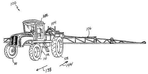
[0019] Referring now to FIG. 1, there is shown a crop sprayer 100. The crop
sprayer 100
includes a cab 102 which houses an operator and a number of controls. The crop
sprayer 100
further includes a chemical tank 104 which stores chemicals, such as
herbicides, pesticides, and
fertilizers. The crop sprayer 100 further includes a boom arm
CA 02593726 2007-06-27
106 which is operable to distribute the chemicals over a wide swath in a
field. In
particular, the chemicals are distributed by nozzles (not shown) spaced along
the boom
arm 106 through which the chemicals are sprayed as the crop sprayer 100 is
propelled. In
alternative embodiments, the storage tank and boom assembly may be located at
different
locations on the crop sprayer such as at the front end of the crop sprayer.
[0020] The
crop sprayer 100 further includes a pair of rear wheels 108 and a pair of
front wheels 110. The rear wheels 108 are driven by a drive train assembly 112
(shown
in FIG. 2) so as to propel the crop sprayer 100 in the desired direction. The
front wheels
110 are operable to steer the crop sprayer 100.
[0021]
Referring now to FIG. 2, there is shown the drive train assembly 112 of the
crop sprayer 100. The drive train assembly 112 includes an engine 114, a
clutch
assembly 116, a transmission 118, a drive shaft 120, a rear differential 122
and a
differential output shaft 124. The clutch assembly 116, the transmission 118,
the drive
shaft 120 and the rear differential 122 and the differential output shaft 124
in this
embodiment are commercially available as a matched set from International
Transmissions LTD of Wrexham, United Kingdom as transmission and axle package
475/45200.
[0022] The
engine 114 may be a diesel engine commercially available from
Cummins Engine Co. Inc., of Columbus, Indiana or Deere & Company of Moline
Illinois. Diesel engines have several advantages including high torque output,
reliability,
and low fuel cost. The engine 114 generates rotational mechanical energy which
is
transferred to the clutch assembly 116 by a crankshaft 126 of the engine 114.
While the
embodiment of FIG. 1 shows the engine 114 mounted at the front end of the crop
sprayer
6
CA 02593726 2007-06-27
100, in alternative embodiments, the engine may be mounted elsewhere on the
crop
sprayer such as at the rear of the crop sprayer.
[0023] The
engine 114 includes a throttle 128. The throttle 128 is operable to control
rotational speed of the crankshaft 126 of the engine 114. In particular, the
throttle 128
controls the amount of air that is advanced into a combustion chamber (not
shown) of the
engine 114. As the amount of air advanced into the combustion chamber is
increased, the
flow of fuel injected into the combustion chamber is similarly increased. By
increasing
the amount of fuel and air combusted in the combustion chamber of the engine
114, the
rotational speed of the crankshaft 126 of the engine 114 is increased. A
signal is sent over
a signal line 130 to control the position the throttle 128 during operation of
the engine
114 so as to control the rotational speed of the crankshaft 126.
[0024] The
clutch assembly 116 is positioned between the engine 114 and the drive
shaft 120. The clutch assembly 116 includes a torque converter which has a
forward
clutch 132 and a reverse clutch 134. The forward clutch 132 is operable to
selectively
couple and decouple the crankshaft 126 of the engine 114 and the drive shaft
120. In
particular, when the forward clutch 132 couples the crankshaft 126 to the
drive shaft 120,
the drive shaft 120 is caused to rotate in a clockwise rotational direction,
as indicated by
the arrow 136. When the drive shaft 120 rotates in the clockwise rotational
direction 136,
the rear wheels 108 are rotated so as to advance the crop sprayer 100 in the
forward
direction indicated by the arrow 138 in FIG. 1. Whereas, when the forward
clutch 132
decouples the crankshaft 126 from the drive shaft 120, the drive shaft 120 is
not caused to
rotate in the direction of the arrow 136. As a result, when the forward clutch
132
7
CA 02593726 2007-06-27
decouples the crankshaft 126 from the drive shaft 120, the engine 114 does not
cause the
rear wheels 108 to rotate so as to advance the crop sprayer 100 in the forward
direction.
[0025] The forward clutch 132 is actuated so as to couple the crankshaft
126 to the
drive shaft 120 in response to an electric signal being received via a signal
line 140. In
particular, when an "on" signal is received by the forward clutch 132 via the
signal line
140, the forward clutch 132 couples the crankshaft 126 to the drive shaft 120
so as to
rotate the drive shaft 120 in the clockwise rotational direction. When an
"off' signal is
received by the forward clutch 132 via the signal line 140, the forward clutch
132
decouples the crankshaft 126 from the drive shaft 120.
[0026] Similarly, the reverse clutch 134 is operable to selectively couple
and
decouple the crankshaft 126 of the engine 114 and the drive shaft 120. In
particular,
when the reverse clutch 134 couples the crankshaft 126 to the drive shaft 120,
the drive
shaft 120 is caused to rotate in a counterclockwise rotational direction, as
indicated by the
arrow 142. When the drive shaft 120 rotates in the counterclockwise rotational
direction,
the rear wheels 108 are rotated so as to advance the crop sprayer 100 in the
reverse
direction as indicated by the arrow 144 in FIG. 1. When the reverse clutch 134
decouples
the crankshaft 126 from the drive shaft 120, the drive shaft 120 is not caused
to rotate in
the counterclockwise rotational direction indicated by the arrow 142. As a
result, when
the reverse clutch 134 decouples the crankshaft 126 from the drive shaft 120,
the engine
114 does not cause the rear wheels 108 to rotate so as to advance the crop
sprayer 100 in
the reverse direction.
[0027] The reverse clutch 134 is actuated so as to couple the crankshaft
126 to the
drive shaft 120 in response to an electric signal being received via a signal
line 146. In
8
CA 02593726 2007-06-27
particular, when an "on" signal is received by the reverse clutch 134 via the
signal line
146, the reverse clutch 134 couples the crankshaft 126 to the drive shaft 120
so as to
rotate the drive shaft 120 in the counterclockwise rotational direction. When
an "off'
signal is received by the reverse clutch 134 via the signal line 146, the
reverse clutch 134
decouples the crankshaft 126 from the drive shaft 120.
[0028] The
transmission 118 is interposed between the clutch assembly 114 and the
drive shaft 120. The transmission 118 in this embodiment is a four speed
transmission
which provides four separate gear ratios between the crankshaft 126 and the
drive shaft
120. The transmission 118 allows the operator to selectively change the gear
ratio
between the clutch assembly 116 and the drive shaft 120. In particular, when
an "up-
shift" signal is received by the transmission 118 via the signal line 148, the
transmission
118 decouples the previously selected gear from the forward clutch 132 and
couples the
gear with the next highest gear ratio to the forward clutch 132 so as to
rotate the drive
shaft 120 at a higher rotational speed but with less torque. When a "down-
shift" signal is
received by the transmission 118 via the signal line 148, the transmission 118
decouples
the previously selected gear from the forward clutch 132 and couples the gear
with the
next lowest gear ratio to the forward clutch 132 so as to rotate the drive
shaft 120 at a
lower rotational speed but with more torque. Thus, the change of gear ratios
allows the
engine 114 to provide torque to the rear wheels 108 for a variety of operating
conditions.
In particular, a gear ratio may be selected that provides high torque at low
crankshaft
speeds whereas a different gear ratio may be selected that provides low torque
at high
crankshaft speeds.
9
CA 02593726 2007-06-27
[0029] The
drive shaft 120 is operatively coupled to the rear differential 122 and the
differential output shaft 124. The rear differential 122 splits the power from
the drive
shaft 120 between each of the rear wheels 108 (shown in FIG. 1) in order to
propel the
crop sprayer 100 in the forward direction and the reverse direction.
[0030] The
signal lines 130, 140, 146 and 148 extend between a microprocessor 150
and the respective component. The microprocessor 150 is part of a crop sprayer
control
assembly 152 which is shown in more detail in FIG. 3. The crop sprayer control
assembly 152 includes a convenience tray 154, an arm rest 156 a joystick 158
and a
control and display panel 160. The control and display panel 160 includes a
display 162
and a number of control switches 164. The display 162 is configured to provide
status
and alarm information for the various systems of the crop sprayer 100 such as
fuel,
hydraulic system parameters, boom condition, chemical tank level, etc. The
control
switches 164 are used to control the various systems.
[0031] The
joystick 158 includes a knob 166 and a shaft 168. A forward gear control
button 170 and a reverse gear control button 172 are located on the side of
the shaft 168
farthest away from the armrest 156. The placement of the forward gear control
button
switch 170 and the reverse gear control button switch 172 allows the buttons
to be
depressed when an operator grasps the shaft 168. Manipulation of the knob 166,
however, is unlikely to result in inadvertent manipulation of the buttons.
[0032] The
joystick 158 is biased toward a neutral position wherein it is aligned with
the axis 174. The joystick may be pivoted forward and backward within a first
plane
through the axis 174 in the directions indicated by the arrows 176 and 178.
The joystick
158 may further be pivoted from one side to the other side within a second
plane through
CA 02593726 2007-06-27
the axis 174 as indicated by the arrows 180 and 182. Movement of the joystick
158 and
manipulation of the forward gear control button switch 170 and the reverse
gear control
button switch 172 is detected by various sensors which are shown in FIG. 4.
[0033] The sensors associated with the joystick 158 include an up-throttle
sensor 184,
a down-throttle sensor 186, an up-shift sensor 188, a down-shift sensor 190, a
forward
engage sensor 192 and a reverse engage sensor 194. The up-throttle sensor 184
is
configured to sense when the joystick 158 is pivoted in the direction of the
arrow 176 and
the down-throttle sensor 186 is configured to sense when the joystick 158 is
pivoted in
the direction of the arrow 178. In this embodiment, the up-throttle sensor 184
and the
down-throttle sensor 186 are configured to generate either a high signal or a
low signal,
depending upon whether or not the joystick 158 is sensed. Thus, the sensors
provide a
digital output. In an alternative embodiment, the sensors may be configured to
be analog
sensors, providing a varying output dependent upon the sensed magnitude of
deflection
of the joystick 158 toward the first or second position. This alternative
configuration is
useful when providing for a varying rate of throttle increase or decrease.
[0034] Continuing with FIG. 4, the down-shift sensor 190 is configured to
sense
when the joystick 158 is pivoted in the direction of the arrow 180 and the up-
shift sensor
188 is configured to sense when the joystick 158 is pivoted in the direction
of the arrow
182. Finally, the forward engage sensor 192 is configured to sense depression
of the
forward gear control button switch 170 and the reverse engage sensor 194 is
configured
to sense depression of the reverse gear control button switch 172.
[0035] Each of the sensors provides a signal to the microprocessor 150 over
one of
the signal lines 196, 198, 200, 202, 204 or 206. The microprocessor 150
evaluates the
11
CA 02593726 2007-06-27
,
incoming signals from the signal lines 196, 198, 200, 202, 204 and 206 along
with status
data from the drive train assembly 112 and, based upon instructions stored in
the memory
208, issues control signals to actuators associated with the various
components of the
drive train assembly 112.
[0036] To move the crop sprayer 100 beginning with the engine 114 turning
the
crankshaft 126 but with no clutch engaged, an operator first manipulates
either the
forward gear control button switch 170 or the reverse gear control button
switch 172.
When the forward gear control button switch 170 is manipulated, the forward
engage
sensor 192 senses the manipulation and generates a signal that is sent to the
microprocessor 150 through the signal line 204. The microprocessor 150 then
determines
that the forward clutch 132 is not engaged based upon a signal from the signal
line 140
and that the reverse clutch 134 is not engaged based upon a signal from the
signal line
146. Therefore, based upon instructions stored in the memory 208, the
microprocessor
150 generates a control signal which is sent via the signal line 140
controlling an actuator
so as to engage the forward clutch 132 and the crankshaft 126. Thus, rotation
of the
crankshaft 126 is passed through the forward clutch 132 to the drive shaft
120, causing
the drive shaft 120 to rotate in the direction of the arrow 136 (FIG. 2) so as
to propel the
crop sprayer 100 in the forward direction indicated by the arrow 138 of FIG.
1.
[0037] In the event the forward clutch 132 is engaged when the
microprocessor 150
receives a signal through the signal line 204, the instructions stored in the
memory 208 in
this embodiment, when executed by the microprocessor 150 will cause a signal
to be sent
to the actuator for the forward clutch 132 causing the forward clutch 132 to
be
disengaged from the crankshaft 126. Similarly, if the reverse clutch 134 is
engaged when
12
CA 02593726 2007-06-27
the microprocessor 150 receives a signal through the signal line 204, the
instructions
stored in the memory 208 in this embodiment, when executed by the
microprocessor 150
will cause a signal to be sent to the actuator for the reverse clutch 134
causing the reverse
clutch 134 to be disengaged from the crankshaft 126.
[0038] If the reverse gear control button switch 172 is manipulated instead
of the
forward gear control button switch 170, the reverse engage sensor 194 senses
the
manipulation and generates a signal that is sent to the microprocessor 150
through the
signal line 206. The microprocessor 150 then determines that the forward
clutch 132 is
not engaged based upon a signal from the signal line 140 and that the reverse
clutch 134
is not engaged based upon a signal from the signal line 146. Therefore, based
upon
instructions stored in the memory 208, the microprocessor 150 generates a
control signal
which is sent via the signal line 146 controlling an actuator so as to engage
the reverse
clutch 134 to the crankshaft 126. Thus, rotation of the crankshaft 126 is
passed through
the reverse clutch 134 to the drive shaft 120, causing the drive shaft 120 to
rotate in the
direction of the arrow 142 (FIG. 2) so as to propel the crop sprayer 100 in
the rearward
direction indicated by the arrow 144 of FIG. 1.
[0039] In the event the forward clutch 132 is engaged when the
microprocessor 150
receives a signal through the signal line 206, the instructions stored in the
memory 208 in
this embodiment, when executed by the microprocessor 150 will cause a signal
to be sent
to the actuator for the forward clutch 132 causing the forward clutch 132 to
be
disengaged from the crankshaft 126. Similarly, if the reverse clutch 134 is
engaged when
the microprocessor 150 receives a signal through the signal line 206, the
instructions
stored in the memory 208 in this embodiment, when executed by the
microprocessor 150
13
CA 02593726 2007-06-27
will cause a signal to be sent to the actuator for the reverse clutch 134
causing the reverse
clutch 134 to be disengaged from the crankshaft 126.
[0040] Additional data may be considered by the microprocessor 150 prior to
engaging or disengaging a clutch. By way of example, the speed and direction
of rotation
of the drive shaft 120 may be provided to the microprocessor 150. Accordingly,
an
instruction may be stored in the memory 208 the execution of which only allows
a clutch
to be engaged if the drive shaft 120 is not rotating. Alternatively, a small
amount of
rotation in the direction opposite to the clutch to be engaged may be allowed.
This
reduces wear on the system in the event one of the gear control button
switches is
inadvertently depressed twice. In one embodiment, a clutch is allowed to be
engaged so
long as the drive shaft 120 is rotating in the opposite direction at a speed
corresponding to
about 3 miles per hour.
100411 Deflection of the joystick 158 in the direction of the arrow 182 of
FIG. 3 is
sensed by the up-shift sensor 188 and a signal is sent to the microprocessor
150 over the
signal line 200. The microprocessor 150 then determines the status of the
forward clutch
132, the reverse clutch 134 and the transmission 118 using one or more inputs
from the
signal lines 140, 146 and 148, respectively. If the reverse clutch 134 is
engaged, then the
microprocessor 150 ignores the signal since, in this embodiment, there is only
a single
reverse gear. Likewise, if the forward clutch 132 is not engaged, the signal
is ignored.
Alternatively, a warning signal may be sent to the display 162. In the event
more than
one reverse gear is available, then the microprocessor will command the drive
train
components 112 in a manner similar to the following process which is performed
when
the forward clutch 132 is engaged.
14
CA 02593726 2007-06-27
[0042] If the microprocessor 150 determines that the forward clutch 132 is
engaged,
the actual gear in the transmission 118 that is engaged to the crankshaft 126
through the
forward clutch 132 is determined. If the engaged gear in the transmission 118
is the gear
with the highest gear ratio then the signal from the up-shift sensor 188 is
ignored. If the
gear that is engaged in the transmission 118 is not the gear with the highest
gear ratio,
then the microprocessor 150, based upon stored instructions in the memory 208,
sends a
signal over the line 140 so as to control the actuator for the forward clutch
132 to
disengage the forward clutch 132 from the crankshaft 126. Then, a signal is
sent over the
signal line 148 to the transmission 118 selecting the gear with the next
highest gear ratio
compared to the previously engaged gear. Finally, the microprocessor 150 sends
a signal
over the line 140 so as to control the actuator for the forward clutch 132 to
engage the
forward clutch 132 with the crankshaft 126. Thus, rotational movement of the
crankshaft
126 is passed through a gear in the transmission 118 with a higher gear ratio.
[0043] Deflection of the joystick 158 in the direction of the arrow 180 of
FIG. 3 is
sensed by the down-shift sensor 190 and a signal is sent to the microprocessor
150 over
the signal line 202. The microprocessor 150 then determines the status of the
forward
clutch 132, the reverse clutch 134 and the transmission 118 using signals from
the signal
lines 140, 146 and 148, respectively. If the reverse clutch 134 is engaged or
the forward
clutch 132 is not engaged, the signal is ignored or a warning signal may be
generated.
[0044] If the microprocessor 150 determines that the forward clutch 132 is
engaged,
the actual gear in the transmission 118 that is engaged to the crankshaft 126
through the
forward clutch 132 is determined. If the engaged gear in the transmission 118
is the gear
with the lowest gear ratio then the signal from the down-shift sensor 190 is
ignored. If
CA 02593726 2007-06-27
the gear that is engaged in the transmission 118 is not the gear with the
lowest gear ratio,
then the microprocessor 150, based upon stored instructions in the memory 208,
sends a
signal over the line 140 so as to control the actuator for the forward clutch
132 to
disengage the forward clutch 132 from the crankshaft 126. Then, a signal is
sent over the
signal line 148 to the transmission 118 selecting the gear with the next
lowest gear ratio
compared to the previously engaged gear. Finally, the microprocessor 150 sends
a signal
over the line 140 so as to control the actuator for the forward clutch 132 to
engage the
forward clutch 132 with the crankshaft 126. Thus, rotational movement of the
crankshaft
126 is passed through a gear in the transmission 118 with a lower gear ratio.
[0045] If desired, the microprocessor 150 may be configured to further
process
available data prior to actually shifting gears in the manner described above.
By way of
example, a signal corresponding to the current rotational speed and direction
of the drive
shaft 120 may be provided to the microprocessor 150. Based upon the rotational
speed of
the drive shaft 120, the microprocessor may delay the actual gear shift,
particularly when
up-shifting, until the rotational speed of the drive shaft 120 has been
increased to a
predetermined level. This reduces the amount of shock to the system because of
the
change in torque resulting from the higher gear ratio. Additional inputs, such
as current
torque on various parts of the system, may also be used.
[0046] Deflection of the joystick 158 in the direction of the arrow 176 of
FIG. 3 is
sensed by the up-throttle sensor 184 and a signal is sent to the
microprocessor 150 over
the signal line 196. The microprocessor 150 then determines the status of the
throttle 128
using a signal from the signal line 130. If the throttle 128 is fully open or
at the upper
limit, then the signal is ignored or a warning signal may be generated.
16
CA 02593726 2007-06-27
[0047) If the
microprocessor 150 determines that the throttle 128 is not fully opened,
then the microprocessor 150, based upon stored instructions in the memory 208,
sends a
signal over the line 130 so as to control the actuator for the throttle 128 to
control the
throttle 128 toward the full open position at a predetermined rate of opening.
The
microprocessor 150 controls the throttle 128 so as to continue opening for so
long as the
up-throttle sensor 184 senses that the joystick 158 is deflected. As the
throttle 128 is
opened, the amount of fuel introduced into the combustion chambers of the
engine 114 is
increased causing an increase in the rotational speed of the crankshaft 126.
Thus, the
rotation of the driveshaft 120 is increased, causing the crop sprayer 100 to
accelerate.
100481 Once
the desired speed is achieved, the operator releases the joystick 158
which is biased toward the neutral position. As the joystick 158 moves to the
neutral
position, the up-throttle sensor 184 will lose the ability to sense the
joystick 158 and the
signal is removed from the signal line 196. The microprocessor 150 then
removes the
signal from the signal line 130 and the throttle 128 is maintained at the
resulting position.
100491
Alternative instructions may be stored in the memory 208 for execution by the
microprocessor 150. By way of example, but not of limitation, the
microprocessor may
be configured to modify a speed set point based upon the deflection of the
joystick 158.
In one such embodiment, a set point speed is indicated on the display 162. In
response to
a deflection of the joystick 158, the set point speed is increased. When the
desired set
point speed is displayed, the operator releases the joystick.
Meantime, the
microprocessor determines a discrepancy between the set point speed and the
actual
speed, and controls the throttle as necessary to increase the actual speed to
the set point
speed.
17
CA 02593726 2007-06-27
[0050] Deflection of the joystick 158 in the direction of the arrow 178 of
FIG. 3 is
sensed by the down-throttle sensor 186 and a signal is sent to the
microprocessor 150
over the signal line 198. The microprocessor 150 then determines the status of
the
throttle 128 using a signal from the signal line 130. If the throttle 128 is
at its lower
limit, then the signal is ignored or a warning signal may be generated.
[00511 If the microprocessor 150 determines that the throttle 128 is not at
the lower
limit, then the microprocessor 150, based upon stored instructions in the
memory 208,
sends a signal over the line 130 so as to control the actuator for the
throttle 128 to control
the throttle toward the full shut position at a predetermined rate of closing.
The
microprocessor 150 controls the throttle 128 so as to continue closing for so
long as the
down-throttle sensor 186 senses that the joystick 158 is deflected. As the
throttle 128 is
closed, the amount of fuel introduced into the combustion chambers of the
engine 114 is
decreased causing a decrease in the rotational speed of the crankshaft 126.
Thus, the
rotation of the driveshaft 120 is decreased, causing the crop sprayer 100 to
decelerate.
[00521 Once the desired speed is achieved, the operator releases the
joystick 158
which is biased toward the neutral position. As the joystick 158 moves to the
neutral
position, the down-throttle sensor 186 will lose the ability to sense the
joystick 158 and
the signal is removed from the signal line 198. The microprocessor 150 then
removes the
signal from the signal line 130 and the throttle 128 is maintained at the
resulting position.
[0053] While the invention has been illustrated and described in detail in
the
drawings and foregoing description, the same should be considered as
illustrative and not
restrictive in character. It is understood that only the preferred embodiments
have been
18
CA 02593726 2014-01-03
presented and that all changes, modifications and further applications that
come within
the scope of the invention are desired to be protected.
19