Note: Descriptions are shown in the official language in which they were submitted.
CA 02593814 2007-07-04
WO 2006/073811 PCT/US2005/046203
FLUORESCENCE DETECTION SYSTEM
CROSS-REFERENCE TO RELATED APPLICATIONS
[001] Not applicable.
BACKGROUND OF THE INVENTION
1. The Field of the Invention
[002] The present invention is directed to a methods and apparatus for
exciting
fluorescent material and detecting fluorescence in a sample.
2. The Relevant Technology
[0031 Various optical detection systems have been developed for use in
qualitative and quantitative measurements: One common system involves the use
of
fluorescent compounds as labels that are associated with targets, such as the
reaction
products of polymerase chain reaction (PCR) amplification.
[004] Numerous chemical compounds have been identified that exhibit
fluorescence when illuminated with light at a suitable excitation frequency.
For
example, fluorescein is excited by light at a wavelength of about 490 nm, and
emits
light at a wavelength of about 520 nm. The gap between the excitation and
emission
wavelengths allows observation and measurement of fluorescence either
qualitatively
or quantitatively by reference to the emission wavelength.
[005] One conventional fluorescent reading system passes a light through a
bandpass filter, which transmits light at the excitation wavelength, through a
sample,
through a second bandpass filter that transmits light at the emission
wavelength, and
to a detector. In this classical system, multiple samples are shuttled into
place for
sequential readings, such as through use of a carousel. In order to speed up
the
process, alternative stepping systems have been developed (for example, see
U.S.
Patent No. 6,015,674) or multiple light emitting diodes have been provided
together
with a network of optical f bers to perform several tests simultaneously (see,
for
example, U.S. Patent No. 6,597,450). Although these types of systems are
useful,
they produce opto-mecha ~,zical noise which reduces sensitivity of the system,
and they
require a significant amount of time to measure all of the samples due to the
time it
takes to move the optical system head to the samples, or the samples to the
head.
1
SUBSTITUTE SHEET (RULE 26)
CA 02593814 2007-07-04
WO 2006/073811 PCT/US2005/046203
Fiber optic systems further suffer from the attenuation of a signal associated
with the
use of fiber optics, which also reduces sensitivity.
BRIEF SIJIVIlVIARY OF THE INVENTION
[006] The present invention provides apparatus and methods for exciting and
35 detecting fluorescence in samples.
[007] In one embodiment, a sample holder for holding a plurality of samples is
provided together with an optical manifold having a separate excitation source
and a
separate photo receiver for each of the plurality of samples.
[008] In another embodiment, the optical manifold contains only an excitation
40 source, and the photo receiver is associated with the sample holder.
[009] In another embodiment, the optical manifold contains only a photo
receiver, and an excitation source is associated with the sample holder.
[010] In another embodiment, no optical manifold is provided, and both the
excitation source and the photo receiver are located in the sample holder.
45 [011] The present invention permits rapid excitation and measurement of
fluorescence without the use of moving parts and without any opto-mechanical
or
electronic disturbance. It exhibits an exceptional signal to noise ratio,
which permits
it to differentiate between very low level differences in fluorescence.
[012] These and other features of the present invention will become more fully
50 apparent from the following description and appended claims, or may be
learned by
the practice of the invention as set forth hereinafter.
2
CA 02593814 2007-07-04
WO 2006/073811 PCT/US2005/046203
BRIEF DESCRIPTION OF THE DR.AWINGS
[013] To further clarify the above and other advantages and features of the
present invention, a more particular description of the invention will be
rendered by
55 reference to specific embodiments thereof which are illustrated in the
appended
drawings. It is appreciated that these drawings depict only typical
embodiments of
the invention and are therefore not to be considered limiting of its scope.
The
invention will be described and explained with additional specificity and
detail
through the use of the accompanying drawings in which:
60 [014] Figure 1 is a schematic representation of an embodiment including an
optical manifold, sample holder and photo receiver.
[015] Figure 2 is a schematic representation of another embodiment including
an
optical manifold, sample holder and photo receiver.
[016] Figure 3 is a schematic representation of another embodiment including
an
65 optical manifold, sample holder and photo receiver.
[017] Figure 4 is a schematic representation of another embodiment including
an
optical manifold, sample holder and photo receiver.
[018] Figure 5 depicts a sample holder having an excitation source and photo
receiver incorporated therein.
70 [019] Figure 6 depicts a sample holder having the configuration of a
conventional 96 well plate, and an optical manifold having an excitation
source and
photo receiver associated with each of the 96 sainple holders.
[020] Figure 7 is a schematic depicting an embodiment of a controller in
connection with an optical manifold, sample holder and photo receiver.
75 [021] Figure 8 is a schematic depicting another embodiment of a controller
in
connection with an optical manifold, sample holder and photo receiver.
[022] Figure 9 is a schematic representation of an alternative embodiment of a
detection system in accordance with the present invention.
[023] Figure 10 depicts fluorescent luminosity during the first seven cycles
of
80 PCR.
3
CA 02593814 2007-07-04
WO 2006/073811 PCT/US2005/046203
[024] Figure 11 depicts fluorescent luminosity during the first seven cycles
of a
PCR thermocycler in the absence of DNA amplification.
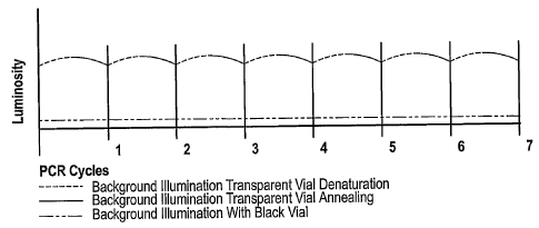
[025] Figure 12 shows fluorescent luminosity of noise during the first seven
cycles of PCR using a conventional sample vial versus a black opaque PCR vial.
4
CA 02593814 2007-07-04
WO 2006/073811 PCT/US2005/046203
85 DETAILED DESCRIPTION OF THE PREFERRED EMBODIMENTS
[026] The present invention provides an optical system useful for measurement
of small amounts of fluorescence in single samples or an array of samples,
such as in
a conventional 96 well plate. A feature of the invention is the lack of
mechanical
movement or sharing of optical components during excitation/emission,
resulting in
90 very rapid readings, and avoiding loss of sensitivity due to opto-
mechanical
movements.
[027] An einbodiment of the present invention is depicted in Figure 1, which
illustrates one configuration for practicing the present invention. Figure 1
illustrates
the positioning of an optical manifold 20 in proximity to a sample vial 22
held by a
95 sample well support 38A. Sample vial 22 contains a sainple 24 which may
contain a
substance to be detected qualitatively or quantitatively using fluorescence.
[028] Optical manifold 20 is provided with an excitation source 26 that
generates
light at the excitation frequency. An excitation bandpass filter 28 passes
light at the
excitation frequency.
10o [029] Excitation source 26 and excitation bandpass filter 28 are arranged
so that
light at the excitation frequency will strike sample 24. An emission bandpass
filter 30
is located over sample 24 so that it will be struck by emissions from
fluorescent
material in the sample. A suitable photo receiver 32 receives light passing
through
emission bandpass filter 30.
105 [030] Although other configurations may be used, it is presently preferred
that
the excitation source and the photo receiver be set off-axis so as to form a
ray trace
which is primarily coincidental to targeted liquid in a PCR well. An offset of
7
degrees has been found suitable. Of course, those of ordinary skill will
appreciate in
view of the teachings herein that other configurations are possible.
110 [031] Figure 2 illustrates a different approach for holding a sample.
Unlike
Figure 1, which shows the use of a sample vial, Figure 2 shows the use of a
dimple 34
which can hold a suitable volume of sample. It will be apparent to one of
ordinary
skill in view of these teachings that other structures may be used in place of
a dimple.
CA 02593814 2007-07-04
WO 2006/073811 PCT/US2005/046203
[032] Figure 3 illustrates an alternative geometric arrangement of the
115 components of Figure 1. In Figure 3, manifold 36A supports a photo
receiver 32 and
a bandpass filter 32 over sample wel122, and sample well support 38B is fitted
with
excitation source 26 and excitation bandpass filter 28.
[033] Figure 4 is similar to Figure 3, but the excitation source and
excitation
bandpass filter are located in manifold 36B, and emission bandpass filter 30
and photo
120 receiver 32 are located in sample well support 38C.
[034] Figure 5 depicts an alternative embodiment of the invention omits the
use
of a separate optical manifold. Figure 5 shows one manner of incorporating an
excitation source 26 and a photo receiver 32 in sample well support 38D. As
with
other embodiments, the embodiment of Figure 5 may also include excitation
bandpass
125 filter 26 and emission bandpass filter 30. Because of the cost of
incorporating these
components in the sample holder, it is preferred that the sample holder
assembly be
reusable, and to effect easy disposal of samples, it is preferred that the
sample holder
be configured to accept sample vials 22 rather than dimples or other non-
disposable
sample receptacle. In Figure 5, the excitation source and photo receiver are
depicted
130 in-line with one another. One or ordinary skill will appreciate in view of
the teachings
herein that other configurations would also provide the benefits of the
invention.
[035] Suitable excitation sources include an LED and a laser diode. It is
presently preferred that the excitation source provide high luminosity,
preferably in
the range of about 7000 to 25,000 millicandle power. It is also preferred that
the
135 excitation source have a dispersion beam less than about 20 degrees so as
to provide
efficient emission without the need for condensing optics.
[036] Suitable photo receivers include cadmium sulfide photo resistors, PIN
diodes, photo-transistors, or other devices capable of detecting light at the
excitation
frequency.
140 [037] It will also be appreciated by one of ordinary skill in the art that
there may
be no need for a bandpass filter, or that other structures may be provided in
place of a
bandpass filter to remove unwanted light or if the illumination source is
monochromatic at the desired wavelength.
6
CA 02593814 2007-07-04
WO 2006/073811 PCT/US2005/046203
[038] It would be possible to add further structures, such as focusing optics,
but
145 it has been found in the configurations described above that no separate
optics are
typically necessary.
[039] Figures 1- 5 show various optical component configurations associated
with a single sample. One of the advantages of the present invention is the
ability to
deal with a large number of samples simultaneously. Figure 6 illustrates the
use of
150 the basic configuration of Figure 1 for each sample well of a conventional
96 well
plate 40. This is accomplished in Figure 6 by providing a manifold 42 fitted
with 96
separate combinations of excitation source 26, excitation bandpass filter 28,
emission
bandpass filter 30 and photo receiver 32, which are associated with the 96
sample
wells. The configuration of Figure 6 is suitable for use in connection with
PCR or
155 ELISA readers, or other multiple sample requirements. The configuration of
Figure 6
is capable of reading eacli of the 96 wells of a conventional 96 well plate in
just a few
milliseconds without any opto-mechanical or electronic disturbance. The
manifold is
very rugged and highly reliable, making it suitable for portable laboratory
equipment.
[040] Figure 7 depicts schematically an embodiment of a controller system. DC
160 power supply 44 is provided to power the plurality of excitation sources
26. One or
more relays 46 are provided to operate each of a plurality of excitation
sources 26. A
computer or programmable logic controller (not shown), or other controller,
turn the
excitation sources on and off as desired. A single relay 46 may be used in
some
configurations to activate all of the excitation sources simultaneously, or
separate
165 relays may be used for each of the excitation sources.
[041] A schematic representation of the optical excitation components is also
shown in Figure 7 using the same reference numerals assigned above with
respect to
various components: excitation sources 26 are shown in conjunction with
excitation
bandpass filters 28 so as to direct excitation light into sample vials 22.
Emission
17o bandpass filters 30 and photo receivers 32 receive fluorescent emission
light from the
samples. Data from the photo receivers is preferably passed to respective
amplifiers
48, which amplify the signals from the corresponding photo receiver. It is
contemplated that a typical photo receiver will produce an analog signal, and
in such a
7
CA 02593814 2007-07-04
WO 2006/073811 PCT/US2005/046203
case it is preferred that each amplifier have an adjustable gain so that a
calibration
175 may be performed to insure that each photo receiver/amplifier coinbination
provide
comparable data for subsequent analysis, thereby allowing for differences that
may
exist among system components under calibration conditions.
[042] The signals from amplifiers 48 are sent to a inultiplexing device 50,
which
operates in coordination with clocking device 52 to control switching between
the
180 plurality of inputs from the various amplifiers, and sends a signal to an
analog input
54 of a computer, wherein the term "computer" is used broadly to include use
of a
programmable logic controller or other structure capable of performing this
function.
[043] Figure 8 depicts another embodiment of a controller system, illustrating
that various controller systems may be advantageously used in conjunction with
the
185 optical components described above. Figure 8 shows an analog output 56
from a
computer that is connected to an amplifier 58 used to drive excitation sources
26.
LEDs used as excitation sources exliibit a brightness that is proportional to
the applied
voltage. This allows the computer or controller to control the intensity of
LEDs used
as excitation sources in response to needed sensitivity, or alternatively to
account for
19o calibration requirements. One method of calibration is to use a
standardized
fluorescent material in a known concentration and calibrating each channel
until each
channel produces the same measurement output. Various approaches can be used
to
perform this calibration: for example, one could separately adjust the gain of
the
amplifiers, or the intensity of the excitation source, or an adjustment may be
handled
195 at the computer.
[044] In the embodiment of Figure 8, it is preferred that the photo receivers
be of
the type typically referred to as "avalanche" receivers, which refers to
receivers which
change from a fully "off' state to a fully "on" state when the emitted
luminosity of
the fluorescing material reaches a certain level. The applied voltage required
to cause
200 the photo receiver to change to an "on" state can be used as a measure of
the amount
of fluorescence. For example, if a relatively large voltage (high intensity
excitation
source) is required to move the photo receptor to the "on" state, then only a
small
amount of fluorescence is occurring in the sample. The converse is true: if
only a
8
CA 02593814 2007-07-04
WO 2006/073811 PCT/US2005/046203
relatively small voltage results in activation of the photo receiver, this is
an indication
205 that a lot of fluorescence is occurring. Measurement of the voltage
required to cause
the photo receiver to change to the "on" state allows for quantitative
determination of
the amount of fluorescent material in the sample.
[045] Non-linear amplifiers 58 may be used advantageously to amplify the
signals from photo receivers 32. It is preferred that amplifiers 58 have
variable gain
210 adjustment ability to allow them to be more useful in a variety of
circumstances. Shift
register 60 is useful for monitoring one of the plurality of incoming signals
to input 62
of the computer or controller. A digital "clock" signal 64 may be used in this
configuration to cause shift register 60 to switch between the plurality of
inputs from
the various photo receivers so that all of the channels are read by the
computer.
215 [046] Figure 9 depicts schematically an embodiment of a higli-gain low-
noise
electro-optical system. This system is shown with two sample vials 22,
together with
associated optical components, although it should be understood that a useful
system
might include only a single sample, or many samples.
[047] Excitation sources 26 and excitation bandpass filters 28 are placed so
as to
220 direct excitation emissions onto a sanzple within sample vials 22.
Emission bandpass
filters 30 are shown in combination with photo resistors 70, which are
sensitive photo
resistors capable of creating high electronic gain from minute fluorescent
photon
emission sources. When using fluorescein as a fluorescent material, the
preferred
photo resistor is of a high impedance cadmium sulfide type which demonstrates
good
225 photo response for the fluorescein emission wavelength.
[048] Associated with photo resistor 70 is a high impedence-dropping resistor
72, the combination of which allows a relatively large electrical signal to
develop
even in the presence of low light levels. Inclusion of filter capacitors 74
dampen
electronic radio frequency (RF) interference by providing a shunting pathway
to
230 preclude amplification of RF electrical noise. Linear anlplifiers 76 are
provided with
gain adjustment so as to permit the balancing of the plurality of electro-
optical
circuits with one another.
9
CA 02593814 2007-07-04
WO 2006/073811 PCT/US2005/046203
[049] The electro-optical system of Figure 9 is provided with a DC power
supply
44 and a gating relay 78 controlled by a computer. The outputs of linear
amplifiers 76
235 advantageously pass to an analog gating multiplexer 80, which in turn is
connected to
a digital gate signal 82 a.nd an analog input 84 to a computer. The linear
amplifiers
also provide impedance matching with the analog gating inultiplexer 80. The
analog
multiplexer provides a means whereby all of the outputs of the plurality of
linear
amplifier outputs can be sampled and read every few milliseconds by the
managing
240 computer, which is preferably a programmable logic controller for use with
the
embodiment of Figure 9.
[050] It has been discovered that use of a black opaque ultra low fluorescent
sample vial allows for detection of lower level fluorescent emissions than a
conventional clear sample vial. Without wishing to be bound by theory, it is
believed
245 that minute thermally induced changes in conventional clear vial walls
contribute to
variations in background fluorescence. Vials commonly found in the laboratory
which
are lightly pigmented for purposes of identification are also often highly
fluorescent,
which has been discovered to add noise and diminish sensitivity.
[051] The embodiment of Figure 9 provides similar photo sensitivity to that of
a
250 photo multiplier tube (PMT). It can sense small changes in very low light
levels, and
requires no mechanical stepping mechanism to read 96 sample vials containing
fluorescent material in less than one second. Another advantage of this
embodiment
is that each photo resistor occupies a space of only about 9 mm by 9 mm, which
is
only a fraction of amount of space required for a PMT. Yet another advantage
of this
255 embodiment is that it uses low voltage, whereas a PMT typically requires
voltages of
1000 volts or more.
[052] Another advantage of the embodiment of Figure 9 is the ability to use it
in
connection with monitoring of amplification using the polymerase chain
reaction
(PCR), by monitoring differences in fluorescence very early in the PCR
process. In
260 conventional systems, the first five PCR cycles are often considered to be
the "zero"
baseline because DNA growth cannot be successfully detected during these
cycles. It
is not until the 20th cycle before DNA amplification can be reliably observed
in
CA 02593814 2007-07-04
WO 2006/073811 PCT/US2005/046203
conventional systems due to noise. It has been found that the embodiment of
Figure 9
can detect positive DNA amplification between cycle 5 and cycle 7. For some
265 applications, early detection of DNA amplification allows the use of fewer
thermal
cycles.
[053] Figure 10 illustrates the luminescent output of a fluorescent probe
which is
at its highest level when DNA is double stranded, and its lowest level when
the DNA
is single stranded. The steady growth of double stranded DNA is indicated by
the ever
270 increasing illumination peaks at the end of the annealing phases. During
the
denaturation stage, the luminosity temporarily declines as all of the double
stranded
DNA is converted back to single stranded DNA. The luminosity returns and
reaches
an ever higher level as the successive annealing stages occur and more DNA is
produced. This system allows for a definitive view of the rates of reaction of
the
275 biochemistry in the PCR process. Knowledge of the rate of reaction in the
PCR
process is very useful in prediction and optimization of the process.
[054] More complex observations are also possible. For example, logarithmic
curves of declining photo luminescence occurs during the denaturation portion
of a
PCR cycle. Reciprocally, a logarithmically increasing fluorescence is detected
as the
280 annealing takes place.
[055] The sensitivity of the present invention may not be fully useful with
traditional thermocyclers used in the practice of PCR, but the present
invention is
particularly useful in combination with the novel thermocyclers disclosed in
copending patent application number 10/991,746, entitled "Rapid Thermocycler,"
285 filed on November 18, 2004, and having a common assignee with the present
application, which application is incorporated herein in its entirety. This is
because
the transition times of conventional thermocyclers between different phases
are
typically about 45 seconds, and these extended transition times tend to
obliterate or
distort the observed curves. For better results, the transition time between
phases
290 should be reduced, preferably to only a few seconds. Conventional
thermocyclers also
suffer from significant thermal noise, whicli is reduced in the thermocyclers
of the
"Rapid Thermocycler" application.
11
CA 02593814 2007-07-04
WO 2006/073811 PCT/US2005/046203
[056] Figure 11 illustrates PCR readings when no amplification takes place.
The
slope of the peaks is ever descending due to inherent decay of the fluorescent
probe
295 when exposed to constant illumination. This same decay is observed when
exposing
chemically pure fluorescein free of attachment to a probe. The decay rate is
observed
to be about 0.02% per second of continuous exposure to a strong source of
excitation
light. The fluorescent luminosity decay which is observed in this invention
operates
in opposition to growth in luminosity due to increases in DNA. This phenomenon
300 serves to widen the differential luminescence between growth and no growth
of DNA.
During cycle one through cycle three the decay of the fluorescent signal may
decrease
the luminosity of the sample greater than the increase of luminosity
associated with
the growth in DNA. However in cycles 4 and above, the increase in luminosity
associated with the growth in DNA will push the overall luminosity upward.
After
305 that, the binary nature of the DNA growth overwhehns the fluorescent
signal decay.
[057] Fig 12 compares the use of transparent thermoplastic vials and black
opaque vials. The background signal of conventional clear sample vials can be
almost
totally eliminated by using a black opaque vial. When the background
fluorescence is
held to a minimum, the electro-optical signal can be more highly amplified as
the
310 signal-to-noise ratio is improved. Ultra-low fluorescent vials are very
helpful in
reducing noise for applications requiring detection of low level fluorescent
changes.
[058] Low level fluorescent detection is useful when qualitative PCR detection
of potentially harmful biological agents is time sensitive. The ainount of
time
required for statistically certain detection is reduced from nearly an hour or
more
315 when using conventional fluorescent PCR detection systeins to 15 minutes
or less
when using the present invention in combination with the rapid thermocycler
described in the copending application cited above.
[059] The present invention provides an unusually useful and rapid fluorescent
optical reader system, capable of reading every well of a 96 well plate in
just a few
320 milliseconds, without any moving parts, and without any opto-mechanical or
electronic disturbance. The system provides an outstanding signal to noise
ratio,
which permits it to be used to differentiate between very low level
differences in
12
CA 02593814 2007-07-04
WO 2006/073811 PCT/US2005/046203
fluorescence. The inventive system is quite compact and sufficiently rugged to
make
it practical not only in laboratory applications but also in portable
equipment intended
325 for use in the field.
[060] The present invention may be embodied in other specific forms without
departing from its spirit or essential characteristics. The described
embodiments are
to be considered in all respects only as illustrative and not restrictive. The
scope of
the invention is, therefore, indicated by the appended claims rather than by
the
330 foregoing description. All changes which come within the meaning and range
of
equivalency of the claims are to be embraced within their scope.
13