Note: Descriptions are shown in the official language in which they were submitted.
CA 02593941 2007-07-18
RING BINDER MECHANISM
CROSS-REFERENCE
[0001] This application is a continuation-in-part of U.S.
Patent Application No. 11/190,328, filed July 27, 2005, which
claims priority to provisional Patent Application No. 60/664,125,
filed March 22, 2005.
BACKGROUND
[0002] This invention relates generally to ring binder
mechanisms (broadly referred to herein as a ring mechanism) for
retaining loose-leaf pages, and in particular to such a ring
mechanism capable of opening and closing mating ring members and
locking the ring members when closed.
[0003] A ring mechanism is typically used to retain loose-
leaf pages, such as hole-punched pages, in a file or notebook.
Ring mechanisms commonly have mating ring members that may be
selectively opened to add or remove pages, or closed together to
retain pages while allowing the pages to be moved along the ring
members. The ring members mount on two adjacent (e.g., side-by-
side) hinge plates that join together along a hinge line to form
a pivot axis about which the plates may pivot. An elongate,
resilient housing loosely supports the hinge plates within the
housing and holds the hinge plates together so they may pivot
relative to the housing.
[0004] The housing is slightly narrower than the joined
hinge plates when the hinge plates are in a coplanar position
(180 ). In this manner, as the hinge plates pivot through their
coplanar position, they deform the resilient housing and cause a
spring force in the housing that urges the hinge plates to pivot
away from the coplanar position, either opening or closing the
ring members. Thus, when the ring members are closed the spring
force resists hinge plate movement and clamps the ring members
together. Similarly, when the ring members are open, the spring
force holds them apart. An operator may typically overcome this
1
CA 02593941 2007-07-18
force by manually pulling the ring members apart or pushing them
together. Levers or other actuating systems may also be provided
on one or both ends of the housing for moving the ring members
between the open and closed positions. In some ring mechanisms,
however, when the ring members are closed they do not positively
lock in their closed position. As a result, if the mechanism is
accidentally dropped, the ring members may unintentionally open.
[0005] To this end, some ring mechanisms have been modified
to include locking structure to block the hinge plates from
pivoting when the ring members are closed. The locking structure
positively locks the closed ring members together, preventing
them from unintentionally opening if the ring mechanism is
accidentally dropped. The locking structure also allows the
housing spring force to be reduced because the strong spring
force is not required to clamp the closed ring members together.
Thus, less operator force is required to open and close the ring
members than in traditional ring mechanisms.
[0006] Some of these ring mechanisms incorporate the
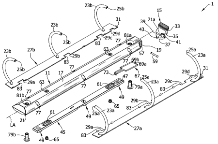
locking structure onto a control slide connected to the lever.
The lever moves the control slide (and its locking structure) to
either block the pivoting movement of the hinge plates or allow
it. However, an operator must positively move the lever after
closing the ring members to position the locking structure to
block the hinge plates and lock the ring members closed. Failure
to do this could allow the hinge plates to inadvertently pivot
and open the ring members, especially if the mechanisms are
accidentally dropped.
[0007] Other locking ring mechanisms use springs to move
the locking structure into position blocking the hinge plates
when the ring members close. Examples are shown in co-owned U.S.
Pat. Appl. Nos. 10/870,801 (Cheng et al.), 10/905,606 (Cheng),
and 11/027,550 (Cheng). These mechanisms employ separate springs
to help lock the mechanisms.
2
CA 02593941 2007-07-18
[0008] Accordingly, there is a need for a simple ring
binder mechanism that readily locks ring members together when
the mechanism is closed without requiring additional spring
components to do so.
[0009] Moreover, the configuration of some locking ring
binder mechanisms is such that the control slide can bind when
the mechanism is being operated, which makes it difficult to open
the rings of the mechanism. Accordingly, there is also a need
for ring binder mechanisms in which such binding of the control
slide is avoided.
SUMMARY
[0010] In one embodiment, a ring mechanism for holding
loose-leaf pages generally comprises a housing and at least one
ring for holding the loose-leaf pages. Each ring comprises a
first ring member and a second ring member, with the ring members
being configurable between a closed position and an open
position. In the closed position the ring members form a
substantially continuous closed loop for allowing loose-leaf
pages retained by the ring to be moved along the ring from one
ring member to the other, and in the open position the two ring
members form a discontinuous, open loop for adding or removing
loose-leaf pages from the ring. A hinge mechanism is operatively
connected to the ring members for configuring the ring members
between their open and closed position. The hinge mechanism
generally comprises a pair of elongate hinge plates supported
within the housing for pivoting movement relative to the housing
between a first hinge plate position corresponding to the closed
position of the ring members and a second hinge plate position
corresponding to the open position of the ring members. Each of
the hinge plates has a free end and a line weakness formed
therein proximate the free end to facilitate bending of the hinge
plate. An actuator is moveable between a first position
corresponding to the closed position of the ring members and a
3
CA 02593941 2007-07-18
second position corresponding to the open position of the ring
members. The actuator generally comprises a bearing surface
engageable with the hinge plates proximate the free ends thereof
upon movement of the actuator from its first position toward its
second position such that the hinge plates bend proximate their
free ends to delay pivoting movement of the hinge plates upon
initial movement of the actuator from its first position toward
its second position.
[0011] In another embodiment, a ring mechanism for holding
loose-leaf pages generally comprises a housing and at least one
ring for holding the loose-leaf pages. Each ring generally
comprises a first ring member and a second ring member, with the
ring members being configurable between a closed position and an
open position. In the closed position the ring members form a
substantially continuous closed loop for allowing loose-leaf
pages retained by the ring to be moved along the ring from one
ring member to the other, and in the open position the two ring
members form a discontinuous, open loop for adding or removing
loose-leaf pages from the ring. A hinge mechanism is operatively
connected to the ring members for configuring the ring members
between their open and closed position. The hinge mechanism
generally comprises a pair of elongate hinge plates supported
within the housing for pivoting movement relative to the housing
between a first hinge plate position corresponding to the closed
position of the ring members and a second hinge plate position
corresponding to the open position of the ring members. Each
hinge plate has a free end and is configured to have a first
width, a second width narrower than the first width and nearer to
the free end of the hinge plate than the first width, and a third
width greater than the second width and nearer to the free end of
the hinge plate than the second width to facilitate bending of
the hinge plate generally at the second width. An actuator,
moveable between a first position corresponding to the closed
position of the ring members and a second position corresponding
4
CA 02593941 2007-07-18
to the open position of the ring members, generally comprises a
bearing surface engageable with the hinge plates proximate the
free ends thereof upon movement of the actuator from its first
position toward its second position such that the hinge plates
bend proximate their free ends generally at the second width to
delay pivoting movement of the hinge plates upon initial movement
of the actuator from its first position toward its second
position.
[0012] Other features of the invention will be in part
apparent and in part pointed out hereinafter.
BRIEF DESCRIPTION OF THE DRAWINGS
[0013] FIG. 1 is a perspective of a notebook incorporating
a ring binder mechanism according to a first embodiment of the
invention;
[0014] FIG. 2 is an exploded perspective of the ring
mechanism;
[0015] FIG. 3 is an enlarged side view of a lever of the
mechanism;
[0016] FIG. 4 is a top side perspective of the ring
mechanism at a closed and locked position with the lever in a
first relaxed position;
[0017] FIG. 5 is a bottom side perspective thereof;
[0018] FIG. 6 is an enlarged fragmentary perspective of the
ring mechanism with a portion of a housing broken away and with a
ring member removed to show internal construction;
[0019] FIG. 7 is a side view thereof with the housing and
ring members removed;
[0020] FIG. 8 is a top side perspective of the ring
mechanism at a closed and unlocked position with the lever in a
deformed position;
[0021] FIG. 9 is a bottom side perspective thereof;
[0022] FIG. 10 is an enlarged fragmentary side view thereof
with the housing and ring members removed;
CA 02593941 2007-07-18
[0023] FIG. 11 is a topside perspective of the ring
mechanism at an open position with the lever at a second relaxed
position;
[0024] FIG. 12 is a bottom side perspective thereof;
[0025] FIG. 13 is an enlarged fragmentary side view thereof
with the housing and ring members removed to show internal
construction;
[0026] FIG. 14 is a top side perspective of a ring
mechanism according to a second embodiment at the closed and
locked position;
[0027] FIG. 15 is an enlarged top side perspective of a
lever thereof;
[0028] FIG. 16 is a side view of the ring mechanism;
[0029] FIG. 17 is a bottom side perspective of a ring
mechanism according to a third embodiment at the closed and
locked position;
[0030] FIG. 18 is an enlarged side view of a lever thereof;
[0031] FIG. 19 is an enlarged fragmentary side view of the
ring mechanism with a housing and ring members removed;
[0032] FIG. 20 is an enlarged fragmentary side view similar
to FIG. 19 with the mechanism at the closed and unlocked
position;
[0033] FIG. 21 is an enlarged fragmentary side view similar
to FIG. 19 with the mechanism at the open position;
[0034] Fig. 22 is an exploded perspective of a ring
mechanism according to a fourth embodiment;
[0035] Fig 23 is a side perspective of a hinge plate used
therein;
[0036] Fig. 24 is a plan view of the hinge plate shown in
Fig. 23;
[0037] Fig. 25 is an enlarged fragmentary perspective of
the ring mechanism with a portion of a housing broken away and
with a ring member removed to show internal construction;
6
CA 02593941 2007-07-18
[0038] Fig. 26 is a side view thereof with the housing
removed showing the mechanism in a closed and locked position;
[0039] Fig. 27 is a bottom perspective view of the ring
mechanism at the closed and locked position;
[0040] Fig. 28 is a side view of the mechanism with the
housing removed showing the mechanism in an intermediate
position;
[0041] Fig. 29 is a bottom perspective view of the ring
mechanism at the intermediate position, and Fig. 29A is an
enlarged view of the circled portion in Fig. 29;
[0042] Fig. 30 is side view of the mechanism with the
housing removed showing the mechanism in an open, unlocked
position;
[0043] Fig. 31 is a bottom perspective view of the ring
mechanism at the open, unlocked position;
[0044] Fig. 32 is an exploded perspective of a ring
mechanism according to a fifth embodiment;
[0045] Fig 33 is a side perspective of a hinge plate used
therein;
[0046] Fig. 34 is a plan view of the hinge plate shown in
Fig. 33;
[0047] Fig. 35 is a side view of the mechanism with the
housing remove showing the mechanism in an intermediate position;
[0048] Fig. 36 is an exploded perspective of a ring
mechanism according to a sixth embodiment;
[0049] Fig. 37 is a bottom perspective of the ring
mechanism shown in Fig. 36;
[0050] Fig. 38 is a fragmentary side view of the ring
mechanism shown in Fig. 36, showing it in the closed and locked
position;
[0051] Fig. 39 is a fragmentary side view of the ring
mechanism shown in Fig. 36, showing it in an intermediate
position during the opening process; and
7
CA 02593941 2007-07-18
[0052] Fig. 40 is a fragmentary side view of the ring
mechanism shown in Fig. 36, showing it in the open and unlocked
position.
[0053] Corresponding reference numbers indicate
corresponding parts throughout the views of the drawings.
DETAILED DESCRIPTION
[0054] Referring now to the drawings, Figs. 1-13 show a
ring mechanism according to a first embodiment generally at 1.
In Fig. 1, the ring mechanism 1 is shown mounted on a notebook
designated generally at 3. Specifically, the ring mechanism 1 is
shown mounted on a spine 5 of the notebook 3 between a front
cover 7 and a back cover 9 hingedly attached to the spine 3. The
front and back covers 7, 9 move to selectively cover or expose
loose-leaf pages (not shown) retained by the ring mechanism 1 in
the notebook 3. Ring mechanisms mounted on surfaces other than a
notebook, for example, a file, do not depart from the scope of
this invention.
[0055] As shown in Fig. 1, a housing, designated generally
at 11, supports three rings (each designated generally at 13) and
a lever (broadly, an "actuator," and designated generally at 15).
The rings 13 retain loose-leaf pages on the ring mechanism 1 in
the notebook 3 while the lever 15 operates to open and close the
rings so that pages may be added or removed. Referring now also
to Fig. 2, the housing 11 is shaped as an elongate rectangle with
a uniform, roughly arch-shaped cross section, having at its
center a generally flat plateau 17. A first longitudinal end of
the housing 11 (to the left in Fig. 1 and to the right in Fig. 2)
is generally open while a second, opposite longitudinal end is
generally closed. A pair of mounting arms, each designated 19
(Figs. 2 and 4), extend downward from the housing plateau 17 at
the open end, while bent under rims, each designated at 21 (Figs.
2 and 5), extend lengthwise along longitudinal edges of the
housing 11 from the first longitudinal end of the housing to the
8
CA 02593941 2007-07-18
second longitudinal end. Mechanisms having housings of other
shapes, including irregular shapes, or housings that are formed
integrally with a file or notebook do not depart from the scope
of this invention.
[0056] The three rings 13 of the ring mechanism 1 are
substantially similar and are each generally circular in shape
(Figs. 1, 4, and 5). As shown in Figs. 1 and 2, the rings 13
each include two generally semi-circular ring members 23a, 23b
formed from a conventional, cylindrical rod of a suitable
material (e.g., steel). The ring members 23a, 23b include free
ends 25a, 25b, respectively, formed to secure the ring members
against transverse misalignment (relative to longitudinal axes of
the ring members) when they are together (e.g., Figs. 1, 4, and
5). The rings 13 could be D-shaped as is known in the art within
the scope of this invention. Ring mechanisms having ring members
formed of a different material or having different cross-
sectional shapes, for example, oval shapes, do not depart from
the scope of this invention.
[0057] As also shown in Fig. 2, the ring mechanism 1
includes two substantially identical hinge plates, designated
generally at 27a, 27b, supporting the ring members 23a, 23b.
respectively. The hinge plates 27a, 27b are each generally
elongate, flat, and rectangular in shape and are each somewhat
shorter in length than the housing 11. Four corresponding
cutouts 29a-d are formed in each of the hinge plates 27a, 27b
along inner longitudinal edges of the plates. Each hinge plate
27a, 27b has a longitudinal free end defining a longitudinally
extending finger 31(e.g., extending to the right in Fig. 2), and
in the illustrated embodiment a bent down finger (e.g., bent an
angle relative to the rest of the hinge plate). The fingers 31
are each narrower in width than the respective hinge plates 27a,
27b and are positioned with their inner longitudinal edges
generally aligned with the inner longitudinal edges of the hinge
9
CA 02593941 2007-07-18
plates. The purpose of the cutouts 29a-d and fingers 31 will be
described hereinafter.
[0058] Referring particularly to Figs. 2 and 3, the lever
15 includes a grip 33 with an inverted "L" shape, a body 35 (a
"first portion") attached to the grip, and a tongue 37 (a "second
portion") attached to the body. The grip 33 is somewhat broader
than both the body 35 and the tongue 37 (Fig. 2) and facilitates
grasping the lever 15 and applying force to move the lever. In
the illustrated ring mechanism 1, the body 35 is formed as one
piece with the grip 33 for substantially conjoint movement with
the grip. The body 35 may be formed separate from the grip 33
and attached thereto without departing from the scope of the
invention.
[0059] As shown in Fig. 3, the tongue 37 of the lever 15 is
attached to the body 35 by a flexible bridge 39 (broadly, a
"living hinge") formed as one piece with the body and tongue. A
ring mechanism having a lever in which a bridge is formed
separate from and connecting together a body and/or tongue does
not depart from the scope of the invention. The bridge 39 is
generally arch-shaped and defines an open channel 41 between the
tongue 37 and body 35. The tongue 37 extends away from the body
35 at the bridge 39 and channel 41 in general parallel alignment
with an upper lip 35a of the body and defines a generally C-
shaped space between the body and tongue (e.g., above the
bridge). It is envisioned that the lever 15 is formed from a
resilient plastic material by, for example, a mold process. But
the lever 15 may be formed from other materials or other
processes within the scope of this invention. A ring mechanism
having a lever shaped differently than illustrated and described
herein does not depart from the scope of the invention.
[0060] As also shown in Fig. 3, the lever 15 includes a
pivot bulb 43 located toward an end of the tongue 37 opposite the
bridge 39, the upper bearing surface of which bulb 43 (as shown
in Fig. 3) bears against the hinge plates to open the mechanism
CA 02593941 2007-07-18
as shown in more detail below. The bulb 43 may be separate from
the tongue 37 and releasably attached thereto by a tab (not
shown) inserted through an opening (not shown) in the tongue. As
another example, the bulb 43 may be formed as one piece with the
tongue 37 within the scope of this invention. Alternatively, in
some embodiments, the bulb 43 may be omitted altogether, in which
case the bearing surface would be part of the tongue 37 itself.
[0061] Referring again to Fig. 2, the ring mechanism 1
further comprises an elongate, generally flat, rectangular travel
bar (at least in part broadly defining a "locking system" of the
ring mechanism) designated generally at 45. The travel bar 45
has a rectangular mounting groove 47 at a first end (to the right
in Fig. 2) and three block-shaped locking elements (each
designated generally at 49) along a bottom surface. The locking
elements 49 are spaced apart longitudinally along the travel bar
45 with one locking element adjacent each longitudinal end of the
travel bar, and one located toward a center of the travel bar.
The travel bar 45 may have other shapes or greater or fewer than
three locking elements 49 within the scope of this invention.
The travel bar 45 could be formed without locking elements and
instead carry wedges, for example, that move the hinge plates
27a, 27b.
[0062] The locking elements 49 of the illustrated travel
bar 45 are each substantially similar in shape. As best shown in
Figs. 7, 10, 12, and 13, each locking element 49 includes a
narrow, flat bottom 53 and generally vertical sides 55a-d. The
side 55a facing away from the lever 15 is angled and the lateral
sides 55b, 55d are converging toward their bottoms to form the
narrow, flat bottom 53. In the illustrated embodiment, the
locking elements 49 are formed as one piece of material with the
travel bar 45 by, for example, a mold process. But the locking
elements 49 may be formed separately from the travel bar 45 and
attached thereto without departing from the scope of the
invention. Additionally, locking elements with different shapes,
11
CA 02593941 2007-07-18
for example, block shapes (e.g., no angled sides or converging
sides), are within the scope of this invention.
[0063] The ring mechanism 1 in assembled form will now be
described with reference to Figs. 4-7 in which the ring mechanism
is illustrated with the ring members 23a, 23b in the closed
position and the lever 15 in an upright position. The lever 15
pivotally mounts on the first, open end of the housing 11 at the
mounting arms 19 of the housing (Figs. 4-6). A mounting opening
57 (Fig. 2) in each mounting arm 19 aligns with the channel 41 of
the lever 15. A hinge pin 59 passes through the aligned openings
57 and channel 41 to pivotally mount the lever on the housing 11.
It is envisioned that the mounting arms 19 are one piece with the
housing 11, but they may be formed separately from the housing
and attached thereto without departing from the scope of the
invention.
[0064] As shown in Fig. 6, the travel bar 45 is disposed
within the housing 11 behind the housing's plateau 17. It
extends lengthwise of the housing 11, in generally parallel
orientation with a longitudinal axis LA (Fig. 2) of the housing,
with the locking elements 49 extending away from the housing.
Two elongate openings, each designated 61 (only one is shown in
Fig. 6; see also, Fig. 2), through the travel bar 45 align with
two rivet openings, each designated 63 (only one is shown in Fig.
6; see also, Fig. 2) of the housing plateau 17. Grooved rivets,
each designated 65 (only one is shown in Fig. 6; see also, Fig.
2), secure to the housing 11 at the rivet openings 63 and extend
through the respective elongate openings 61 of the travel bar 45
to vertically support the travel bar within the housing. The
travel bar 45 fits within the grooves of the rivets 65, allowing
it to slide in translation lengthwise of the housing 11 relative
to the rivets.
[0065] Referring to Figs. 6 and 7, the travel bar 45 is
operatively connected to the lever 15 by an intermediate
connector (also in part broadly defining the locking system),
12
CA 02593941 2007-07-18
designated generally at 67. In the illustrated embodiment, the
intermediate connector 67 is a wire bent into an elongate,
roughly rectangular form (Fig. 2). The intermediate connector 67
may have other shapes or be formed from other material within the
scope of this invention. A first end of the intermediate
connector 67 is open and includes two free ends 69a, 69b (Fig. 2)
that fit within openings 71a, 71b (Fig. 3, only opening 71b is
visible) in the body 35 of the lever 15 to form a pivoting
connection. A second, closed end of the intermediate connector
67 is narrowed and includes a bent end 73 (Fig. 2) that fits
within the mounting groove 47 of the travel bar 45. The bent end
73 secures the intermediate connector 67 to the travel bar 45 at
mounting groove 47 to either push against the travel bar or pull
on the travel bar. The bent end 73 allows the intermediate
connector 67 to pivot relative to the travel bar 45 to
accommodate small vertical movements of the intermediate
connector that occur when the lever 15 pivots. A ring binder
mechanism lacking an intermediate connector (e.g., in which a
travel bar is pivotally connected directly to a lever) does not
depart from the scope of this invention.
[0066] As shown in Figs. 5 and 6, the hinge plates 27a, 27b
are interconnected in parallel arrangement along their inner
longitudinal edges, forming a central hinge 75 having a pivot
axis. This is done in a conventional manner known in the art.
As will be described, the hinge plates 27a, 27b can pivot about
the hinge 75 upward and downward. The four cutouts 29a-d in each
of the two individual hinge plates 27a, 27b (Fig. 2) align to
form four openings also designated 29a-d in the interconnected
plates (Fig. 5). The housing 11 supports the interconnected
hinge plates 27a, 27b within the housing below the travel bar 45.
The outer longitudinal edges of the hinge plates 27a, 27b loosely
seat within the bent under rims 21 of the housing 11 for allowing
them to move within the rims when the hinge plates pivot. As
shown in Fig. 7, the fingers 31 of the hinge plates 27a, 27b
13
CA 02593941 2007-07-18
(only one hinge plate 27a is shown) extend into the C-shaped
space formed between the tongue 37 and the upper lip 35a of the
lever body 35 so that lower surfaces of the hinge plates engage
the upper, bearing surface of the lever bulb 43. Notably, the
various components of the ring mechanism 1 are configured such
that the bearing surface of the bulb 43 maintains contact with
the lower surfaces of the hinge plates 27a, 27b (e.g., the lower
surfaces of the fingers 31) when the mechanism is in the closed
position. Advantageously, this eliminates lever play in the
mechanism (and hence possible rattling noise) when the mechanism
is in the closed position and imparts a well-engineered "feel" to
the mechanism. (If the lever does not include a bulb, the
components would be configured such that a bearing surface of the
tongue 37, per se, would make continuous contact with the lower
surfaces of the hinge plates.)
[0067] The ring members 23a, 23b are each mounted on upper
surfaces of respective ones of the hinge plates 27a, 27b in
generally opposed fashion, with the free ends 25a, 25b facing
each other (see also, Fig. 2). The ring members 23a, 23b extend
through respective openings, each designated 77, along sides of
the housing 11 so that the free ends 25a, 25b of the ring members
can engage above the housing (e.g., Fig. 4). The ring members
23a, 23b are rigidly connected to the hinge plates 27a, 27b as is
known in the art and move with the hinge plates when they pivot.
Although in the illustrated ring binder mechanism 1 both ring
members 23a, 23b of each ring 13 are each mounted on one of the
two hinge plates 27a, 27b and move with the pivoting movement of
the hinge plates, a mechanism in which each ring has one movable
ring member and one fixed ring member does not depart from the
scope of this invention (e.g., a mechanism in which only one of
the ring members of each ring is mounted on a hinge plate with
the other ring member mounted, for example, on a housing).
[0068] As shown in Fig. 5, two mounting posts 79a, 79b (see
also, Fig. 2) are secured to the illustrated ring mechanism 1 to
14
CA 02593941 2007-07-18
mount the mechanism on, for example, a notebook 3 (e.g., Fig. 1)
in any suitable manner. The posts 79a, 79b attach to the housing
11 at mounting post openings Bla, 81b (Fig. 2) of the plateau 17
located toward the longitudinal ends of the housing. A first
mounting post 79a (toward the left in Fig. 5) extends through the
intermediate connector 67 and through mounting post opening 29d
of the interconnected hinge plates 27a, 27b.
[0069] Operation of the ring mechanism 1 will be described
with reference to Figs. 4-13. As is known, the hinge plates 27a,
27b pivot downward and upward relative to the housing 11 and move
the ring members 23a, 23b mounted thereon between a closed
position (Figs. 1, 4-10) and an open position (Figs. 11-13). The
hinge plates 27a, 27b are wider than the housing 11 when in a co-
planar position (180E), so as they pivot through the co-planar
position, they deform the housing and create a small spring force
in the housing. The housing spring force biases the hinge plates
27a, 27b to pivot away from the co-planar position, either
downward or upward. The ring members 23a, 23b close when the
hinge plates 27a, 27b pivot downward (i.e., the hinge 75 moves
away from the housing 11 (e.g., Fig. 5)). The ring members 23a,
23b open when the hinge plates 27a, 27b pivot upward (i.e., the
hinge 75 moves toward the housing 11 (e.g., Fig. 12)).
[0070] In Figs. 4-7, the ring mechanism 1 is in a closed
and locked position. The hinge plates 27a, 27b are hinged
downward, away from housing 11, so that the ring members 23a, 23b
of each ring 13 are together in a continuous, circular loop,
capable of retaining loose-leaf pages. The lever 15 is vertical
relative to the housing 11 and in a first relaxed position (the
lever is shown in this position in Fig. 3 also) with the lever's
contact surface (e.g., the top of the lever bulb 43) continuously
engaging the lower surfaces of the hinge plates 27a, 27b. The
locking elements 49 of the travel bar 45 are above the hinge
plates 27a, 27b generally aligned with the hinge 75 with their
narrow, flat bottoms 53 contacting the upper surfaces of the
CA 02593941 2007-07-18
hinge plates. As shown in Fig. 5, the locking elements 49 are
adjacent respective locking element openings 29a-c, but are
substantially out of registration with the openings. Together,
the travel bar 45 (vertically supported by the grooved rivets 65)
and locking elements 49 oppose any force tending to pivot the
hinge plates 27a, 27b upward to open the ring members 23a, 23b
(i.e., they lock the ring members closed).
[0071] To unlock the ring mechanism 1 and open the ring
members 23a, 23b, an operator applies force to the grip 33 of the
lever 15 and pivots it counter-clockwise (as viewed in Figs. 4,
6, and 7). As shown in Figs. 8-10, the grip 33 and body 35 of
the lever 15 move relative to the tongue 37, which is held
stationery by the hinge plates 27a, 27b under the spring force of
the housing 11. The intermediate connector 67 simultaneously
moves with the body 35 and transfers the pivoting movement of the
lever 15 around the mounting post 79a to the travel bar 45. The
travel bar slides toward the lever 15 and moves the locking
elements 49 into registration with the respective locking element
openings 29a-c of the hinge plates 27a, 27b. The bridge 39
between the lever body 35 and lever tongue 37 flexes and tensions
as the open channel 41 closes and the body moves into engagement
with the tongue (Fig. 10). If the lever 15 is released before
the hinge plates 27a, 27b pivot upward through their co-planar
position (i.e., before the ring members 23a, 23b open), the
tension in the bridge 39 will automatically recoil (and push) the
grip 33 and body 35 back to the vertical position, moving the
travel bar 45 and locking elements 49 to the locked position.
[0072] The lever channel 41, now closed, no longer
separates the tongue 37 from the pivoting movement of the grip 33
and body 35. Continued opening movement of the lever 15 (e.g.,
in the counter-clockwise direction) causes the body 35 to
conjointly pivot the tongue 37. The lever bulb 43 urges the
interconnected hinge plates 27a, 27b to pivot upward over the
locking elements 49 at the locking element openings 29a-c and
16
CA 02593941 2007-07-18
relative to the mounting post 79a at the mounting post opening
29d. Once the hinge plates 27a, 27b pass just through the co-
planar position, the housing spring force pushes them upward,
opening the ring members 23a, 23b (Figs. 11-13) and moving the
mechanism to its open configuration. The lever 15 can be
released. The tension in the bridge 39 recoils (and urges) the
grip 33 and body 35 away from the tongue 37, which is held
stationary against the hinge plates 27a, 27b via the lever bulb
43 engaging the lower surfaces of the hinge plates. The channel
41 opens and the travel bar 45 moves slightly away from the lever
15. The lever is again relaxed, in a second relaxed position
substantially identical to the first relaxed position (e.g., Fig.
3), and the locking elements 49 are at rest within the respective
hinge plate openings 29a-c free of any forces tending to move
them relative to the housing 11. Notably, the components of the
mechanism are configured such that the sides 55a of the locking
elements 49 facing away from the lever 15 bear against facing
edges of the hinge plate's locking element openings 29a-c, e.g.,
against tangs 83 at the edges of the locking element openings.
Advantageously, that prevents the lever from pivoting back toward
its locked position; in other words, it eliminates play in the
mechanism when the mechanism is in its open, unlocked position.
[0073] To close the ring members 23a, 23b and return the
mechanism 1 to the locked position, an operator manually pushes
the free ends 25a, 25b of the ring members together. The hinge
plates 27a, 27b pivot downward, and rotate the lever tongue 37
clockwise (as viewed in Figs. 11 and 13). The tongue 37 moves
relative to the grip 33 and body 35, which are held stationary by
the locking elements 49 against tangs 83 (Fig. 13). The lever
channel 41 closes (and the lever bridge 39 flexes) allowing the
hinge plates 27a, 27b to pivot to and through the co-planar
position and past the narrow bottoms 53 of the locking elements
49. The angled sides 55a of the locking elements 49 allow the
locking elements to move incrementally away from the lever 15 and
17
CA 02593941 2007-07-18
out of the respective opening 29a-c as the hinge plates 27a, 27b
move down. This allows the lever 15 to pivot slightly with the
tongue 37 as the tongue channel 41 closes. The angled sides of
the locking elements are not necessary for operation though.
[0074] Once the hinge plates 27a, 27b clear the bottoms 53
of the locking elements 49, the tongue 37 pushes the body 35 and
grip 33 to the vertical position and the travel bar 45 and
locking elements move to the locked position. The ring members
23a, 23b of the ring mechanism 1 could be closed by a modified
lever capable of engaging the hinge plates 27a, 27b and pivoting
them downward within the scope of the invention.
[0075] It should now be apparent that the flexibility of
the lever bridge 39 allows the grip 33 and body 35 of the lever
15 to move relative to the tongue 37. This moves the lever 15
between the relaxed position (Figs. 3-7 and 11-13) and a deformed
(broadly, "reconfigured") position (Figs. 8-10). The deformed
position of the lever 15 is an unstable, intermediate position in
which the bridge 39 is tensioned to always move the grip 33, body
35, and tongue 37 to the relaxed position (i.e., reconfigure the
lever).
[0076] When the lever 15 pivots to open the ring members
23a, 23b, the travel bar 45 and locking elements 49 move
immediately and prior to the tongue 37 and bulb 43 being able to
pivot the hinge plates 27a, 27b upward (notwithstanding the
continuous contact by the bulb 43 with the bottom surfaces of the
hinge plates). This "lost motion" caused by the open channel 41
allows the locking elements 49 to move into registration with the
locking element openings 29a-c of the hinge plates 27a, 27b
before the hinge plates pivot such that they (the locking
elements 49) do not interfere with the desirable pivoting
movement of the hinge plates 27a, 27b. After the locking
elements 49 move into registration with the respective openings
29a-c, the channel 41 closes and the grip 33, body 35, and tongue
37 conjointly pivot to move the hinge plates 27a, 27b upward.
18
CA 02593941 2007-07-18
[0077] In addition, when the ring members 23a, 23b are open
and the lever 15 is relaxed, the locking elements 49 and travel
bar 45 are free of forces tending to move them to the locked
position. Thus, there is no tendency for the open ring members
23a, 23b to inadvertently close under the influence of the lever
15, locking elements 49, or travel bar 45 as an operator loads or
removes pages from the ring members 23a, 23b.
[0078] Similarly when the ring members 23a, 23b are moved
to the closed position, the lever channel 41 allows the hinge
plates 27a, 27b to pivot downward over the locking elements 49
before the grip 33 and body 35 of the lever 15 push the travel
bar 45 and locking elements 49 to the locked position. Here, the
lost motion caused by the open channel 41 maintains a continuous
engagement between the lever tongue 37 and the hinge plates 27a,
27b (via the lever bulb 43) without risk of the mechanism jamming
in the open position (e.g., as may occur if the lever tongue is
unable to move downward with the hinge plates because the locking
elements 49 wedge against edges of the locking element openings
29a-c of the hinge plates, holding the hinge plates from further
pivoting downward). The continuous engagement between the lever
tongue 37 and the lower surfaces of the hinge plates 27a, 27b
(via lever bulb 43) ensures that the body 35 and grip 33 of the
lever 15 move fully to their vertical position when the hinge
plates 27a, 27b are pivoted downward (and the ring members 23a,
23b are closed), moving the travel bar 45 and locking elements 49
fully to the locked position.
[0079] Thus, the ring binder mechanism 1 effectively
retains loose-leaf pages when ring members 23a, 23b are closed,
and readily prevents the closed ring members 23a, 23b from
unintentionally opening. The lever 15 positions the travel bar
45 and its locking elements 49 in the locked position when the
ring members 23a, 23b close, eliminating the need to manually
move the lever 15 to positively lock the mechanism 1. The ring
mechanism 1 incorporating the locking lever 15 requires no
19
CA 02593941 2007-07-18
additional biasing components (e.g., springs) to perform the
locking operation, and requires no specially formed parts to
accommodate such biasing components.
[0080] Figures 14-16 show a second embodiment of the ring
binder mechanism generally at 101. The ring mechanism 101 is
substantially the same as the ring mechanism 1 of the first
embodiment previously described and illustrated in Figs. 1-13,
and parts of this ring mechanism 101 corresponding to parts of
the prior ring mechanism 1 are designated by the same reference
numerals, plus "100". The lever 115 of this second embodiment
has a low profile in that it includes a substantially flat grip
133. The lever 115 mounts on the housing 111 (Figs. 14 and 16)
as previously described for the ring mechanism 1 of Figs. 1-13,
and the flat grip 133 is positioned in general alignment (i.e.,
is generally co-planar) with the plateau 117 of the housing. In
all other aspects, including operation, the ring mechanism 101 is
the same as the ring mechanism 1 of Figs. 1-13.
[0081] Figures 17-21 show a third embodiment of the ring
binder mechanism generally at 201. Parts of this ring mechanism
corresponding to parts of the ring mechanism 1 of the first
embodiment of Figs. 1-13 are designated by the same reference
numerals, plus "200". This mechanism 201 is substantially the
same as the ring mechanism 1 of Figs. 1-13, with the exception
that the desired lost motion is provided by bending of the hinge
plates 227a, 227b instead of by the particular configuration and
operation of the actuator (e.g., the lever 215). In particular,
the lever 215 of this third embodiment is formed without a bridge
and without a channel between the body 235 and the tongue 237.
Other components of the ring mechanism 201, as well as assembly
of the components, are substantially the same as those of the
mechanism 1 of Figs. 1-13.
[0082] Operation of the ring mechanism 201 will be
described with reference to the enlarged fragmentary views of
Figs. 19-21. In Fig. 19, the ring mechanism 201 is in the closed
CA 02593941 2007-07-18
and locked position (similar to the closed position of the ring
mechanism 1 of Figs. 1-13). To unlock the ring mechanism 201 and
open the ring members 223a, 223b, an operator pivots the lever
215 outward and downward (counter-clockwise as viewed in Fig.
19). The lever body 235 pulls the travel bar 245 and locking
elements 249 toward the lever 215, while the lever bulb 243
simultaneously pushes upward on the hinge plates 227a, 227b (only
one hinge plate 227a is shown). But the locking elements 249,
still behind the hinge plates 227a, 227b, block their upward
movement. So as the lever 215 continues to pivot, the lever bulb
243 flexes or bends (and thereby tensions) the hinge plates 227a,
227b adjacent the free ends of the hinge plates, such as at the
fingers 231 (Fig. 20).
[0083] Once the locking elements 249 (only one is shown)
move into registration with the locking element openings 229a-c
(only opening 229c is shown) of the hinge plates 227a, 227b, the
tensioned hinge plates immediately pivot upward, through the co-
planar position (Fig. 21) to open the ring members 223a, 223b
(which are not shown in Fig. 21, see Fig. 17). The tension in
the hinge plates 227a, 227b dissipates and the lever 215 can be
released. The bulb 243 of the tongue 237 remains in engagement
with the lower surfaces of the hinge plates 227a, 227b, and the
spring force of the housing 211 holds the hinge plates hinged
upward. The locking elements 249 are at rest within the
respective hinge plate cutout openings 229a-c free of any forces
tending to move them to the locked position.
[0084] As in the ring mechanism 1 of Figs. 1-13, to close
the ring members 223a, 223b of this mechanism 201 and return the
mechanism to the locked position (Fig. 19), an operator manually
pushes the free ends 225a, 225b of the ring members together. In
this ring mechanism 201, the hinge plates 227a, 227b pivot
downward and cause the lever bulb 243 and tongue 237 to rotate
clockwise (as viewed in Fig. 21). The locking elements 249
instantaneously resist movement of the lever 215, and thus
21
CA 02593941 2007-07-18
downward movement of the hinge plates 227a, 227b, causing the
hinge plates 227a, 227b to slightly flex adjacent their fingers
231. The hinge plates 227a, 227b bend down while the lever 215
and finger 231 remain relatively stationary. The angled sides
255a of the locking elements 249 allow the locking elements to
move small amounts away from the lever 215 as the hinge plates
227a, 227b bend, allowing the lever to pivot slightly. Once the
hinge plates 227a, 227b clear the narrow bottoms 253 of the
locking elements 249, the tension in the flexed hinge plates
immediately pivots the lever 215 to its vertical position,
pushing the travel bar 245 and locking elements 249 to the locked
position.
[0085] In this ring mechanism 201, the unique cooperation
between the lever 215, the hinge plates 227a, 227b, and the
locking elements 249 allows the mechanism to operate between the
closed and locked position and the open position. When opening
the ring members 223a, 223b, the hinge plates 227a, 227b briefly
flex upward to allow the lever 215 to pivot to move the locking
elements 249 into registration with the locking element openings
229a-c of the hinge plates. The lever 215, together with the
tension from the flexed hinge plates 227a, 227b and the spring
force of the housing 211, then pivot the hinge plates over the
locking elements 249 to open the ring members 223a, 223b. When
closing the ring members 223a, 223b, the hinge plates 227a, 227b
again flex to allow the plates to pivot downward over the locking
elements 249 (the angled sides 255a of the locking elements 249
also aid in this operation, but are not necessary for this
operation).
[0086] Figures 22-31 illustrate a fourth embodiment of a
ring mechanism, indicated generally at 301. Generally speaking,
like the previous embodiment of Figs. 17-21, in this embodiment
the ring mechanism 301 is configured to provide the desired lost
motion via flexing or bending of the hinge plates 327a, 327b.
This ring mechanism 301 is substantially the same as the ring
22
CA 02593941 2007-07-18
mechanism 201 of Figs. 17-21, with the lever 315 formed without a
bridge and without a channel between the body of the lever and
the tongue 337. The hinge plates 327a and 327b are particularly
constructed to facilitate flexing (e.g., bending) of the hinge
plates proximate the free ends thereof, and more particularly to
facilitate bending of the fingers 331 at the free ends of the
hinge plates (e.g., relative to the remaining portion, or main
portion, of each hinge plate), to ensure registration of the
locking elements 349 with the cutouts 329a-329c when the hinge
plates pivot into the open position.
[0087] In particular, as seen best in Figures 23 and 24, a
line of weakness in the form of a transversely extending channel
(e.g., a score line) 332 is formed in each hinge plate 327a, 327b
proximate the free ends of the hinge plates, and more
particularly transversely across the fingers 331 such as at a
base of the fingers where the fingers 331 extend respectively
from the main longitudinal extents, or main portions of the hinge
plates). These channels 332 reduce the bending stiffness (i.e.,
the resistance to bending) of the hinge plates 327a, 327b, and in
particular of the fingers 331 relative to the rest or main
portions of the hinge plates. Other components of the ring
mechanism 301, as well as assembly of the components, are
substantially the same as those of the mechanism 201 of Figs. 17-
21.
[0088] Operation of the ring mechanism 301 will be
described with reference to the enlarged fragmentary views of
Figs. 25-31. In Figs. 25-27, the ring mechanism 301 is in the
closed and locked position. To unlock the ring mechanism 301 and
open the ring members 323a, 323b, an operator pivots the lever
315 outward and downward (counter-clockwise as viewed in Figs. 25
and 26) such that the tongue 337 of the lever 315 presses upward
against the fingers 331. The spring force of the housing 311
holds most of the length of the hinge plates 327a and 327b
essentially stationary and unflexed, but as best shown in Fig.
23
CA 02593941 2007-07-18
28, the channels 332 (i.e., the lines of weakness) formed in the
hinge plates at the base of the fingers 331 allow the fingers 331
to bend or flex upward relative to the remaining longitudinal
extent (i.e., the main portion) of the hinge plates, and in
particular to bend or flex along the lines of weakness) as the
tongue 337 presses upward on the fingers 331. This flexing of
the fingers 331 enables the lever 315 to continue rotating,
which, via the intermediate connector 367, pulls the travel bar
345 from the locked position (Figures 25-27) to an intermediate
position (Figures 28, 29, and 29A) in which the locking elements
349 come into registration with the cutouts 329a-c. Thus, this
configuration/mechanism reduces binding of the bottoms of the
locking elements 349 against the upper surfaces of the hinge
plates and helps the travel bar 345 move from the locked position
to the intermediate position.
[0089] Once the locking elements 349 move into registration
with the locking element openings 329a-c, the hinge plates are
free to pivot upwardly through their co-planar position to open
the ring members 323a, 323b under the influence of continued
pressure on the lever 315. The tension in the hinge plates 327a,
327b dissipates and the lever 315 can be released, and the spring
force of the housing 311 holds the hinge plates hinged upward.
As shown in Figures 30 and 31, the locking elements 349 are at
rest within the respective hinge plate cutout openings 229a-c,
free of any forces tending to move them to the locked position.
[0090] As in the ring mechanism 201 of Figs. 17-21, to
close the ring members 323a, 323b of this ring mechanism 301 and
return the ring mechanism to the locked position, an operator
manually pushes the free ends of the ring members together. The
hinge plates 327a, 327b pivot downward and cause the lever 315 to
rotate clockwise (as viewed in Fig. 30). The locking elements
349 resist movement of the lever 315, and thus downward movement
of the hinge plates 327a, 327b, causing the fingers 331 to flex
relative to the remaining longitudinal extent of the hinge
24
CA 02593941 2007-07-18
plates. The hinge plates 327a, 327b bend down while the lever
315 and fingers 331 remain relatively stationary. The angled
sides of the locking elements 349 allow the locking elements to
move small amounts away from the lever 315 as the hinge plates
327a, 327b bend, allowing the lever to pivot slightly. Once the
hinge plates 327a, 327b clear the bottoms of the locking elements
349, the tension in the flexed hinge plates immediately pivots
the lever 315 to its vertical position, pushing the travel bar
345 and locking elements 349 to the locked position.
[0091] In this ring mechanism 301, the unique cooperation
between the lever 315, the hinge plates 327a, 327b, and the
locking elements 349 allows the mechanism to operate between the
closed and locked position and the open position. When opening
the ring members 323a, 323b, the fingers 331 on the hinge plates
327a, 327b briefly flex upward to allow the lever 315 to pivot to
move the locking elements 349 into registration with the locking
element openings 329a-c of the hinge plates. The lever 315,
together with the tension from the flexed hinge plate fingers 331
and the spring force of the housing 311, then pivot the hinge
plates over the locking elements 349 to open the ring members
323a, 323b. When closing the ring members 323a, 323b, the
fingers 331 again flex to allow the hinge plates to pivot
downward over the locking elements 349.
[0092] In the illustrated embodiment of Figs. 22-31, the
channel 332 defining the line of weakness extends transversely
across the width of the finger 331. However, it is understood
that the channel 332 may extend transversely across less than the
entire width of the finger 331 without departing from the scope
of this invention. It is also contemplated that the channel 332
may extend across all or part of the width of the each hinge
plate other than at the fingers 331, such as longitudinally
beyond the fingers 332. Also, while the line of weakness in the
illustrated embodiment is in the form of a channel 332 formed
partially through the thickness of the hinge plate 327a, 327b, it
CA 02593941 2007-07-18
is contemplated that the transverse line of weakness may comprise
one or more transversely extending slots that are formed through
the entire thickness of the hinge plate, or a series of openings
(e.g., perforations) formed along a transverse line across all or
part of the width of the hinge plate, or other suitable elements
formed in the hinge plates that weaken the resistance of the
hinge plate against bending generally at the line of weakness.
[0093] Figures 32-35 show a fifth embodiment of a ring
mechanism generally indicated at 401 and similar to the ring
mechanism 301 of Figs. 22-31 but with a line of weakness present
in the hinge plates 427a, 427b proximate the free ends thereof
(e.g., at the fingers 431) in the form of one or more
longitudinally extending slots (a pair of slots 432a, 432b are
illustrated in hinge plate of the embodiment of Figs. 32-35) that
extend through the thickness of the hinge plates. These
longitudinally extending slots 432a, 432b decrease the bending
stiffness (i.e., the resistance to bending) of the hinge plates
427a, 427b, such as at the fingers 431. Opening and closing
operation of the fifth embodiment 401, which is illustrated in an
intermediate position in Figure 35, is substantially identical to
that of the fourth embodiment 301 except that bending of the
fingers 431 relative to the remaining longitudinal extent of the
hinge plates 427a, 427b does not occur along the line of
weakness. Rather, the bending occurs transverse to the line of
weakness due to the material removed or omitted across the width
of the hinge plates 427a, 427b at the fingers to form the slots
432a, 432b.
[0094] It is understood that more or less than two
longitudinally extending slots 432a, 432b may be formed in the
hinge plates 427a, 427b without departing from the scope of this
invention. Also, while the slots 432a, 432b of the illustrated
embodiment are of different lengths, it is contemplated that the
slots may be of the same length. It is also contemplated that
one or more of the slots 432a, 432b may extend longitudinally
26
CA 02593941 2007-07-18
further from the finger 431 into the remaining longitudinal
extent of the hinge plates 427a, 427b and remain within the scope
of this invention. Instead of slots that extend through the
thickness of the hinge plates 427a, 427b at the fingers 431, the
line of weakness may be formed by openings (e.g., perforations)
formed in a longitudinally linear pattern, longitudinally
extending channels formed in the hinge plates that extend through
less than the entire thickness of the hinge plates, or other
suitable weakening elements formed in the hinge plates.
[0095] Figures 36-40 show a sixth embodiment of a ring
mechanism 501 substantially similar to the ring mechanisms 301,
401 of the fourth and fifth embodiments described above but with
a different hinge plate 527a, 527b and finger 531 construction to
facilitate bending of the hinge plate, and more particularly
bending of the finger relative to the main portion of the hinge
plate. Also in this sixth embodiment, the lever 515 (which
includes a separate finger pad 516 mounted thereon) is pivotally
attached to the housing 511 via pivot pin 559 passing through
eyelets 519, which extend above the plateau 517 (instead of below
the plateau as in the previous embodiments). The intermediate
connector 567 is connected to the lever 515 via drop-down arms
568 at connection point 570 (Fig. 38), which is located below the
pivot connection of the lever 515 to the housing 511.
[0096] As a result of the relative positioning of the lever
pivot point and the intermediate connector connection point 570,
the intermediate connector 567 is pushed away from the lever 515
(i.e., to the left in Figs. 38-40) when the lever 515 is pivoted
outwardly (i.e., clockwise as shown in Figs. 38-40).
Accordingly, the travel bar 545 - to which the intermediate
connector 567 is connected at notch 547 formed in the locking
element 549 that is closest to the lever 515 - is pushed away
from the lever 515 when the lever 515 is pivoted outward. This
is in contrast to the embodiments described above, in which the
relative positioning of the lever pivot points and intermediate
27
CA 02593941 2007-07-18
connector connection points (i.e., to the lever) is such that the
intermediate connector, and hence the travel bar, is pulled
toward the lever when the lever is pivoted outward.
[0097] As best shown in Figs. 36 and 37, the fingers 531
extending from the hinge plates 527a, 527b each have a narrow,
necked-down portion 534 (e.g., having a second width that is
narrower than the width, or a first width, of the main portion of
the hinge plate) and an enlarged, tabular head portion 536 (e.g.,
having a third width greater than the second width of the necked-
down portion of the finger). In particular, the necked down
portions 534 are formed by generally square or rectangular cut-
outs in the fingers 531. These necked down portions 534 decrease
the bending stiffness (i.e., the resistance to bending) of the
fingers 531 relative to the remaining longitudinal extent of the
hinge plates 527a, 527b, while the head portions 536 provide
ample bearing surfaces against which the tongue 537 of the lever
515 can press to open the ring mechanism 501.
[0098] Operation of the ring binder mechanism 501 is
otherwise generally the same as operation of the embodiments 301
and 401 described above. In particular, the ring binder
mechanism is shown in the closed position in Fig. 38. In that
position, the lever 515 is in an upright position, and bottom
surfaces 553 of the locking elements 549 are positioned above the
upper surfaces of the hinge plates 527a, 527b so as to block
opening movement of the hinge plates 527a, 527b.
[0099] As the lever 515 is pivoted outwardly (i.e.,
counterclockwise as shown in Figs. 38-40) and the lever tongue
537 bears against the fingers 531, the position of the locking
elements 549 initially prevents the hinge plates 527a, 527b from
pivoting. However, the increased flexibility of the fingers 531
relative to the main body portions of the hinge plates 527a,
527b, attributable to the necked-down portions 534 of the fingers
531, allows the fingers 531 to bend upward as shown in Fig. 39.
That upward bending of the fingers 531 relative to the rest of
28
CA 02593941 2007-07-18
the hinge plates allows the lever 515 to push the travel bar 545
away from it (i.e., to the left as shown in Figs. 38-40), such
that the locking elements 549 come into registration with the
hinge plate cutouts 529a-c (only one of which is shown), as shown
in Fig. 39. Once the locking elements 549 come into registration
with the hinge plate cutouts 529a-c, tension in the hinge plates
527a, 527b is sufficient to overcome the spring force of the
housing 511, and the hinge plates pivot upwardly over the locking
elements 549, into the open position shown in Fig. 40. At that
point, tension in the hinge plates 527a, 527b dissipates, and the
fingers 531 relax relative to the main body portions of the hinge
plates 527a, 527b.
[00100] Components of ring binder mechanisms of the
embodiments described and illustrated herein are made of a
suitable rigid material, such as a metal (e.g. steel). But
mechanisms having components made of a nonmetallic material,
specifically including a plastic, do not depart from the scope of
this invention.
[00101] When introducing elements of the various ring
mechanisms herein, the articles "a", "an", "the" and "said" are
intended to mean that there are one or more of the elements. The
terms "comprising", "including" and "having" are intended to be
inclusive and mean that there may be additional elements other
than the listed elements. Moreover, the use of "up" and "down"
and variations of these terms is made for convenience, but does
not require any particular orientation of the components.
[00102] As various changes could be made in the above
without departing from the scope of the invention, it is intended
that all matter contained in the above description and shown in
the accompanying drawings shall be interpreted as illustrative
and not in a limiting sense.
29