Note: Descriptions are shown in the official language in which they were submitted.
CA 02594188 2007-07-03
WO 2006/074191 PCT/US2006/000129
1
SYSTEMS AND METHODS FOR SPINAL STABILIZATION WITH FLEXIBLE
ELEMENTS
BACKGROUND
Various devices and methods for stabilizing bone structures have been used for
many
years. For example, the fracture of an elongated bone, such as a femur or
humerus, can be
stabilized by securing a plate to the fractured bone across the fracture. The
plate extends
across the fractured area and thus stabilizes the fractured components of the
bones relative to
one another in a desired position. When the fracture heals, the plate can be
removed or left in
place, depending on the type of plate that is used.
Another type of stabilization technique uses one or more elongated rods
extending
between components of a bony structure and secured to the bony structure to
stabilize the
components relative to one another. The components of the bony structure are
exposed and
one or more bone engaging fasteners are placed into each component. The
elongated rod is
then secured to the bone engaging fasteners in order to stabilize the
components of the bony
structure. If one or more of the vertebrae are displaced as a result of
spondylolisthesis or
other deformity, correction is obtained by pulling the displaced vertebrae
into alignment with
the adjacent vertebrae prior to securing the rod to the vertebrae.
In these techniques access to the surgical site can be provided by cutting,
removing,
and/or repositioning skin, tissue and vasculature. This provides the surgeon
access to the
location where the stabilization device is to be installed, and accommodates
placement of
instruments to reduce vertebral displacement and to install the stabilization
structures. There
remains a need for instruments and methods for stabilizing bony structures to
provide options
for the surgeon in selecting an operative approach for treatment.
SUMMARY
According to one aspect, a system for minimally invasive vertebral reduction
and
stabilization provided.
According to atiother aspect, a system for minimally invasive stabilization of
a spinal
motion segment with motion preservation is provided.
CA 02594188 2007-07-03
WO 2006/074191 PCT/US2006/000129
2
According to another aspect, a system for minimally invasive vertebral
reduction and
stabilization provided with spinal motion preservation.
Related and additional aspects will be apparent from the following
description.
BRIEF DESCRIPTION OF THE DRAWINGS
Fig. 1 is a perspective view of a connecting element and an installation
instrument for
installing the connecting element.
Fig. 2 is an elevation view of one of the anchor extensions of the
installation instrument
of Fig. 1.
Fig. 3 is an elevation view of the anchor extension of Fig. 2 rotated 90
degrees about its
central axis.
Fig. 4 is an elevation view of an inner sleeve of the anchor extension of Fig.
2.
Fig. 5 is an end elevation view of the inner sleeve of Fig. 4.
Fig. 6 is a perspective view of an inserter comprising a portion of the
installation
instrument of Fig. 1.
Fig. 7 is an elevation view of the other anchor extension of the installation
instrument
of Fig. 1.
Fig. 8 is a left hand end elevation view of the anchor extension of Fig. 7.
Fig. 9 is an elevation view of the anchor extension of Fig. 7 rotated 90
degrees about its
longitudinal axis.
Fig. 10 is an exploded view of the anchor extension of Fig. 7 with an inner
member
removed from an outer member thereof.
Fig. 11 is a perspective view of the outer member of the anchor extension of
Fig. 7.
Fig. 12 is a cross-sectional view along the longitudinal axis of the outer
member of Fig.
11.
Fig. 13 is an exploded view of the inner member of the anchor extension of
Fig. 7.
Fig. 14 is an elevation view of a proximal portion of the inner member of Fig.
11.
Fig. 15 is an elevation view of a distal portion of the inner member of Fig.
11.
Fig. 16 is an elevation view of the distal portion of the inner member of Fig.
11 rotated
90 degrees about its longitudinal axis from its Fig. 15 orientation.
CA 02594188 2007-07-03
WO 2006/074191 PCT/US2006/000129
3
Fig. 17 is an elevation view of a lock button comprising a portion of the
anchor
extension of Fig. 7.
Fig. 18 is an elevation view of the lock button of Fig. 17 rotated 90 degrees
from its
Fig. 17 orientation.
Fig. 19 is a perspective view of the anchor extension of Fig. 7 in an unlocked
condition
being positioned over the head of an anchor.
Fig. 20 is an enlarged perspective view of a proximal portion of the anchor
extension of
Fig. 19.
Fig. 21 is an enlarged perspective view of a distal portion of the anchor
extension and
anchor head of Fig. 19.
Fig. 22 is a perspective view of the proximal portion of the anchor extension
of Fig. 19
in a locked condition.
Fig. 23 is a perspective view of the distal portion of the anchor extension of
Fig. 19 in a
locked condition on the head of the anchor.
Fig. 24 is a perspective view of the anchor extension of Fig. 19 in a locked
condition on
the head of the anchor.
Fig. 25 is a perspective view of the anchor extension of Fig. 19 in a locked
condition on
the head of the anchor and the inner and outer members displaced relative to
one another for
reduction.
Fig. 26 is a perspective view of a distal portion of the locked anchor
extension of Fig.
with the outer member displaced relative to the head of the anchor for
reduction.
Fig. 27 is a perspective view of the installation instrument of Fig. 1 mounted
to a pair
of anchor heads with the connecting element removed to illustrate the passage
between the
jaws of the inner member of through the anchor extension of Fig. 7 to receive
the connecting
25 element.
Fig. 28 is an elevation view of a spinal column segment and of the
installation
instrument of Fig. 27 with a connecting element coupled thereto and positioned
through the
anchor extension of Fig. 7 and into a receiver of a second anchor.
Fig. 29 is an elevation view of the distal portion of the installation
instrument,
connecting element and anchors of Fig. 28.
CA 02594188 2007-07-03
WO 2006/074191 PCT/US2006/000129
4
Fig. 30 is an elevation view of the distal portion of the installation
instrument of Fig. 29
with the connecting element reduced into the head of the first anchor with the
anchor
extension of Fig. 7.
Fig. 31 is an elevation view of a distal portion of another embodiment for the
anchor
extension of Fig. 7.
Fig. 32 is a perspective view of a spinal column segment with the anchor
extension
embodiment of Fig. 31 mounted to a first anchor, the anchor extension of Fig.
3 mounted to a
second anchor, and a trocar positioned adjacent to the first anchor with the
installation
instrument of Fig. 1.
Fig. 33 is a perspective view of the spinal column segment, anchors and anchor
extensions of Fig. 31 and Fig. 3 with the trocar positioned through the anchor
extension
embodiment of Fig. 31 and adjacent the passage of the second anchor.
Fig. 34 is a perspective view of the spinal column segment, anchors, and
anchor
extensions of Fig. 32 with another embodiment connecting element positioned
through the
anchor extension of Fig. 31 and into the receiver of the second anchor.
Fig. 35 is a perspective view of the spinal column segment of Fig. 34 with the
connecting element embodiment of Fig. 34 reduced into the head of the first
anchor with the
anchor extension embodiment of Fig. 31.
Fig. 36 is a perspective view of the spinal column segment of Fig. 35 with the
anchor
extensions removed and the connecting element secured to the first and second
anchors.
Fig. 37 is an elevation view of another embodiment connecting element.
Fig. 38 is an elevation view of another embodiment connecting element.
Fig. 39 is a sectional view of a distal end portion of another embodiment
connecting
element.
Fig. 40 is a sectional view of a distal end portion of another embodiment
connecting
element.
Fig. 41 is a sectional view of a distal end portion of another embodiment
connecting
element.
Fig. 42 is a sectional view of a distal end portion of another embodiment
connecting
element.
CA 02594188 2007-07-03
WO 2006/074191 PCT/US2006/000129
Fig. 43 is a sectional view of part of an end portion of another embodiment
connecting
element.
Fig. 44 is an elevation view showing the part of the connecting element of
Fig. 43 with
the other end portion.
5 Fig. 45 is a perspective view of the other end portion of the connecting
element of Fig.
44.
Fig. 46 is a perspective view of one embodiment connecting element including
the end
portions of Figs. 43-45.
Fig. 47 is a perspective view in partial section of another embodiment
connecting
element.
Fig. 48 is a perspective view of the connecting element of Fig. 46 secured to
anchors.
Fig. 49 is a perspective view of another embodiment connecting element.
Fig. 50 is a perspective view of the connecting element of Fig. 49 secured to
anchors.
Fig. 51 is a sectional view of a portion of another embodiment connecting
element.
Figs. 52A and 52B are an elevation view and an end view, respectively, of
another
embodiment flexible intermediate member comprising a portion of a connecting
element.
Figs. 53A and 53B are an elevation view and an end view, respectively, of
another
embodiment flexible intermediate member comprising a portion of a connecting
element. .
Fig. 54 is a perspective view of one embodiment set of anchor extensions
mountable to
anchors engaged to vertebrae in a multi-level stabilization procedure.
Fig. 55 is a perspective view of an inserter instrument for minimally invasive
insertion
of a multi-level connecting element mounted to the anchor extension of Fig.
54.
Fig. 56 is a spinal column segment with anchors secured to pedicles of
adjacent
vertebrae in spondylolisthesis.
Fig. 57 is the spinal column segment of Fig. 56 with anchor extensions shown
diagrammatically adjacent corresponding ones of the anchors and in exploded
view therefrom
for clarity.
Fig. 58 is the spinal column segment of Fig. 57 with a connecting element
positioned
between the anchors.
CA 02594188 2007-07-03
WO 2006/074191 PCT/US2006/000129
6
Fig. 59 is the spinal column segment of Fig. 58 with the connecting element
engaged to
one of the anchors secured to one of the vertebrae.
Fig. 60 is the spinal column segment of Fig. 59 with the other anchor and
vertebrae
reduced into alignment with the vertebrae and anchor to which the connecting
element is
engaged.
Fig. 61 is the spinal column segment of Fig. 60 with the connecting element
engaged to
the other anchor.
DESCRIPTION OF THE ILLUSTRATED EMBODIMENTS
For the purposes of promoting an understanding of the principles of the
invention,
reference will now be made to the embodiments illustrated in the drawings and
specific
language will be used to describe the same. It will nevertheless be understood
that no
limitation of the scope of the invention is thereby intended. Any such
alterations and further
modifications in the illustrated devices, and such further applications of the
principles of the
invention as illustrated herein are contemplated as would normally occur to
one skilled in the
art to which the invention relates.
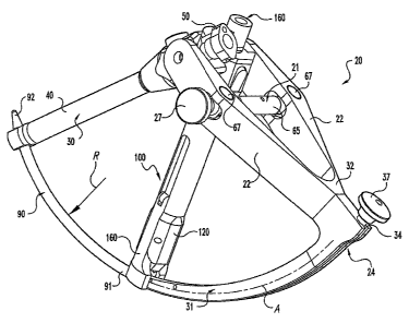
Instruments and methods for insertion of a connecting element for connection
with
anchors engaged to bony parts of the body include installation instrument 20
shown in Fig. 1.
Installation instruinent 20 includes an inserter 24 removably coupled to a
connecting element
90. Installation instrument 20 further includes a first anchor extension 30
and a second
anchor extension 100 mountable to anchors engaged to bony parts of the body.
First anchor
extension 30 is mountable to a first anchor, and second anchor extension 100
is mountable to
a second anchor. Embodiments where instrument 20 includes only a single anchor
and
anchor extension, or three or more anchors and anchor extensions, are also
contemplated.
Inserter 24 is pivotally mounted to anchors extensions 30, 100, and movable
relative thereto
to guide connecting element 90 from a location remote from the anchors to a
location
adjacent the anchors for engagement thereto.
In one embodiment, anchor extension 100 includes first and second members
movable
relative to one another to position the connecting element into a receiver of
the anchor. The
connecting element is moved along an insertion axis A referenced to at least
one of the
CA 02594188 2007-07-03
WO 2006/074191 PCT/US2006/000129
7
anchor extensions, and positioned to a location more proximate to the anchors.
A second
member of anchor extension 100 is mounted to the anchor, and a first member is
movable
relative to the second member and contactable with the connecting element 90
to move it and
the anchor engaged to the second member into a position more proximate one
another. The
anchor extension 100 moves the connecting element transversely to the
insertion axis.
In one form, anchor extension 100 reduces the connecting element into a
passageway of
the anchor, where the connecting element 90 can be secured to the anchor to
stabilize the
spinal column segment to which connecting element 90 is engaged. In still a
further form,
anchor extension 100 is operable to reduce displacement between adjacent
vertebrae, such as
occurs with spondylolisthesis, and then permit engagement of the connecting
element 90 to
anchors engaged to the reduced vertebrae to maintain the vertebrae in a more
aligned
position. Anchor extension 100 provides a further advantage in that reduction
and
stabilization can be completed in a minimally invasive surgical procedure in
which skin and
tissue need not be retracted to expose the misaligned vertebrae.
As discussed further below, inserter 24 is configured to releasably engage
connecting
element 90 and, referenced to anchors in the patient with at least one of the
anchor extensions
30, 100, position connecting element 90 in a position adjacent to and
extending between the
anchors. Anchor extension 100 is configured to contact connecting element 90
and position
connecting element 90 and the anchor to which anchor extension 100 is engaged
in a position
more proximate one another. Anchor extension 30 need not be configured like
anchor
extension 100 in the illustrated embodiment, although it is contemplated that
anchor
extension 30 could be replaced with a second anchor extension 100. It is
further
contemplated that a single anchor extension or three or more anchor extensions
30 and/or 100
could be provided for engagement with a corresponding number of anchors, such
as anchors
80 shown in Figs. 28-31.
As further shown in Fig. 31, anchor 80 can include a screw portion 81 with
bone
engaging threads formed on shank 82 and a head 83 that includes tool opening
84, such as a
hex opening or the like, configured to receive a driving tool. In the
illustrated embodiment,
anchor 80 is a multi-axial screw assembly that has a receiver to receive
connecting element
90 in the form of yoke 88 pivotably coupled to head 83 of screw portion 81.
However, the
use of an anchor 80 that does not include a screw having multi-axial
capabilities is not
CA 02594188 2007-07-03
WO 2006/074191 PCT/US2006/000129
8
precluded. As is known in the art, screw portion 81 is capable of being
pivoted within yoke
88 to assume a plurality of angles relative thereto, and rotated relative to
yoke 88 to engage
bony structure with the threaded shank 82. Further examples of multi-axial
screws are
described in U.S. Patents Nos. 5,797,911 and 5,879,350, each of which is
incorporated herein
by reference.
Other embodiment anchors are also contemplated. Anchor 80 can be in the form
of a
bone screw, bolt, staple, hook, tack, saddle, or interbody device, for
example. Anchor 80 can
be provided with a receiver to receive connecting element 90 and secure it to
the bony
structure.
In the illustrated example, anchor 80 includes a connector in the form of yoke
88
having passageway 95 therethrough for receiving connecting element 90. Head 83
of screw
portion 81 is received within and captured at the bottom of yoke 88. Yoke 88
includes arms
86 extending proximally along and positioned on opposite sides of passageway
95. Arins 86
can have internal threads configured to mate with an externally threaded
distal portion 97 of
set screw 96 (Fig. 36.) Set screw 96 has proximal tool engaging portion 98,
and a shoulder
99 between portions 97, 98 that is carried by one of the members of anchor
extensions 30,
100. Set screw 96 is positioned with shoulder 99 supported by the anchor
extension, and is
released by threading distal portion 97 past the supporting member of the
anchor extension.
Proximal portion 98 can further be configured to break-off from distal portion
97 when a
predetermined threshold torque is applied at proximal tool engaging portion
98, thus allowing
a pre-determined and uniform securing force to be applied to connecting
element 90 with
each of the set screws 96. When employed with anchor extension 30, set screw
96 is released
when proximal portion 98 is severed.
Connecting element 90 includes a length between a connecting end 91 and an
insertion
end 92 sufficient to interconnect at least two anchors 80. Connecting element
90 can be an
elongated rod or shaft curved along its length between ends 91, 92 with a
radius of curvature
R. However, it should be understood that connecting element 90 can include any
configuration known for a rod, implant, or fastener. For example, connecting
element 90 can
be a rigid member, or an elastic or super-elastic member in the form of a
cable, band or
artificial ligament that used in tethering or other surgical procedures.
Connecting element 90
can be percutaneously or non-percutaneously inserted with an installation
instrument 20 into
CA 02594188 2007-07-03
WO 2006/074191 PCT/US2006/000129
9
passageways of anchors engaged to a bony structure in the body of an animal
subject to
stabilize the bony structure.
In the illustrated embodiment, inserter 24 includes a distal arm 31 curved at
a single
radius R along an arc A, and connecting element 90 has an axis co-linear with
arc A.
However, it is contemplated that connecting element 90 can have a curvature
that differs
from arc A, or can have a curvature that varies or is compounded along its
length. The
curvature of connecting element 90 can be defined by any one or any
combination of
mathematical relationships, including, for example, linear, exponential,
logarithmic,
trigonometric, geometric, parabolic, quadratic, cubic, hyperbolic, elliptic,
or parametric
relationships.
Connecting element 90 in Fig. 1 is guided into the body of the patient via
inserter 24.
The installation instrument can employ any type of fixed geometric
relationship to insert
connecting element 90 toward the anchors engaged to the bony structure of the
patient. This
fixed geometric relationship can be governed any one or combination of a
pinned joint, a
cam, a four-bar linkage, or a guide member that provides a path for
translational movement
of connecting element 90, for example. Inserter 24 can be mounted to a single
anchor
extension, or to three or more anchor extensions. Connecting element 90 can
further be
guided and positioned in the patient with free hand techniques, image guidance
techniques, or
with other suitable instruments.
Referring now to Figs. 2-5, further details of one embodiment of anchor
extension 30
are shown. Anchor extension 30 includes an inner sleeve 50 that is received
proximally
within a bore 45 of outer sleeve 40. Inner sleeve 50 defines a bore 51
therethrough that
allows tools to extend to the anchor. Distal end 53 of inner sleeve 50
includes a lip 52
extending radially therearound projecting into inner bore 51. Lip 52 can
support a set screw,
such as set screw 96 discussed above, on lip 52 adjacent distal end 53 of
inner sleeve 50.
Outer sleeve 40 includes an end portion 42 at distal end 41 thereof. As shown
in Fig. 2,
end portion 42 has a U- shaped opening to accommodate insertion of connecting
element 90
therethrougli. A pair of opposing arms 44 of end portion 42 are alignable with
the arms 86 of
yoke 88 to receive arms 86 therein with passageway 95 aligned with the passage
between
arms 44.
CA 02594188 2007-07-03
WO 2006/074191 PCT/US2006/000129
When assembled, a longitudinal axis L1 of outer sleeve 50 is alignable with a
longitudinal axis L3 of inner sleeve 40. An alignment pin 63 of inner sleeve
50 is received in
slot 47 of outer sleeve 40 to ensure and maintain proper alignment of inner
sleeve 50 in outer
sleeve 40. Anchor extension 30 further includes a receptacle 48 extending
laterally
5 therethrough transversely to longitudinal axis D. Receptacle 43 opens
laterally adjacent the
proximal end 43, and receives a pin from inserter 24 to mount inserter 24 to
anchor extension
30. A coupling pin 49 is press fit or otherwise secured in receptacle 48
opposite the laterally
opening receptacle to provide a medially extending pin to facilitate coupling
of anchor
extension 30 with anchor extension 100.
10 Inner sleeve 50 includes lower gripping elements or fingers 54 that include
circular
relief portions 77 therebetween to allow flexing of fingers 54. Shoulder 61
limits the depth of
travel of inner sleeve 50 distally into bore 45 of outer sleeve 40. Inner
sleeve 50 further
includes distal and proximal notches 56a, 56b extending transversely to
longitudinal axis L1,
and spaced proximally of fingers 54 and distally of proximal end 55. Outer
sleeve 40
includes a plunger-type spring biased retainer 57 extending therein adjacent
bore 45 having a
cross bar 58 extending transversely from a plunger 59. Cross bar 58 is
selectively
positionable in a desired one of the notches 56a, 56b to hold inner sleeve 50
in a selected
position relative to outer sleeve 40.
When cross-bar 58 is in the proximal notch 56b, lip 52 of inner sleeve 50
projects into
space between arms 42 of outer sleeve 40. Set screw 96 is supported by lip 52,
and its lower
threaded portion extends between arms 44. If not already secured to set screw
96, yoke 88
can then be at least partially threaded onto set screw 96. Movement of inner
sleeve 50
relative to outer sleeve 40 is facilitated by depressing plunger 59 to lift
cross bar 58 out of
proximal notch 56b. Inner sleeve 50 is moved proximally to position cross bar
58 in the
distal notch 56a, drawing yoke 88 between the arms 44 and against end portion
42 with
passage 70 aligned with the U-shaped opening between the arms 44. When cross
bar 58 is in
distal notch 56a, arins 86 of anchor 80 are drawn proximally between arms 44
of outer sleeve
40. Arms 44 define a passage therebetween adapted to receive arms 86 of yoke
88 in form-
fitting engagement and firinly secure yoke 88 of anchor 80 to anchor extension
30. However,
yoke 88 remains pivotal relative to screw portion 81 to allow anchor extension
30 to be re-
positioned for coupling with anchor extension 100 and inserter 24.
CA 02594188 2007-07-03
WO 2006/074191 PCT/US2006/000129
I1
As shown in further detail in Fig. 6, installation instrument 20 includes an
inserter 24.
Further details regarding inserter 24 and techniques for it are provided in
U.S. Patent No.
6,530,929, which is incorporated herein by reference in its entirety. Inserter
24 includes first
and second support arms 22. Support arms 22 come together and are fixedly
connected at a
proximal end 32 of distal arm 31. Distal arm 31 includes a distal end 33 from
which
connecting element 90 extends. Inserter 24 includes a coupling member 38
adjacent distal
end 33 for securing connecting element 90 thereto. Inserter 24 is pivotable
about a pivot axis
P to define a curvilinear arc or insertion axis A. Distal arm 31 of inserter
24 is preferably
curved to follow axis A and facilitate smootli percutaneous insertion and
withdrawal of distal
arm 31 and the connecting element 90 coupled thereto.
Coupling member 38 is pivotally mounted to distal arm 31, and movable thereto
by
manipulating thumb knob 37. Coupling member 38 is in communication with a
distal
opening 35 in distal end 33 that extends proximally therefrom. Coupling member
38
releasably engages connecting element 90 in distal opening 35.
Distal arin 31 includes a channel 34 extending from distal end 33 therealong
toward
proximal end 32. Channel 34 receives a coupler 36 therein that is secured to
inserter 24 by a
nut 39. For the purposes of clarity, nut 39 and coupler 36 are shown displaced
from channel
34 in Fig. 6 except at distal end 33. Coupler 36 is an elongated flexible
member that extends
with insertion axis A from distal end 33 through nut 39 to a thumb knob set
screw 37 adjacent
proximal end 32. Set screw 37 is threadingly received in a threaded opening
formed in nut
39. Coupler 36 is pivotably coupled to coupling member 38, and is operable
with thumb
knob set screw 37 to move coupling member 38 to engage and release connecting
element 90
to inserter 24. Connecting element 90 is positionable in distal opening 35 so
that connecting
element 90 is relatively fixed with respect to inserter 24 by coupling member
38, maintaining
alignment of connecting element 90 along insertion axis A during insertion of
connecting
element 90. In order to grip and release connecting element 90 in opening 35,
coupling
member 38 is selectively actuated by drawing coupler 36 distally and
proximally via
threading of thumb knob 37 relative to lock nut 39.
Support arms 22 have through-holes 23 for receiving a clamping mechanism 21.
Clamping mechanism 21 draws arms 22 toward one another to pivotably secure
anchor
extensions 30, 100 therebetween. Pivot nuts 67 are positionable in respective
ones of the
CA 02594188 2007-07-03
WO 2006/074191 PCT/US2006/000129
12
holes 23. A clamping bar 65 extends between arms 22, and has threaded bores at
each end
that allow bar 65 to be secured to and clamp arms 22 via threaded fastener 26
and a threaded
end of clamping knob 27. Clamping knob 27 is manipulated by the surgeon to
secure or
release extensions 30, 100 from between arms 22.
In the illustrated embodiment, pins 60 are press fit into respective ones of
the openings
62 of arms 22. Anchor extensions 30, 100 are rotatably mounted on adjacent
ones of the
support arms 22 via the adjacent pin 60 extending into laterally opening
receptacles of the
anchor extensions, such as receptacle 48 discussed above. Each arm 22 can be
provided with
a stop bar 64 extending therefrom towards the opposite support arm 22. Stop
bars 64 limit
rotation of inserter 24 along insertion axis A when a stop bar 64 contacts a
corresponding one
of the extensions 30, 100.
Referring now to Figs. 7-16, further details of anchor extension 100 are
shown. In
Figs. 7-9 anchor extension 100 is shown in an assembled form. Anchor extension
100
includes a first member 120 in the form of an outer sleeve and a second member
160
movably received in first member 120. As further shown in Figs. 10-12, first
member 120
includes an enlarged proximal housing portion 122 and a distal portion 124.
Proximal
housing portion 122 includes a medial receptacle 125 and an opposite lateral
receptacle 132
(Fig. 11.) When assembled with inserter 24 and anchor extension 30, medial
receptacle 125
receives coupling pin 49, and lateral receptacle 132 receives a pin 60 of
inserter 24. Medial
receptacle 125 can include a flared recessed portion extending proximally to
facilitate
placement of pin 60 therein.
In Fig. 10, anchor extension 100 is shown in an exploded view with second
member
160 removed, and in Fig. 11 first member 120 is shown in a perspective view
and in a section
view in Fig. 12. First member 120 further includes a passage 128 extending
between and
opening at the proximal and distal ends thereof sized to receive second member
160 therein.
First member 120 includes a drive member receptacle 126 in proximal housing
portion 122
which opens toward a proximal end thereof, and is in communication with
passage 128. A
drive member 104 is positionable in receptacle 126 and engageable to second
member 160 to
move second member 160 relative to first member 120, as discussed further
below.
Proximal housing portion 122 further includes a lock receptacle 130 in
proximal
housing portion 122 opposite drive member receptacle 126. Lock receptacle 130
includes
CA 02594188 2007-07-03
WO 2006/074191 PCT/US2006/000129
13
holes 133 to receive a lock pin 112 therein. Lock receptacle 130 further
includes a recessed
wall 131 extending therealong to an opening 135. Opening 135 is in
communication with
passage 128. A locking mechanism includes lock button 108 pivotally coupled to
proximal
housing portion 122 in receptacle 130 with lock pin 112. A spring 110 biases
lock member
108 to a locked position, as discussed further below.
A cap 102 is engageable to the proximal end face of first member 120 with
fasteners
106. Cap 102 captures drive member 104 in drive member receptacle 126, while
spring
washer 114 maintains contact between drive member 104 and cap 102 to prevent
drive
member 104 from floating in receptacle 130. Drive member 104 includes a tool
engaging
receptacle at its proximal end, and cap 102 includes a first opening 103 to
provide access to
the tool engaging receptacle. Cap 102 further includes a second opening 105
through which a
proximal end portion of inner sleeve 160 extends.
Distal portion 124 of first member 120 includes a first arm 134 and a second
arm 136
with a slot 138 therebetween. First arm 134 includes a first reducing member
140, and
second arm 136 includes a second reducing member 142. Reducing members 140,
142 are
spaced from one another on opposite sides of slot 138 at the distal ends of
arms 134, 136.
Reducing members are tapered distally and include a wedge-shape and fit
between the distal
ends ofjaws 164, 166 when in a reduction configuration. First and second arms
134, 136
include aligned holes 145, 147 on opposite sides thereof. As discussed further
below, first
arm 134 and second arm 136 are attachable to jaws 164, 166 of inner member 160
with guide
pins 144, 146 positionable through holes 145, 147. As shown in further detail
in Fig. 12, first
member 120 includes passage 128 forming an internal lip 129 about first arm
134 and second
arm 136. The distal end of sleeve 162 of second member 160 contacts lip 129 to
limit
displacement of second member 160 distally relative to first member 160
As shown in Figs. 13-16, second member 160 includes a proximal sleeve portion
162.
First jaw 164 and second jaw 166 are pivotally coupled to first ear 176 and
second ear 178 at
a distal end of proximal sleeve portion 162 with first and second pins 180,
182, respectively.
Proximal sleeve portion 162 includes a passage 168 extending therethrough and
opening at
the proximal and distal ends of sleeve portion 162. Proximal sleeve portion
162 includes an
engagement surface 170 along a portion thereof engageable by drive member 104.
Engagement surface 170 can comprise a series of threads which interdigitate
with threads of
CA 02594188 2007-07-03
WO 2006/074191 PCT/US2006/000129
14
drive member 104 such that as drive member 104 is rotated, first member 120 is
moved
distally or proximally relative to second member 160, depending on the
direction of rotation
of drive member 104. Proximal sleeve portion 162 further includes a proximal
notch 172 and
a distal notch 174 for engagement by lock button 108.
First jaw 164 includes a proximal coupling portion 184 to receive first pin
180 and
pivotally couple first jaw 164 to first ear 176. Similarly, second jaw 166
includes a proximal
coupling portion 192 to receive second pin 182 and pivotally couple second jaw
166 to
second ear 178. First jaw 164 includes a distal anchor coupler 186, and a
protrusion 187
extending medially therefrom. First jaw 164 includes a body 188 extending
proximally from
anchor coupler 186, which includes a guide slot 190 extending therethrough.
Similarly,
second jaw 166 includes a distal anchor coupler 194, and a protrusion (not
shown) extending
therefrom toward protrusion 187. Second jaw 166 includes a body 196 extending
proximally
from anchor coupler 194, which includes a guide slot 198 extending
therethrough. Guide
pins 144, 146 extend through respective ones of the guide slots 190, 198 to
couple jaws 164,
166 to respective ones of the arms 134, 136.
Further details ofjaws 164, 166 are shown in Figs. 15-16 with respect to jaw
164, it
being understood that jaw 166 is an identical mirror image. Slots 190, 198
each include a
proximal cammed portion 191 extending proximally toward one another so that
guide pins
144, 146 force anchor couplers 186, 194 away from one another when second
member 160 is
displaced distally relative to first member 120 with drive member 104, as
shown in Figs. 19
and 21. Slots 190, 198 extend parallel to one another distally of cammed
portion 191, so that
when second member 160 is moved proximally relative to first member 120, guide
pins 144,
146 move into the parallel slot portions and move anchor couplers 186, 194
toward one
another to grip arms 86 of anchor 80 therebetween. In the gripping position,
jaws 164, 166
form a passage therebetween sized to permit placement of connecting element 90
therethrough along insertion axis A.
As shown in further detail in Figs. 17 and 18, lock button 108 includes a body
with a
proximal portion 200 and a distal portion 202. Proximal portion 200 is angled
at angle 212
relative to distal portion 202 to facilitate access to button 108 and provide
a more positive
visual indication of the button positioning relative to housing portion 122.
Lock button 108
includes a receptacle 208 opening along a bottom surface thereof. Lock button
108 includes
CA 02594188 2007-07-03
WO 2006/074191 PCT/US2006/000129
a lock member 206 adjacent proximal portion 200 thereof projecting below the
bottom
surface of lock button 108.
In its assembled orientation, as shown in Fig. 10, lock button 108 is
positioned in
receptacle 130. Receptacle 130 includes recessed wall 131 with lock member
opening 135
5 adjacent a proximal end thereof. Lock member 206 projects through lock
button opening 135
for engagement with second member 160. Spring 110 is received in receptacle
208 and
receptacle 130, and extends between lock button 108 and recessed wall 131 to
bias lock
member 206 through opening 135. Pin 112 is positioned through the eyelet of
spring 110 and
openings 210 through the sidewalls of lock button 108. Pin 112 is secured in
openings 133 of
10 proximal housing portion 122 of first member 120. Lock member 206 of lock
button 108 is
engageable in the notches 172, 174 as second member 160 is moved relative to
first member
120, as discussed further below.
Anchor extensions 30, 100 are engageable to anchors 80. When assembled with
anchor
extension 30, yoke 88 is received within end portion 42 at distal end 41 of
outer sleeve 40,
15 such as shown in Fig. 27. Set screw 96 is captured on the distal end of
inner sleeve 50. End
portion 42 includes an internally shaped wall surface that conforms to and non-
rotatably
receives yoke 88 to rigidly secure yoke 88 thereto when plunger 57 is
positioned in the distal
notch 56a.
Anchor extension 100 is engaged to anchor 80 by positioning clamping jaws 164,
166
in their opened configuration on respective sides of the outer surfaces of
arms 86 of yoke 88,
as shown in Figs. 19 and 21. In this position, second member 160 is displaced
as far as
possible distally relative to first member 120, as shown in Fig. 20. Guide
pins 144 are
received in the proximal cammed portions 191 of slots 190, 198, forcing anchor
couplers 186,
194 away from one another so that arms 86 of yoke 88 can be positioned between
anchor
couplers 186, 194.
As shown in Fig. 20, when jaws 164, 166 are in their open configuration of
Figs. 19
and 21, lock button 108 is rotated clockwise and positioned relative to
proximal housing
portion 122 to indicate that lock member 206 contacts an outer surface of
inner member 160
at a location proximal of proximal notch 172. The proximal end of second
member 160 is
positioned flush with the proximal end surface of cap 102 engaged to first
member 120.
CA 02594188 2007-07-03
WO 2006/074191 PCT/US2006/000129
16
In Figs. 22-23, anchor extension 100 is shown in a mounting configuration for
engagement with an anchor, such as anchor 80. In this configuration first
member 120 is in
an interinediate position relative to second member 160 so that guide pins
144, 146 are
located at the proximal ends of the parallel portions of slots 190, 198. Jaws
164, 166 are
biased toward one another to grip arms 86 of yoke 88 between anchor couplers
186, 194.
However, reducing members 140, 142 are spaced proximally from anchor 80 a
sufficient
distance to permit placement of connecting element 90 through the passage
between jaws
164, 166 at a location along insertion axis A between reducing members 140,
142 and the
proximal end of anchor 80.
In this intermediate position, the proximal end of second member 160 projects
proximally from first member 120. Second member 160 is positioned relative to
first
member 120 so that lock member 206 of lock button 108 is received in proximal
notch 172 of
second member 160. Spring I 10 can bias lock button 108 counter-clockwise so
that lock
member 206 is automatically received in proximal notch 172 when aligned
therewith. In this
intermediate position, proximal portion 200 is flush with proximal housing
portion 122 of
first member 120, as shown in Fig. 22. It is contemplated that an audible
click can be
provided by the contact of lock member 206 with the outer surface of second
member 160,
providing an indication that anchor 80 is secured between anchor couplers 186,
194 ofjaws
164, 166.
In Fig. 24 there is shown anchor extension 100 moving toward a reduced
configuration
in which second member 160 is proximally displaced relative to first member
120 to move
reducing members 140, 142 distally and into contact with the connecting
element. Drive
member 104 can be rotated with a driving tool or the like to facilitate
application of the
necessary force to move first and second members 120, 160 relative to one and
to displace
the bony structure to which anchor extension 100 is engaged. Guide pins 144,
146 move
distally along the parallel portions of guide slots 190, 198. Lock member 206
of lock button
108 is moved along an intermediate notch portion 173 (Figs. 13-14) of second
member 160.
This in turn pushes against the bias of spring 110 and positions proximal
portion 200 of lock
button 108 away from proximal housing portion 122 of first=member 120 such
that it is no
longer flush therewith.
CA 02594188 2007-07-03
WO 2006/074191 PCT/US2006/000129
17
In Figs. 25-26 there is shown anchor extension 100 in a reduced configuration
in which
second member 160 is completely proximally displaced relative to first member
120. In this
position of second member 160, lock member 206 is received in distal notch
174, again
positioning proximal portion 200 of lock button 108 flush with proximal
housing portion 122
of first member 120. In the reduced configuration, reducing members 140, 142
are
positioned in the passageway 95 between arms 86 of yoke 88. Second member 160
projects
proximally further from the proximal end of first member 120 than in either
the open or
mounting configurations discussed above. Lock button 108 locks second member
160 in this
reduced configuration with lock member 206 contacting the proximal end wall of
distal notch
174. The positioning of lock button 108 flush with housing portion 122, and
the audible click
provided when lock member 206 is positioned in distal notch 174, provide an
indication to
the surgeon that complete reduction has been obtained. To release second
member 160, distal
portion 202 of lock button 108 can be pressed against the bias of spring 110
to move lock
member 206 out of engagement with distal notch 174, allowing first member 120
to be
displaced proximally relative to second member 160 until jaws 164, 166 release
anchor 80.
Figs. 27-30 illustrate a surgical technique employing anchor extension 100
with
installation instrument 20. Anchor extension 30 and anchor extension 100 are
engaged with a
corresponding one of the anchors 80 engaged to vertebrae 252, 254 of spinal
column segment
250. Vertebrae 252, 254 include a disc space 256 therebetween. Vertebrae 252,
254 can
comprise a portion of the cervical, thoracic, lumbar and/or sacral regions of
the spine. In the
illustrated embodiment, vertebra 254 is misaligned with vertebra 252,
indicative of a
spondylolisthesis condition. It should be understood, however, that anchor
extension 100 and
installation instrument 20 have application in techniques which do not require
or include
correction of spondylolisthesis.
After engagement of screw portions 81 of anchors 80 to respective ones of the
vertebrae 252, 254, anchor extension 30 is engaged to the anchor 80 engaged to
vertebra 252
with set screw 96 partially threaded into yoke 88. Anchor extension 100 is
manipulated to
open jaws 164, 166 for positioning about arms 86 of yoke 88 of the anchor 80
engaged to
vertebra 254. Anchor extension 100 is then manipulated to move second member
160
relative to first member 120 to the intermediate mounting configuration, where
jaws 164, 166
are clamped along the outer surfaces of arms 86 of yoke 88 as discussed above.
CA 02594188 2007-07-03
WO 2006/074191 PCT/US2006/000129
18
Anchor extensions 30, 100 are then manipulated by pivoting yokes 88 to
position
anchor extensions 30, 100 adjacent one another so that pin 49 is received in
receptacle 125 of
second member 120. Inserter 24 is then secured to anchor extensions 30, 100 by
placing one
of the pins 60 in receptacle 132 of second member 120, and the other of pins
60 in the
receptacle 48 of first anchor extension 30. Pins 60 are rotatably received in
the adjacent ones
of receptacle 48 and receptacle 132, and anchor extensions 30, 100 are secured
to support
arms 22 via clamping mechanism 21. Bores 51 and 168 of inner sleeve 50 and
second
member 160. respectively, remain substantially unobstructed for access to
anchors 80 when
installation instrument 20 is assembled.
to Connecting element 90 is secured to distal arm 31 of inserter 24, and is
advanced from
a location outside the patient percutaneously to a location adjacent to
anchors 80. In the
illustrated embodiment shown in Figs. 28-29, the distal or leading end portion
of connecting
element 90 is initially positioned between arms 86 of the anchor 80 engaged to
anchor
extension 30. The proximal or trailing end portion of connecting element 90 is
positioned in
the passage between jaws 164, 166 of second member 160 of anchor extension
100. Reducer
members 140, 142 are positioned proximally of connecting element 90.
Connecting element 90 is then released from inserter 24. The leading end
portion of
connecting element 90 is secured to anchor 80 with a set screw 96 coupled to
anchor
extension 30. Distal arm 31 can be withdrawn from the patient, and inserter 24
uncoupled
with anchor extensions 30, 100.
In Fig. 30, drive member 104 is then rotated to displace second inember 160
proximally
relative to first member 120, placing reducing members 140, 142 into contact
with
connecting element 90. Second member 160 is displaced relative to first member
120 toward
the reducing configuration of anchor extension 100, displacing connecting
element 90
transversely to its insertion axis and toward a position between arins 86 of
the anchor 80
engaged to vertebra 254. In this reduced position, vertebra 254 is pulled into
alignment with
vertebra 252. A set screw 96 can then be advanced through passage 168 of
second member
160 to secure connecting element 90 in anchor 80 of the reduced vertebra 254
to maintain
vertebrae 252, 254 in their aligned position.
Drive member 104 is then rotated in the opposite direction to displace first
and second
members 120, 160 relative to one another to open jaws 164, 166 and release
anchor 80 from
CA 02594188 2007-07-03
WO 2006/074191 PCT/US2006/000129
19
therebetween. Anchor extensions 30, 100 are then withdrawn from the patient.
Vertebrae
252, 254 can be fused or stabilized with one or more interbody devices in the
disc space
positioned through a second access portal, or through an access portal
provided to
accommodate one or both of the anchor extension 30, 100.
Referring to Fig. 31, there is shown anchor extension 100 with an alternate
forin of
jaws 264, 266 coupled to second member 160. Jaw 264 includes a body 288 with
guide slot
290 extending therealong. An anchor coupler 286 is located at a distal end
ofjaw 264.
Similarly, jaw 266 includes a body 296 with guide slot 298 extending
therealong. An anchor
coupler member 294 is located at a distal end ofjaw 264. Guide slots 290, 298
and anchor
couplers 286, 294 can be configured identically to guide slots 190, 198
discussed above with
respect to jaws 164, 166. Guide slots 290, 298 each include a proximal cammed
portion to
bias jaws 264, 266 away from another to facilitate engagement with anchor 80.
Body 288 includes a recessed portion 289 forined by a concavely curved surface
that
faces a recessed portion 297 formed by a concavely curved surface of body 296.
The
concavely curved surfaces of recessed portions 289, 297 are oriented toward
one another to
form a passage 299 therebetween that is larger than passage 95 formed between
arms 86 of
yoke 88. Passage 299 is also larger than the spacing between coupling members
286, 294
engaged with arms 86 of yoke 88. Passage 299 is structured to accommodate
insertion of a
connecting element with an enlarged portion, as discussed further below.
Although passage
299 is shown with a circular shape, other shapes for passage 299 are also
contemplated.
In Fig. 32 anchors 80 are engaged to pedicles of adjacent vertebrae 252, 254
of spinal
column segment 250. Anchor extension 30 is engaged to anchor 80 engaged to
vertebra 252,
and anchor extension 100 includes j aws 264, 266 coupled to the anchor 80
'engaged to
vertebra 254. Inserter 24 is mounted to anchor extensions 30, 100 with trocar
258 coupled to
distal arm 31. Trocar 258 is inserted through passage 299 between jaws 264,
266 and also
into passage 95 adjacent anchor extension 30. Trocar 258 forms an insertion
path through the
tissue to facilitate passage of a connecting element, such as connecting
element 300 shown in
Fig. 34.
Connecting element 300 includes a first end portion that is a distal leading
end portion
302, a second end portion that is a proximal trailing end portion 304, and an
intermediate
portion 306. Intermediate portion 306 is flexible to allow relative movement
between end
CA 02594188 2007-07-03
WO 2006/074191 PCT/US2006/000129
portions 302, 304 to provide a desired stabilization characteristic.
Connecting element 300 is
inserted with inserter 24 such that first end portion 302 and intermediate
portion 306 pass
through passage 299. First end portion 302 is positioned into passage 95 of
the anchor 80
engaged to anchor extension 30. Second end portion 304 is positioned between
jaws 264,
5 266 adjacent passage 299, and intermediate portion 306 is positioned between
anchor
extensions 30, 100.
First end portion 302 is engaged to the adjacent anchor 80 with set screw 96.
As shown
in Fig. 35, inner member 160 with alternate jaws 264, 266 is then moved
relative to outer
member 120 to reduce second end portion 304 of connecting element 300 into
passageway 95
10 of the anchor 80 engaged to vertebra 254. Connecting element 300 can then
be secured to the
respective anchor 80 with set screw 96, as shown in Fig. 36. Connecting
element 300
maintains a restored disc space height and/or alignment between adjacent
vertebrae. In one
form, connecting element 300 preserves motion between the adjacent vertebrae
252, 254.
Further discussion of connecting element 300 will be made with reference to
Figs. 37-
15 42. In Figs. 37-38, connecting element 300 includes intermediate portion
306 in the form of
a flexible member that provides a shock absorbing effect in transmitting
spinal column loads
between the anchors to which it is engaged. Intermediate portion 306 can also
permit relative
movement between first and second end portions 302, 304 to allow motion of the
spinal
column segment to which connecting element 300 is engaged. In one embodiment,
20 intermediate portion 306 provides connecting element 300 with a variable
stiffness profile
between anchors 80. In still further embodiments, intermediate portion 306 can
be comprised
of a resorbable material so that after a period of time the adjacent anchors
are no longer
linked to one another.
First end portion 302 of connecting element 300 includes a tapered leading end
member
308 to provide a dilation effect and facilitate passage through skin and
tissue in percutaneous
insertion procedures. First end portion 302 may also include other
configurations, including
non-tapered configurations. Second end portion 304 can include an end member
314 with an
indexed configuration 316 in the form of a notch for indexed engagement to
inserter 24 to
ensure that connecting element 300 is coupled in and maintained in the proper
orientation
relative to the inserter before and during percutaneous insertion. First end
portion 302 and
second end portion 304 can be substantially rigid to facilitate percutaneous
insertion of
CA 02594188 2007-07-03
WO 2006/074191 PCT/US2006/000129
21
connecting element 300 with inserter 24 and engagement with anchors 80. For
example, first
end portion 302 can dilate tissue to facilitate passage of intermediate
portion 306
therethrough. Other embodiments contemplate that end member 314 is provided
with other
forms suitable for coupling with an inserter instrument. It is further
contemplated that
connecting element 300 can be inserted manually or with instruments other than
inserter 24.
Connecting element 300 is curved along radius R to facilitate insertion along
an arced
insertion path with inserter 24. Other configurations for connecting element
300 are
contemplated, including configurations discussed above for connecting element
90. As shown
in Fig. 37, one or both of the first and second end portions 302, 304 can
include a number of
pits 310, 312, respectively, to provide increased frictional engagement with
the set screw 96
and anchor 80 to which the end portion 302, 304 is engaged. Smooth surface
profiles for one
or both of end portions 302, 304, such as shown in Fig. 38, are also
contemplated.
Various embodiments of connecting element 300 contemplate various techniques
for
securing first and second portions 302, 304 to intermediate portion 306. In
Figs. 39-42, such
alternate embodiments are described with reference to first end portion 302,
it being
understood the second end portion 304 can be similarly configured for
securement with
intermediate portion 306. In Fig. 39 there is shown first end portion 302 and
intermediate
portion 306 with aligned passages for receiving a coupling member 318
therethrough.
Coupling member 318 can be, for example, a rigid rod or wire secured by
crimping end
portions 302, 304 thereagainst. Additionally or alternatively, a pin 320 can
be provided that
extends transversely through coupling member 318 and into end portions 302,
304. Coupling
member 318 links the distal and proximal portions to one another to maintain
intermediate
portion 306 therebetween. End portions 302, 304 can move relative to one
another in
response to flexing of intermediate portion 306. Coupling member 318 can be
bendable to
facilitate this relative movement.
In Fig. 40 there is shown another embodiment coupling member in the form of a
tether
322 extending through the aligned passages in end portions 302, 304 and
intermediate portion
306. Tether 322 includes a stop member 323, illustrated in the form of a knot
providing an
enlarged end sized to prevent entry into the passage through end portion 302.
Other forms
for enlarged end 323 are also contemplated, including a swage, ball, or other
enlarged device
or form at the ends of the passages to secure first end portion 302 and second
end portion 304
CA 02594188 2007-07-03
WO 2006/074191 PCT/US2006/000129
22
to intermediate portion 306. In a further form, a pin 320 can be provided that
extends
through and intersects tether 322 to secure it to respective ones of the end
portions 302, 304.
In Fig. 41 there is shown another embodiment coupling member designated as 328
which extends through intermediate portion 306 and links end portions 302, 304
thereto. A
stop member 326 is received in an enlarged passage portion 324 to provide an
enlarged end
that secures coupling member 328 to first end portion 302, it being understood
that proximal
portion 304 can be similarly arranged. Stop member 326 can axially float or
move in passage
portion 324 in response to compression loads applied to intermediate portion
306, allowing
end portions 302, 304 to move relative to one another. Enlarged passage
portion 324 further
recesses the stop member 326 so that it does not extend or project outwardly
from first end
portion 302.
In Fig. 42, coupling member 328 is axially secured to end portions 302, 304
with a stop
member 330. Stop member 330 can be in the form of a ball or material fragment
that is
larger than the passage through which coupling member 328 extends. Stop member
330 is
recessed in first end portion 302 so that it does not protrude therefrom.
Another embodiment connecting element 500 is shown in Figs. 43-45. In Fig. 43,
only
a part of a first end portion 502 is shown, and in Fig. 44 there is shown a
part of first end
portion 502 and a second end portion 504 spaced therefrom to accommodate a
flexible
intermediate portion 530 therebetween, as shown in Figs. 46 and 47. A coupling
member 528
extends between and flexibly links first and second end portions 502, 504.
First end portion 502 includes a flange 510 extending thereabout at one end of
a rod-
like body 507 and a tapered end member 503 at the opposite end. End member 502
can
facilitate percutaneous introduction and passage of connecting element 500
through skin and
tissue relative to one or more anchors in a minimally invasive procedure. A
first passage 522
extends axially along at least a portion of the length of first end portion
502. First passage
522 opens centrally at flange 510.
Second end portion 504 includes a flange 506 at one end of a rod-like body
505, and a
tapered end member 508 at the opposite end of body 505. A second passage 518
extends
along at least a portion of the length of second end portion 504, and opens
centrally at flange
506. As discussed further below, intermediate flexible portion 530 can be
positioned
between and engaged to flanges 506, 510. Tapered end member 508 can included a
recess
CA 02594188 2007-07-03
WO 2006/074191 PCT/US2006/000129
23
forming an indexed configuration 512 to facilitate engagement with an
insertion instrument in
a desired orientation relative thereto. Second end portion 504 further
includes exterior
crimping recesses 516 in body 505 along second passage 518 to facilitate
receipt of and
crimping of body 505 by a crimping instrument (not shown.)
The rod-like bodies of the end portions 502, 504 can include a circular cross-
section
transversely to longitudinal axis 501. Intermediate portion 530 can include a
cylindrical body
having a circular cross-section transverse to longitudinal axis 501 that is
enlarged relative to
the cross-sections of end portions 502, 504.
Coupling member 528 extends into first and second passages 522, 518 and can be
engaged to second end portion 504 by crimping the sides of body 505 at
recesses 516. The
crimping force collapses body 505 to grip coupling member 528 in passage 518
extending
through body 505. In one embodiment, coupling member 528 is a metal cable, and
body 505
is collapsed by crimping to frictionally and mechanically engage the cable to
body 505 in
passage 518. Coupling member 528 could also be engaged to first end portion
502 in a
similar manner, or in any other manner discussed herein. Other coupling
members are also
contemplated, including those made from non-metal tethers, solid metal rods,
and material
with super memory properties such as Nitinol and shape memory polymers.
Flanges 506, 510 can be adapted to engage flexible intermediate portion 530
therebetween. In one embodiment, flanges 506, 510 include holes, such as holes
507 shown
with respect to flange 506, to receive attachment means such as fasteners,
sutures, threads,
wires, or other devices to engage intermediate portion 530 to the respective
flange. In
another embodiment, intermediate portion 530 is injection molded between
flanges 506, 510.
The injected material can flow into holes 507 in the flanges in order to form
around coupling
member 528 and at least partially around the flanges to provide engagement
therewith. In
still another embodiment, intermediate portion 530 is molded over flanges 506,
510. In any
embodiment, connecting element 500 can be provided with or without coupling
member 528,
and with or without holes in flanges 506, 510.
For embodiments including coupling member 528, it extends from second portion
504
through intermediate portion 530 and into second passage 522 of first end
portion 502. In the
illustrated embodiment of Fig. 43, a stop member 526 is received in an
enlarged passage
portion 524 of first passage 522 to provide an abutment structure that secures
coupling
CA 02594188 2007-07-03
WO 2006/074191 PCT/US2006/000129
24
member 528 to end portion 502. Stop member 526 can axially float or move in
passage
portion 524 away from interinediate portion 530 in response to compression
loads applied to
connecting element 500. The floating capability of stop member 526 allows end
portions
502, 504 to move toward one another and minimize the potential for buckling of
coupling
member 528 in intermediate member 530 in response to axial compression loads
from the
spinal column. The floating stop member 526 allows reduction of the overall
length of the
connecting element 500 in response to compression of the intermediate portion
while
preventing an assembled connecting element 500 from coming apart in response
to tension or
torsional loading. In one embodiment, stop member 526 is a ferrule that is
crimped or rotary
swaged onto the end of a cable comprising coupling member 528. Other
embodiments
contemplate other coupling arrangements as discussed herein.
In the Fig. 43 embodiment, first end portion 502 includes body 507 extending
along a
longitudinal axis 501. Longitudinal axis 501 and body 507 are curved in the
illustrated
embodiment, and first passage 522 extends linearly along first end portion 502
such that it
diverges from longitudinal axis 501 in the direction away from second end
portion 504 and
opens along a sidewall of body 507. Other embodiments coritemplate other
configurations
for passage 522. For example, Fig. 47 shows passage 522 extending along
longitudinal axis
501 to end member 503. An enlarged passage portion 524 is formed in end member
503 in
communication with passage 522, and receives stop member 526 therein. Stop
member 526
is axially movable in passage portion 524 to facilitate compression of
intermediate portion
530 and movement of end portion 502, 502 relative to one another. Placement of
the opening
of passage 524 at end member 503 cam prevent the anchor to which connecting
element 500
is engaged from interfering with movement of stop member 526.
Connecting element 500 can be configured to extend between adjacent vertebrae
for a
single level stabilization procedure, or a multi-level stabilization procedure
as shown in Fig.
46. In Fig. 46 there is shown connecting element 500 witli first and second
end portions 502,
504 and an intermediate portion 510 between flanges 506, 510. Connecting
element 500
extends along longitudinal axis 501. First end portion 502 includes a length
along
longitudinal axis 501 that is greater than the length of second end portion
504 along
longitudinal axis 501. As shown in Fig. 48, connecting element 500 can extend
between
three anchors engaged to respective ones of three vertebrae for a two level
stabilization
CA 02594188 2007-07-03
WO 2006/074191 PCT/US2006/000129
procedure. For example, intermediate portion 530 is positioned between an
outer anchor 80"
and an intermediate anchor 80', and second end portion 504 is engaged to outer
anchor 80".
First end portion 502 extends between and is engaged to intermediate anchor
80' and an outer
anchor 80.
5 In one procedure, anchor 80 is engageable to a first vertebra, anchor 80' is
engageable
to a second vertebra, and anchor 80" is engageable to a third vertebra. When
so engaged,
intermediate portion 530 allows the vertebrae to which anchors 80', 80" are
engaged to move
or flex relative to one another, but limits extension and flexion motion to
provide a stabilizing
effect. First end portion 502 is engaged to intermediate anchor 80' and also
to first outer
10 anchor 80. When so engaged, the vertebrae to which anchors 80', 80 are
engaged are rigidly
coupled to one another to prevent relative movement therebetween.
Connecting element 500 can be guided into positioin between the anchors using
an
installation instrument as discussed above. The installation instrument may
include extenders
extending from any one, two or three of the anchors. Other techniques
contemplate insertion
15 with an open surgical technique, or guiding of the connecting element
distally along
extenders extending proximally from one or more of the anchors. Connecting
element 500
can be employed in fusion procedures or in procedures employing dynamic
stabilization
without fusion. In fusion procedures, fusion promoting material and/or one or
more fusion
devices, implants, or bone graft are placed in the disc space between adjacent
vertebrae. In
20 such procedures, a single level connecting element may be coupled between
the vertebrae if
dynamic stabilization is desired. If rigid stabilization is desired, a
connecting element with an
elongated end portion can be provided and engaged between the vertebrae to be
fused, and
one or more adjacent vertebral levels can be dynamically stabilized with the
intermediate
portion 530 engaged between these or more other vertebral levels.
25 While in the illustrated embodiments the connecting elements are shown as
being
adapted to extend along one or two vertebral levels, the connecting elements
can also extend
along three or more vertebral levels. For example, one of the end portions
502, 504 can
include a length that extends along multiple vertebral levels to be fused to
provide rigid
stabilization of these levels, while the other of the end portions 502, 504
includes a length
adapted to extend along at least one vertebral level to provide a flexible
intermediate portion
530 between vertebrae for dynamic stabilization.
CA 02594188 2007-07-03
WO 2006/074191 PCT/US2006/000129
26
In a further embodiment shown in Figs. 49 and 50, a connecting element 600 is
provided with a first end portion 602, a second end portion 604, and a linking
portion 606
therebetween. A first flexible intermediate member 630 is provided between
second end
portion 604 and linking portion 606, and a second flexible intermediate member
640 is
s provided betweeri linking portion 606 and first end portion 602. As shown in
Fig. 50, when
engaged to three vertebrae for a two level stabilization procedure, a flexible
intermediate
portion extends between each of the paired anchors 80, 80' and anchors 80',
80" for dynamic
stabilization of each vertebral level.
Linking portion 606 and/or end portions 602, 604 can include flanges at
opposite ends
thereof to which intermediate portions 630, 648 are engaged, and can include
any other type
of connection or coupling arrangement as discussed above with respect to
connecting
elements 300, 500. In a further embodiment of connecting element 600, linking
portion 606
has a length adapted to extend along one or more vertebral levels, and is
engaged to anchors
secured to vertebrae at each of the corresponding vertebral levels. This
embodiment allows
dynamic stabilization of the vertebral levels located both cephaladly and
caudally of the one
or more vertebral levels to be fused and/or rigidly stabilized by linking
portion 606.
The coupling member embodiments discussed herein can be in the form of a rod,
tether,
cable, wire, suture, or other suitable form and can be made from resorbable or
non-resorbable
material, such as polyethylene, stainless steel, and titanium, for example.
Still other
embodiments contemplate one or more intermediate portions mechanically
attached,
chemically or mechanically bonded to the respective end portions and/or
linking portions
without a coupling member extending through the assembly. For example, the
intermediate
portion can be molded, fused, adhered, riveted, other otherwise attached to
respective ones of
the end portions and/or linking portions.
The flexible intermediate portions discussed herein can be made from any
suitable
material allowing at some motion of the vertebral level along which the
intermediate portion
is engaged. For example, the intermediate portions can be made from
elastomers,
polycarbonateurethane, polyetheretherketone, or other polymer material. The
intermediate
portions can be made from resorbable material. In still another form, the
intermediate
portions include springs, which can be made from metal or other suitable
material.
CA 02594188 2007-07-03
WO 2006/074191 PCT/US2006/000129
27
It is further contemplated that the intermediate portions can be provided with
a varying
stiffness profiles to vary the stiffness properties of the connecting element
and control
movenient of the one or more dynamically stabilized vertebral levels. Such
varying stiffness
profiles can be provided across the cross-section of a single flexible
intermediate portion of a
particular connecting element, or provided between different intermediate
portions of a single
multi-level connecting element, or provided between a number of connecting
elements in a
kit where the connecting elements includes one or more intermediate portions
with a stiffness
profile that varies relative to one or more of the intermediate portions of
the other connecting
elements.
In one embodiment, the hardness characteristics of the material comprising the
flexible
intermediate portion is varied. For example, the durometer of an elastomer
material
comprising the one or more flexible intermediate portions may vary to allow
selection and
implantation of a connecting element providing the desired motion
characteristics for the
vertebral level.
In another embodiment, the connecting element is provided with a coupling
member
the couples the first and second end portions to one another through the
flexible intermediate
portion. The diameter of the coupling member can be varied so that the
connecting elements
with flexible intermediate portions extending about a coupling member with a
greater
diameter are stiffer than connecting elements with a flexible intermediate
portion extending
about a coupling member of lesser diameter.
In a further embodiment, the coupling member can be pre-tensioned so that the
end
portions are compressed against the flexible intermediate portion when engaged
thereto. The
amount of pre-tension can range from 0 to the tensile break strength of the
coupling member.
The greater pre-tension loading of the coupling member results in stiffer
flexible intermediate
portion behavior since the preloading compresses the flexible intermediate
portion between
the end portions.
In still a further embodiment, the length of intermediate portion can be
varied. For
example, as shown in Fig. 51, connecting element 700 includes an intermediate
portion 706
having a length L between the respective end portions 702, 704. The length L
can be varied
between intermediate portions of the same or differing connecting elements to
vary stiffness
profiles. The intermediate portion having the greater length L will be less
stiff than
CA 02594188 2007-07-03
WO 2006/074191 PCT/US2006/000129
28
intermediate portions with a smaller length L. In one particular example, the
range of lengths
L can range from 6 millimeters to 15 millimeters or more as measured out-to-
out of the
flanges 708, 710 engaged to the intermediate portion.
In another embodiment connecting element, the flexible intermediate member can
s include a reduced cross-sectional area to vary the stiffness profile. For
example, Figs. 52A-
52B shown a flexible intermediate portion 730 having a central passage 732 for
receiving a
coupling member, although omission of passage 732 is also contemplated. A
number of
bores 734 are provided axially through the body of intermediate portion 730 to
reduce its
cross-sectional area and thus reduce its stiffness. In one embodiment, bores
734 can be
concentrated or provided in greater proportion along one side of intermediate
portion 730 to
provide a varying stiffness profile across the cross-section of intermediate
portion 730. For
example, the concentrated bores can be oriented adjacent the vertebrae in a
posterior
stabilization procedure. Extension motion between the vertebrae would be met
with greater
resistance by the side of intermediate portion 730 with the greater cross-
sectional area being
more resistant to compression loading resulting from the extension motion.
Flexion motion
between the vertebrae would be provided less resistance due to the side of
intermediate
portion 730 having a lesser cross-section area being positioned adjacent the
vertebrae and
being more easily compressed to allow greater flexion motion.
In still another embodiment connecting element, the flexible intermediate
member 740
in Figs. 53A-53B show a flexible intermediate portion 740 having a central
passage 742 for
receiving a coupling member, although omission of passage 742 is also
contemplated. A
number of bores 744 are provided transversely to the longitudinal axis through
the body of
intermediate portion 740 to reduce its cross-sectional area and thus reduce
its stiffness. In
one embodiment, bores 744 can be concentrated along one side of intermediate
portion 740 to
provide a varying stiffness profile across the cross-section of intermediate
portion 740. For
example, the side of intermediate portion 740 with the concentrated or greater
proportion of
bores 744 can be oriented adjacent the vertebrae in a posterior stabilization
procedure,
providing greater resistance to extension motion between the vertebrae than
flexion motion
between the vertebrae.
Referring now to Fig. 54, there is shown three anchor extensions 100, 100',
100
which can be configured substantially identically to one another. Anchor
extensions 100,
CA 02594188 2007-07-03
WO 2006/074191 PCT/US2006/000129
29
100', 100" are removably engageable to respective ones of anchors 80, 80',
80", which are
engageable to respective ones of three vertebrae. The anchor extensions
include jaws 164,
166 movable relative to one another to releasably engage the respective anchor
therebetween.
The anchor extensions are movable relative one another by pivoting the
respective receiver of
the anchor to which the anchor extension is engaged, allowing the positioning
of proximal
housing portions 122, 122', 122" adjacent one another. The respective
receivers of anchor
80, 80', 80" are aligned so that their respective passages are aligned along
an insertion axis
101. Housing portion 122' can be positioned between and coupled to housing
portions 122,
122" to maintain its orientation therebetween. Other embodiments contemplate
that one or
more of the anchor extensions 100 have another form, such as that shown for
anchor
extension 30.
In Fig. 55 an inserter 24' is coupled to anchor extensions 100, 100', 100".
Inserter 24'
can be substantially identical to inserter 24 discussed above except it is
sized to accommodate
at least three anchor extensions 100, 100', 100" therebetween. Inserter 24'
includes an arm
31' movable along insertion axis 101 by pivoting inserter 24, about the
proximal ends of
anchor extensions 100, 100". Any of the multi-level connecting element
embodiments
discussed above can be releasably coupled to inserter 24', and guided from a
location remote
from the anchors 80, 80', 80" to a position where the connecting element
extends between
anchors 80, 80" 80". Any one or all of the anchor extensions 100, 100', 100"
may include
arms configured with a passage to accommodate an enlarged intermediate portion
of the
connecting element, such as shown in Fig. 31. After positioning of the
connecting element
adjacent the receivers of the anchors, any one or combination of anchor
extensions 100, 100',
100" can be manipulated to reduce displacement between the vertebrae and/or to
reduce the
connecting element into position in the respective receivers of the anchors
80, 80', 80".
In one embodiment, insertion axis 101 is a percutaneous path that extends from
a
location at the skin of the patient through the anchors 100, 100' 100". In
another
embodiment, insertion axis 101 extends between anchor extensions 100, 100',
100" from the
anchors to the skin. The connecting element is guided between the anchor
extensions
through an incision at the skin level and along the anchor extensions to the
anchors. Other
embodiments contemplate placement of the connecting element with other
minimally
invasive and open surgical techniques.
CA 02594188 2007-07-03
WO 2006/074191 PCT/US2006/000129
Referring now to Figs. 56-61 there is shown spinal column segment 250 with
first
vertebra 252 and second vertebra 254. Disc space 256 is between vertebra 252,
254. In Fig.
56 spinal column segment 250 is shown with grade 1 spondylolisthesis, where
vertebra 254 is
the L4 vertebra and vertebra 252 is the L5 vertebra. An anchor 80 is secured
to the pedicles
5 of each of the vertebra 252, 254. It is contemplated that anchor extensions,
such as anchor
extensions 30, 100 discussed above, could be attached to respective ones of
the anchors 80
before anchors 80 are inserted and secured to the vertebrae. It is further
contemplated that
anchors 80 can be secured to the adjacent vertebrae, and then anchor
extensions 30, 100
attached to respective ones of the anchors 80. Anchor extension 30 can be
provided in any
10 form suitable to engage anchor 80 secured to vertebra 252 and extend
percutaneously
therefrom to a location outside the patient's body. Also contemplated are
multi-level
stabilization procedures using anchor extensions and instruments such as shown
in Figs. 54-
55.
In Fig. 57 anchor extensions 30, 100 are shown diagrammatically adjacent
15 corresponding ones of the anchors and in exploded view tlierefrom for
clarity. When anchors
80 include pivotal receivers or yokes 88, anchor extensions 30, 100 can be
manipulated
through the skin and tissue to align the passages of yokes 88 to receive
connecting element
400. Connecting element 400 can be configured like any of the connecting
element
embodiments discussed herein, including those for single level and multi-level
stabilization.
20 The connecting element can provide rigid stabilization, flexible
stabilization or combinations
thereof at various vertebral levels.
In one embodiment, connecting element 400 includes a curved body 404 extending
between a leading tapered end 402 and a trailing end 406. Trailing end 406
includes an
indexed recess 408 for coupling with distal arm 31 of inserter 24 as discussed
above. Anchor
25 extensions 30, 100 can be coupled together at their proximal ends and
mounted with an
inserter, such as inserter 24. Inserter 24 guides insertion of connecting
element 400 along a
percutaneous insertion path 414 aligned with the at least the passages of yoke
of the anchor
80 secured to vertebra 252. In a further embodiment, an inserter type
instrument can be
coupled to only of the anchor extensions 30, 100 to percutaneously guide the
connecting
30 element to a location adjacent the anchors.
CA 02594188 2007-07-03
WO 2006/074191 PCT/US2006/000129
31
Alternatively, connecting element 400 can be percutaneoulsy inserted through
an
incision 412 in the skin and tissue 410 between anchor extensions 30, 100.
Connecting
element 400 can be held with forceps or other suitable insertion instrument,
such as described
in U.S. Patent No. 10/202,918 filed July 25, 2002, which is incorporated
herein by reference.
In such a procedure, connecting element 400 could be provided without a
tapered leading end
or indexed trailing end. Furthermore, the inserter is not mounted to one or
both of the anchor
extensions 30, 100 during insertion of the connecting element.
In either procedure, one end of connecting element 400 is positioned in the
passage of
the anchor 80 secured to vertebra 252, i.e. the vertebra that is not
misaligned, as shown in
Fig. 58. The opposite end of connecting element 400 is positioned above the
passage of yoke
88 of the anchor 80 secured to vertebra 254. As shown in Fig. 59, a set screw
96 is delivered
through or along anchor extension 30 and provisionally tightened to secure
connecting
element 400 to the anchor 80 secured to vertebra 252. If necessary, anchor
extension 100 can
be manipulated to contact connecting element 400 and push it toward vertebra
242 change the
angle at which connecting element 400 extends from the anchor 80 secured to
vertebra 252.
Set screw 96 can then be re-tightened to secure connecting element 400 in the
adjusted
position. This adjustment may be desired to reduce the amount of reduction of
vertebra 254
required to position connecting element 400 in the passage of the anchor 80
secured thereto.
Anchor extension 100 is then manipulated as discussed above to draw anchor 80
and
vertebra 254 into alignment with the vertebra 252 and position connecting
element 400 in the
passage of yoke 88 of the anchor 80 secured to vertebra 254, as shown in Fig.
60. A set
screw 96 is then delivered through anchor extension 100 to secure connecting
element 400 to
anchor 80 of vertebra 254 as shown in Fig. 61. The set screw 96 of anchor 80
secured to
vertebra 252 can be further tightened if necessary. The anchor extensions 30,
100 can then be
removed and connecting element 400 maintains vertebrae 252, 254 in align
positioned
relative to one another.
While the invention has been illustrated and described in detail in the
drawings and
foregoing description, the same is to be considered as illustrative and not
restrictive in
character. All changes and modifications that come within the spirit of the
invention are
desired to be protected.