Language selection

Search

Patent 2594206 Summary

Third-party information liability

Some of the information on this Web page has been provided by external sources. The Government of Canada is not responsible for the accuracy, reliability or currency of the information supplied by external sources. Users wishing to rely upon this information should consult directly with the source of the information. Content provided by external sources is not subject to official languages, privacy and accessibility requirements.

Claims and Abstract availability

Any discrepancies in the text and image of the Claims and Abstract are due to differing posting times. Text of the Claims and Abstract are posted:

  • At the time the application is open to public inspection;
  • At the time of issue of the patent (grant).
(12) Patent: (11) CA 2594206
(54) English Title: PROCESS FOR MAKING SWAGED LIGHTING HOLES IN PLANAR AREAS OF PREIMPREGNATED COMPOSITE PARTS
(54) French Title: PROCEDE DE FABRICATION DE TROUS D'ECLAIRAGE EMBOUTIS DANS DES ZONES PLANES DE PIECES COMPOSITES PREIMPREGNEES
Status: Deemed expired
Bibliographic Data
(51) International Patent Classification (IPC):
  • B29C 70/54 (2006.01)
  • B29C 70/34 (2006.01)
(72) Inventors :
  • CANO CEDIEL, DAVID (Spain)
  • MENENDEZ MARTIN, JOSE MANUEL (Spain)
  • PEREZ PASTOR, AUGUSTO (Spain)
  • DURAN QUIROGA, ANTONIO (Spain)
  • NOGUEROLES VINES, PEDRO (Spain)
(73) Owners :
  • AIRBUS OPERATIONS S.L. (Spain)
(71) Applicants :
  • AIRBUS ESPANA, S.L. (Spain)
(74) Agent: BERESKIN & PARR LLP/S.E.N.C.R.L.,S.R.L.
(74) Associate agent:
(45) Issued: 2013-09-17
(86) PCT Filing Date: 2005-12-26
(87) Open to Public Inspection: 2006-07-06
Examination requested: 2010-12-21
Availability of licence: N/A
(25) Language of filing: English

Patent Cooperation Treaty (PCT): Yes
(86) PCT Filing Number: PCT/EP2005/057171
(87) International Publication Number: WO2006/069989
(85) National Entry: 2007-06-27

(30) Application Priority Data:
Application No. Country/Territory Date
P200403146 Spain 2004-12-30

Abstracts

English Abstract


The invention relates to a process for making swaged lighting holes (1) in
planar areas of parts (5) made of preimpregnated composite, by means of which
the part (5) is arranged between a female tooling (11) with the final shape of
the bottom side of the swaged part and a caul plate (19) with the final shape
of the top side of the swaged part, except in an area (3) which must be
swaged, pressure P1 is applied on the caul plate (19) in the area of the part
(5) that must be maintained substantially planar, and pressure P2 is applied
by means of a male tooling (17) on the area (3) of the part (5) which must be
swaged at a forward speed allowing the flow of the resin during the slippage
of the fibers of the material so that it may deform, adapting to the final
shape of the female tooling (11).


French Abstract

La présente invention concerne un procédé de fabrication de trous d~éclairage emboutis (1) dans des zones planes de pièces (5) faites de composite préimprégné, selon lequel la pièce (5) est disposée entre un outil femelle (11) avec la forme finale du coté inférieur de la pièce emboutie et un plateau de compression (19) avec la forme finale du côté supérieur de la pièce emboutie, sauf dans la zone (3) qui doit être emboutie, une pression P1 est appliquée sur le plateau de compression (19) dans la zone de la pièce (5) qui doit être conservée sensiblement plane et une pression P2 est appliquée au moyen d~un outil mâle (17) sur la zone (3) de la pièce (5) qui doit être emboutie à une vitesse d~avancement permettant l~écoulement de résine pendant le glissement des fibres du matériau afin qu~elle puisse se déformer, s~adaptant à la forme finale de l~outil femelle (11).

Claims

Note: Claims are shown in the official language in which they were submitted.

5

The invention claimed is:
1. A process for forming a swaged lighting hole in a planar or quasi-
planar
area of a part made of a laminate of preimpregnated composite tape containing
stiff
continuous fibers, said laminate having been produced by means of a tape
laying
machine, which comprises the following steps:
a) Arranging the part containing said lighting hole between a female
tooling with the final shape of the bottom side of the swaged part and a caul
plate with the final shape of the top side of the swaged part, except in the
area
that must be swaged, which is not covered by the caul plate, and applying
pressure on the caul plate throughout the process to prevent the formation of
wrinkles on the area of the part that must be maintained substantially planar;
b) Locating a spring within the lighting hole oriented to oppose
pressure applied in a direction perpendicular to the female tooling;
c) Applying a male tooling against the resistance of said spring on the
area of the part which must be swaged such that the forward speed of said
male tooling results in flow of the resin and slippage of the fibers of the
laminate, such that said part can be deformed, adapting to the shape of the
female tooling.
2. A process according to claim 1, wherein the part of the male tooling in
contact with the part is configured with the final shape of the swaged
lighting hole
and does not deform during the process.
3. A process according to claim 1, wherein the part of the male tooling in
contact with the part is deformable, such that it can exert pressure uniformly
on the
area of the part which must be swaged to adapt to the shape of the female
tooling.
4. A process according to claim 1, wherein it also comprises the
application to heat to the part to achieve a temperature in the resin
facilitating the
slippage of the fibers of the laminate.
5. A process according to claim 4, wherein it also comprises a final
cooling step of the part.

Description

Note: Descriptions are shown in the official language in which they were submitted.


CA 02594206 2007-06-27
WO 2006/069989 PCT/EP2005/057171
1
PROCESS FOR MAKING SWAGED LIGHTING HOLES IN PLANAR AREAS
OF PREIMPREGNATED COMPOSITE PARTS
FIELD OF THE INVENTION

This invention relates to a process for making swaged lighting holes in
planar areas of preimpregnated composite parts, and particularly in parts made
by means of automatic laying machines.

BACKGROUND OF THE INVENTION

The use of swaged lighting holes in structural parts is common in order to
achieve an increase of stiffness without increasing the weight and with a
minimum cost.
The processes for making swaged lighting holes on sheet metal are
common in industry and achieve the desired deformation of the sheet by means
of its plastic deformation.
In the case of composite parts formed with stiff continuous fibers,
however the mechanism allowing the adaptation to the desired shape of the
swaged lighting hole is based on the relative slippage of fibers.
In parts made with composites, the traditional process for making
swaged lighting holes consists of manually laminating each layer, adapting it
to
the geometry of the swaged lighting hole. This process is expensive, since it
is
completely manual and requires the use of materials that can adapt to the
complex geometry of the swaged lighting hole without forming wrinkles. The
most adaptable type of material is fabric, which, compared with the tape, is
more expensive and has worse structural properties.

SUMMARY OF THE INVENTION
This invention proposes a new process for achieving swaged lighting
holes in planar or quasi-planar areas of laminated parts of preimpregnated
composite that is particularly applicable to parts made using preimpregnated


CA 02594206 2007-06-27
WO 2006/069989 PCT/EP2005/057171
2
tape the laminate of which is carried out with an automatic laying machine.
Parts of this type are used quite particularly in the aeronautical industry.
The process comprises the following steps:
- Arranging the part between a female tooling with the final shape of the
bottom side of the swaged part and a caul plate with the final shape of the
top
side of the swaged part and applying pressure on the caul plate throughout the
process to prevent forming wrinkles on the area of the part that must be
maintained sufficiently planar. The caul plate will not act on the area of the
part
with the swaged lighting hole.
- Applying a male tooling on the area of the part that must be swaged at
a forward speed allowing flow of the resin during the slippage of the fibers
of the
composite such that said area can be deformed, adapting to the shape of the
female tooling.
The process may additionally include the application of heat to the part
while carrying out the process to achieve a temperature in the resin
facilitating
the slippage of the fibers of the material and a final cooling step if its
handling is
required immediately after making the swaged lighting hole.
Other features and advantages of this invention will be understood from
the following detailed description of an illustrative embodiment of its object
in
relation to the attached drawings.

BRIEF DESCRIPTION OF THE DRAWINGS

Figure 1 shows the starting part in the process according to this
invention.
Figure 2 shows the part of Figure 1 after making two swaged lighting
holes following the process object of this invention.
Figure 3 shows a part in which the flanges are formed first and after that
the swaged lighting holes are made following the process object of this
invention.
Figure 4 shows a schematic view of the part and of devices used to carry
out the swaged lighting hole process according to this invention upon
beginning


CA 02594206 2007-06-27
WO 2006/069989 PCT/EP2005/057171
3
the process.
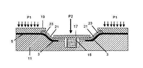
Figure 5 shows a schematic view of the part and of said devices upon
concluding the process.

DETAILED DESCRIPTION OF THE INVENTION

An embodiment of the process according to the invention for carrying out
the swaged lighting hole 1 consisting, as is shown in the cases represented in
Figures 2 and 3, of a recess of an area 3 of the part 5 surrounding the
opening
7, with an S-shaped contour, is described below. As the person skilled in the
art
will understand, the swaged lighting hole may have another shape.
The swaged lighting holes 3 are made in a planar or quasi-planar area of
the part 5, but the latter may have a non-planar shape like the part 5 shown
in
Figure 3, which corresponds to a rib with a C-shaped section, in which the
flanges 6 have been formed prior to making the swaging according to this
invention.
The part 5 is covered with a thin plastic film (not represented) to prevent
it from adhering to the tooling of the swaged lighting hole process and is
placed, suitably centering it, on a female tooling 11 the top side of which
reproduces the shape that the part must be given during the swaging process,
particularly including the cavity 13 with the desired shape for the swaged
lighting hole 1.
A male tooling 17 and a caul plate 19 are arranged on the part 5. This
caul plate 19 must cover the entire area affected by the movement that the
swaging process will cause on the fibers of the composite, except in the very
swaged lighting hole areas. The part 5 is therefore enclosed between the
female tooling 11 and the caul plate 19, except on area 3.
The male tooling 17 is responsible for forming the part 5 with the shape
of the female tooling 11, and particularly forming its area 3 with the shape
of the
cavity 13. The male tooling 17 must initially be lifted above the part 5,
which is
achieved by supporting it on the female tooling 11 by means of springs 15.
The male tooling 17 may have the final shape of the swaged lighting hole


CA 02594206 2007-06-27
WO 2006/069989 PCT/EP2005/057171
4
1 on its side that is applied on the part 5 or, as is shown in Figures 4 and
5, with
the part 21 coming into contact with the part 5 made of a deformable material
such that it may begin contact with the part in the area 23 where the swaged
lighting hole begins and progressively become deformed until exerting pressure
uniformly on the area 3 of the part 5 against the cavity 13 of the female
tooling
11.
After the foregoing, the swaged lighting hole process is carried out in the
following steps:
- Applying pressure P1 on the caul plate 19 such that the part 5 is
enclosed and compressed between the caul plate 19 and the female tooling 11,
preventing the formation of wrinkles.
- In the case of using a material preimpregnated with a high viscosity
resin, applying heat until achieving the suitable temperature to reduce the
resin
viscosity, facilitating the slippage of the fibers among one another.
- Applying pressure P2 on the male tooling 17 so that it moves on the
part 5 at a rate such that it allows the slippage of the fibers inside the
part as the
geometry of its area 3 evolves until achieving complete adaptation on the
female tooling forming the swaged lighting hole 1.
- In the case of having heated the part 5 and a subsequent handling
being necessary, cooling it to room temperature to return it to its initial
consistency.
Any modifications comprised within the scope defined by the following
claims can be introduced in the preferred embodiment described above.

Representative Drawing
A single figure which represents the drawing illustrating the invention.
Administrative Status

For a clearer understanding of the status of the application/patent presented on this page, the site Disclaimer , as well as the definitions for Patent , Administrative Status , Maintenance Fee  and Payment History  should be consulted.

Administrative Status

Title Date
Forecasted Issue Date 2013-09-17
(86) PCT Filing Date 2005-12-26
(87) PCT Publication Date 2006-07-06
(85) National Entry 2007-06-27
Examination Requested 2010-12-21
(45) Issued 2013-09-17
Deemed Expired 2020-12-29

Abandonment History

There is no abandonment history.

Payment History

Fee Type Anniversary Year Due Date Amount Paid Paid Date
Application Fee $400.00 2007-06-27
Maintenance Fee - Application - New Act 2 2007-12-27 $100.00 2007-06-27
Registration of a document - section 124 $100.00 2007-11-19
Maintenance Fee - Application - New Act 3 2008-12-29 $100.00 2008-12-08
Maintenance Fee - Application - New Act 4 2009-12-29 $100.00 2009-12-08
Maintenance Fee - Application - New Act 5 2010-12-29 $200.00 2010-12-09
Request for Examination $800.00 2010-12-21
Registration of a document - section 124 $100.00 2011-04-11
Maintenance Fee - Application - New Act 6 2011-12-26 $200.00 2011-12-22
Maintenance Fee - Application - New Act 7 2012-12-27 $200.00 2012-11-20
Final Fee $300.00 2013-07-02
Maintenance Fee - Patent - New Act 8 2013-12-27 $200.00 2013-12-16
Maintenance Fee - Patent - New Act 9 2014-12-29 $200.00 2014-12-15
Maintenance Fee - Patent - New Act 10 2015-12-29 $250.00 2015-12-14
Maintenance Fee - Patent - New Act 11 2016-12-28 $250.00 2016-12-13
Maintenance Fee - Patent - New Act 12 2017-12-27 $250.00 2017-12-18
Maintenance Fee - Patent - New Act 13 2018-12-27 $250.00 2018-12-18
Maintenance Fee - Patent - New Act 14 2019-12-27 $250.00 2019-12-16
Owners on Record

Note: Records showing the ownership history in alphabetical order.

Current Owners on Record
AIRBUS OPERATIONS S.L.
Past Owners on Record
AIRBUS ESPANA, S.L.
CANO CEDIEL, DAVID
DURAN QUIROGA, ANTONIO
MENENDEZ MARTIN, JOSE MANUEL
NOGUEROLES VINES, PEDRO
PEREZ PASTOR, AUGUSTO
Past Owners that do not appear in the "Owners on Record" listing will appear in other documentation within the application.
Documents

To view selected files, please enter reCAPTCHA code :


To view images, click a link in the Document Description column. To download the documents, select one or more checkboxes in the first column and then click the "Download Selected in PDF format (Zip Archive)" or the "Download Selected as Single PDF" button.

List of published and non-published patent-specific documents on the CPD .

If you have any difficulty accessing content, you can call the Client Service Centre at 1-866-997-1936 or send them an e-mail at CIPO Client Service Centre.


Document
Description 
Date
(yyyy-mm-dd) 
Number of pages   Size of Image (KB) 
Abstract 2007-06-27 1 76
Claims 2007-06-27 1 39
Drawings 2007-06-27 2 74
Description 2007-06-27 4 161
Representative Drawing 2007-06-27 1 12
Cover Page 2007-09-20 1 51
Claims 2012-04-25 1 45
Claims 2012-12-05 1 43
Drawings 2012-12-05 2 77
Representative Drawing 2013-08-21 1 15
Cover Page 2013-08-21 1 57
Prosecution-Amendment 2010-12-21 1 49
PCT 2007-06-27 2 61
Assignment 2007-06-27 4 113
Correspondence 2007-09-15 1 26
Assignment 2007-11-19 3 112
Assignment 2011-04-11 17 608
Prosecution-Amendment 2012-04-25 7 277
Prosecution-Amendment 2012-06-28 2 66
Prosecution-Amendment 2012-12-05 4 141
Correspondence 2013-07-02 1 47