Note: Descriptions are shown in the official language in which they were submitted.
CA 02594271 2007-06-22
WO 2006/071758 PCT/US2005/046727
HYDRATING ANHYDROUS GRAFT MATERIALS
TECHNICAL FIELD
[01] This invention relates to the hydration of anhydrous materials.
The invention finds particular utility in the hydration of synthetic or
cadaver
bone graft materials with a mixture of cell concentrates and thrombin.
BACKGROUND
[02] Surgical procedures and therapies often include the addition of a
matrix to facilitate healing. This may be a skin graft or a bone graft. A
typical
treatment of a bone defect would include debridement, mechanical
stabilization, graft application, then closing and caring. There are many
sources for graft materials, including cadavers and synthetic materials. It is
convenient to manufacture, ship, and store these materials in the anhydrous
state. They can be hydrated at the point of care with sterile water, 0.9%
NaCI,
or biological fluids. Many anhydrous bone graft materials are available both
as a contiguous component and granular in structure. A useful hydration
method involves hydration with a mixture of platelets, fibrinogen, and
thrombin. Using biological fluids, a granular graft material can be hydrated
with a clotting fluid, formed into a desired shape, and allowed to clot to
improve the handling characteristics in the surgical field.
SUMMARY OF THE INVENTION
[03] In accordance with the invention, a container is provided to
receive and contain anhydrous graft material during hydration with a selected
hydrating fluid. The container is preferably tubular and provides an opening
at
one end for placing the anhydrous graft material in the container. The
container may take any of various forms, however, and may be made of rigid,
semi-rigid or flexible materials. A handle is optionally available for
insertion
into the container and tamping the graft material against a wall or other
surface of the container to insure that the finished graft is free of voids
and
gaps.
[04] The hydrating fluid is then introduced into the container having
the anhydrous material therein by a means for supplying. The fluid may be
introduced into the container in any of several ways. For example, the
hydrating fluid may be introduced through the opening through which the graft
1
CA 02594271 2007-06-22
WO 2006/071758 PCT/US2005/046727
material was inserted. Preferably, the container is provided near the position
of the graft material with means for connecting to a source of hydrating
fluid.
The means for connecting is preferably a fluid port configured to attach
easily
to containers having the hydrating fluid for transferring the hydrating fluid
to
the container. Preferably, the fluid port is in the form of a Luer lock for
allowing the container to be connected to a variety of known medical
products, including syringes and flexible tubes.
[05] The means for supplying, which may be a single source or may
be a plurality of sources. If the hydrating fluid is to be obtained from a
single
source, it can be supplied to the container through the open end through
which the graft material was inserted or it may be supplied through the fluid
port. In a preferred embodiment, the fluid is supplied through the fluid port
by
connecting a syringe containing the fluid to the fluid port and injecting the
hydrating fluid.
[06] If the hydrating fluid is a mixture of fluids, such as a cell
concentrate and thrombin, the means for supplying may comprise two
syringes, with each having one of the fluids to be mixed. The two syringes
are preferably connected together with a Y-set that combines the fluids into a
single stream for introduction to the container. A known such arrangement
includes a clip that is attached to the fluid syringe handles whereby the
syringes inject the two fluids into the container having the graft to be
hydrated
at a fixed ratio.
[07] In the preferred embodiment, the container is tubular with one
end open and the other end tapering to the fluid port. Means for supporting
the material is placed at the end nearest the fluid port for use in ejecting
the
hydrated graft material. The means for supporting provides support for the
material to be hydrated to prevent the break-up of clots during ejection of
the
material. In this embodiment, hydrating fluid is introduced to the container
and injected into the graft material through thru the fluid port. In the
preferred
embodiment, the means for supporting comprises a piston having channels
for passing the hydrating fluid. Alternatively, the means for supporting may
be
a porous matrix capable of supporting the material, a screen, or the like.
Fluid
flows evenly about the piston through the channels designed to allow the
2
CA 02594271 2007-06-22
WO 2006/071758 PCT/US2005/046727
passage of fluids. If the hydrating fluid includes biologic materials that
will
form a clot, the tube is allowed to stand until the fluids have clotted the
graft.
[08] The hydrated graft is then ejected through the large end of the
tube by a means for ejecting. For example, the means for ejecting may
comprise a rod, and the material is ejected by pushing the piston with the rod
inserted through the other end of the tube, e.g., the fluid port. The means
for
ejecting may also include structure, such as a sling, that allows the material
to
be lifted from the container. For example, the material may be ejected by
providing an element accessible from the first end of the container to lift
the
means for supporting and the graft material out of the container. By way of
example, a flexible string or cord could be attached to the means for
supporting.
[09] The large first end of the tube preferably has an annular ring that
forms a stop to retain the means for supporting in the tube. For example, the
shape of the piston allows the graft-contacting surface of the piston to
extend
beyond the end of the container to ensure ejection of the hydrated graft.
[10] When the hydrating fluids are to be a mixture, different fluid
syringe diameters of the means for supplying can be used to obtain the
desired ratio of fluids delivered to the graft. In the preferred embodiment
the
clip that attaches to the fluid syringe handles is designed so the syringes
will
be fully evacuated simultaneously. The volume of a cylinder is the product of
pi, the square of the radius, and the length (i.e., -rrr2=C). In the preferred
embodiment, this system uses a clip on the syringe handles whereby the
length is equal for both syringes even when different total volumes are used,
which means that one must consider the ratio of the cross sectional areas of
the interiors of syringes. So, the hydration fluid delivery ratio is simply
the
ratio of the syringes' cross-sectional areas (Tr-r).
[11] Appropriate combinations for standard syringes are:
[12] 5:1 for a 20m1 and 3mi syringe;
[13] 3:1 for a 10mI and 3mi syringe; and
[14] 10:1 for a 10mI and 1 mI syringe.
[15] Custom syringes with other diameters can be designed to give
other ratios.
3
CA 02594271 2009-01-30
[16] For two syringes, the hydrating fluid would be whole blood,
plasma, platelet rich plasma, platelet poor plasma, platelet concentrate, bone
marrow concentrate, or bone marrow aspirate. The second fluid would be
bovine or autologous thrombin.
[17] One syringe of fluid can be attached to the tube with a fitting.
[18] Multiple syringes can be attached with a manifold.
[19] The tube may be shapes other than round and may have
various diameters. The tube may be of almost any shape, such as a box with
a lid.
[20] Graft material can be any anhydrous material, skin, bone,
synthetic or cadaver, etc.
[21] A stand (not shown) may also be provided to hold the container
upright while clotting.
[22] The invention provides several unique features. For example
the invention provides mixing of the thrombin with other fluids as they enter
the tube and before distribution to the graft. Different ratios can be
obtained
by using different diameter syringes for the cell concentrate and the
thrombin.
The piston is provided with channels adjacent the inside of the tube to
distribute the fluid evenly before the fluid is introduced to the graft
material.
The piston fits the shapes of the tube closely to reduce fluid hold-up volume.
The large open end of the tube has a section that is of reduced diameter
intended to retain the piston inside the tube. The piston is shaped such that
a
portion of the graft end of the piston can fit past the reduced diameter of
the
large open end of the tube. This allows ejection of the graft past the walls
of
the tube while still retaining the piston in the tube. The length of the rod
is
such that the handle of the rod becomes incident to the small end of the tube
and does not allow the ejection piston to be pushed out of the large end of
the
tube. The amount of graft material can be varied. The graft material can be
tamped inside the tube to reduce voids and gaps in the material. The amount
of fluid and the ratio of two or more fluids can be varied.
[22A] According to an embodiment of the present invention there is
provided an apparatus for treating a first material with a second material
comprising a container having a first opening and a second opening and
configured to receive the first and second materials. The first opening is
4
CA 02594271 2009-01-30
configured to admit the first material to the container and the second opening
is configured to admit the second material to the container. The apparatus
includes means for ejecting the first material from the container through the
first opening. The apparatus further comprises means for supporting the first
material in the container, the means for supporting are porous to the second
material.
[22B] According to another embodiment of the present invention there
is provided an apparatus for treating a biologic material with a biologic
liquid
comprising an elongate container having a first opening at one end configured
to receive the biologic material and a second opening at a second end
configured to receive the biologic liquid. The apparatus includes supporting
means for supporting the material in the elongate container, and means for
ejecting the biologic material from the container through the first opening by
engaging the supporting means.
BRIEF DESCRIPTION OF THE DRAWINGS
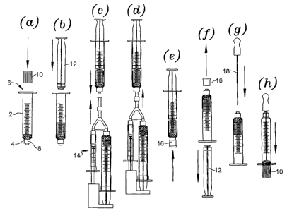
[23] Figures 1(a) through 1(h) show apparatus in accordance with
the invention and a process for its use.
[24] Figure 2 shows the end portion of a preferred container.
4a
CA 02594271 2009-01-30
[25] Figure 3 is a side view of a preferred supporting element used
with the container of figure 2.
DETAILED DESCRIPTION OF THE PREFERRED EMBODIMENT
[26] With reference to figure 1, a preferred embodiment of the
invention is illustrated. In figure 1a, a container 2 in the form of a
cylindrical
tube similar to a known syringe is provided. The syringe includes an ejection
plug 4, which will be described in detail below. The container has an open
upper end 6 and a fluid port 8 at the opposed end. In the step illustrated in
figure 1a, the graft material 10 is placed in the container.
[27] In the step illustrated in figure 1 b, a plunger 12 is inserted
through the open end and used to tamp the graft material. The plunger does
not seal the cylinder whereby air displaced from the material can escape.
[28] Figure 1 c illustrates the connection of a known means for
supplying in the form of a dual syringe system 14 that has been supplied with
the desired hydration fluid. The system includes two syringes of different
volumes and a connector "Y" whereby one syringe, for example, may be
supplied with a cellular material and the other with thrombin. The "Y"
connector is attached to the fluid port 8, and the plunger of the system 14
advanced to inject fluids into the container 2 as illustrated in figure 1d.
[29] In figure le, a protective cap 16 is applied to the fluid port after
removal of the system 14, and the container is allowed to stand until the
fluids
clot.
[30] Figure 1f illustrates the first step for ejecting the hydrated graft.
In this process, the cap 16 and plunger 12 are removed. An ejection rod 18 is
then inserted through the fluid port or other aperture and engaged with the
ejection plug 4. Downward pressure forces the plug and graft material
downward until the graft is ejected from the container through the end 6 as
shown in figure 1 h.
[31] Figures 2 and 3 illustrate preferred structures for allowing the
plug 4 to extend beyond the end of the container during ejection of the graft.
The plug 4 includes a reduced diameter portion forming a shoulder 20. The
container, in turn includes a stop 22 formed on the interior surface. The plug
may be pushed downward until the stop 22 engages the shoulder 20. At that
point, the portion 24 of the plug may be flush with the end of the tube 2, but
CA 02594271 2007-06-22
WO 2006/071758 PCT/US2005/046727
preferably it is designed such that portion 24 protrudes from the end of the
tube to ensure ejection of the graft material.
[32] The plug is further provided with channels 24 to allow free
passage of the hydrating fluids during the injection step shown in figure 1d.
[33] The top of the plug may be configured to mate with the tip of the
plunger to allow the plug to be rotated or pushed and pulled during ejection
of
the plug.
[34] Modifications will be apparent to those of skill in the art.
6