Language selection

Search

Patent 2594303 Summary

Third-party information liability

Some of the information on this Web page has been provided by external sources. The Government of Canada is not responsible for the accuracy, reliability or currency of the information supplied by external sources. Users wishing to rely upon this information should consult directly with the source of the information. Content provided by external sources is not subject to official languages, privacy and accessibility requirements.

Claims and Abstract availability

Any discrepancies in the text and image of the Claims and Abstract are due to differing posting times. Text of the Claims and Abstract are posted:

  • At the time the application is open to public inspection;
  • At the time of issue of the patent (grant).
(12) Patent Application: (11) CA 2594303
(54) English Title: JOINT PROTECTOR, BLANK FOR A JOINT PROTECTOR AND METHOD FOR MANUFACTURING A JOINT PROTECTOR
(54) French Title: COUVRE-JOINT, EBAUCHE DE COUVRE-JOINT, ET PROCEDE DE FABRICATION D'UN COUVRE-JOINT
Status: Dead
Bibliographic Data
(51) International Patent Classification (IPC):
  • A61F 13/06 (2006.01)
  • A61F 13/10 (2006.01)
(72) Inventors :
  • MAGNUSSON, STEFAN (Sweden)
(73) Owners :
  • OTTO BOCK SCANDINAVIA AB (Sweden)
(71) Applicants :
  • OTTO BOCK SCANDINAVIA AB (Sweden)
(74) Agent: FETHERSTONHAUGH & CO.
(74) Associate agent:
(45) Issued:
(86) PCT Filing Date: 2005-12-30
(87) Open to Public Inspection: 2006-07-13
Availability of licence: N/A
(25) Language of filing: English

Patent Cooperation Treaty (PCT): Yes
(86) PCT Filing Number: PCT/SE2005/002065
(87) International Publication Number: WO2006/073353
(85) National Entry: 2007-07-03

(30) Application Priority Data:
Application No. Country/Territory Date
0500033-6 Sweden 2005-01-07

Abstracts

English Abstract


A joint protector (1) of a sheet-shaped flexible material, including an
essentially tubular body, which is provided with a curved configuration for
adaptation to a joint, and which is sewn together with at least one seam (3) ,
between a first edge of a first material portion (4) and a second edge of a
second material portion (5) , is distinguished in that the seam (3) between
said edges extends along a curve, which defines a recessed area of material
(A) of the first material portion (4) at an essentially central portion of the
first edge, and which defines an enlarged area of material (a) of the second
material portion (5) at an essentially central portion of the second edge,
that the first material portion (4) is provided with a contracting action to
the recessed area of material (A) through the seam (3) for achieving a curved
configuration of the tubular body. The invention also concerns a blank and a
method.


French Abstract

L'invention porte sur un couvre-joint, fait d'un matériau souple en feuille comportant un corps sensiblement tubulaire incurvé pour d'adapter à un joint, et qui est cousu au moyen d'au moins une couture (3) entre un premier bord d'une première portion (4) dudit matériau et un deuxième bord d'une deuxième portion (5) dudit matériau. La couture (3) s'étend le long d'une courbe qui délimite une zone en retrait du matériau (A) de la première portion (4) de matériau en un point sensiblement central du premier bord, et qui délimite une zone élargie du matériau (a) de la deuxième portion (5) de matériau en un point sensiblement central du deuxième bord. La première portion (4) de matériau exerce sur la portion en retrait du matériau (A) par l'intermédiaire de la couture (3) une action contractrice qui confère sa courbure au corps tubulaire. L'invention porte également sur une ébauche et un procédé.

Claims

Note: Claims are shown in the official language in which they were submitted.


12

CLAIMS

1. Joint protector (1) of a sheet-shaped flexible
material, including an essentially tubular body, which is
provided with a curved configuration for adaptation to a
joint, so that the joint protector defines a convex area (2)
for adaptation to an extreme portion of the joint, and which
is sewn together with at least one seam (3), between a first
edge of a first material portion (4) and a second edge of a
second material portion (5), characterized in

- that the seam (3) between said edges extends along a curve,
which defines a recessed area of material (A) of the first
material portion (4) at an essentially central portion of the
first edge, and which defines an enlarged area of material (a)
of the second material portion (5) at an essentially central
portion of the second edge,
- that the first material portion (4) is provided with a
contracting action to the recessed area of material (A)
through the seam (3) for achieving a curved configuration of
the tubular body.

2. Joint protector according to claim 1, characterized
in that the second material portion (5) is provided with a
stretching effect to the enlarged area of material (a).


3. Joint protector according to claim 1 or 2,
characterized in that the extension of the recessed area of
material (A) exceeds the extension of the enlarged area of
material (a) in unloaded state.

4. Joint protector according to claim 1, 2 or 3,
characterized in that the axial height (H) of the first
material portion exceeds the axial height (h) of the second
material portion in unloaded condition as seen in the axial
direction of the joint protector.

5. Joint protector according to any of the previous
claims, characterized in that the length of the first edge


13

(10) exceeds the length of the second edge (11) in unloaded
condition.

6. Joint protector according to any of the previous
claims, characterized in that it has two seams (3, 6) at
essentially opposite sides in order to achieve the curved
configuration of the tubular body.

7. Joint protector according to any of the previous
claims, characterized in that the first material portion (4)
belongs to a first piece of material and that the second
material portion (5) belongs to a second piece of material.

8. Joint protector according to any of the claims 1-6,
characterized in that the first material portion (4) belongs
to at least two first pieces of material.

9. Joint protector according to any of the previous
claims, characterized in that in unloaded state the surface
extension of the enlarged area of material is between about
40% and 80% of the surface extension of the recessed area of
material.

10. Joint protector according to any of the previous
claims, characterized in that in unloaded state, the enlarged
area of material has a general tapering angle, which is about
10°-45° smaller than a general tapering angle of the recessed
area of material.

11. Joint protector according to any of the previous
claims in dependence of claim 6, characterized in that the
shortest distance between the bottoms of two recessed areas of

material of the respective seam is between about 10% and 40%
of the length of the circumference of the joint protector.

12. Joint protector according to any of the previous
claims, characterized in that the sheet-shaped flexible
material is comprised of a laminate of a layer of stretch
material such as knitted textile material on each side of a
porous layer of rubber or rubber-like material.


14

13. Joint protector according to any of the previous
claims, characterized in that it is provided with a shock
absorbing protective portion.

14. Joint protector according to claim 13, characterized
in that the shock absorbing protective portion is sewn with
said seam or seams.

15. Joint protector according to any of the previous
claims, characterized in that said seam or seams at least
partially extend essentially longitudinally of the joint
protector.

16. Joint protector according to any of the previous
claims, characterized in that a further edge of the second
material portion, opposite to said second edge is sewn to an
edge of a third material portion, wherein the seam between
these edges extends along a curve which defines a second
recessed area of material of the second material portion at an
essentially central portion of the additional edge, and which
defines a second enlargement of material of the third material
portion at an essentially central portion of the edge of this
material portion, wherein the second material portion is
provided with a contracting action of the second recessed area
of material by the seam.

17. Joint protector according to claim 16, characterized
in that a fourth material portion is sewn between the first
and the third material portion and has an enlarged area of
material sewn together with a recessed area of material of the
first material portion and a recessed area of material sewn
together with an enlarged area of material of the third
material portion, wherein all recessed areas of material are
provided with a contracting action through the seams.

18. Blank of a sheet-shaped flexible material for a joint
protector (1) which includes an essentially tubular body which
is provided with a curved configuration for adaptation to a


15

joint, so that the protector defines a convex area (2) for
adaptation to an extreme portion of the joint, and wherein
said blank is intended to be sewn together to said tubular
body with at least one seam essentially longitudinally of the
protector between a first edge of a first material portion of
said blank and a second edge of a second material portion of
said blank, characterized in

- that the first edge (10) extends along a first curve (S)
which defines a recessed area of material (A) along an
essentially central part of its extension,

- that the second edge (11) extends along a second curve (s)
which defines an enlarged area of material (a) along an
essentially central part of its extension, and

- that the extension of the recessed area of material (A)
exceeds the extension of the enlarged area of material (a) in
order to achieve a curved configuration of the tubular body in
a state where it is joined together.

19. Blank according to claim 18, characterized in that
the axial height (H) of the first material portion exceeds the
axial height (h) of the second material portion as seen in the
axial direction of the completed joint protector.

20. Blank according to claim 18 or 19, characterized in
that the length of the first edge (10) exceeds the length of
the second edge (11).


21. Blank according to any of the claims 18-20,
characterized in that the first material portion (4) belongs
to a first piece of material and that the second material
portion (5) belongs to a second piece of material.

22. Blank according to any of the claims 18-21,
characterized in that the first material portion belongs to at
least two first pieces of material.

23. Blank according to any of the claims 18-22,
characterized in that the surface extension of the enlarged


16

area of material is between about 40% and 80% of the surface
extension of the recessed area of material.

24. Blank according to any of the claims 18-23,
characterized in that the enlarged area of material has a
general tapering angle which is about 10° - 45° smaller than a
general tapering angle of the recessed area of material.

25. Blank according to any of the claims 18-24 in
dependence of claim 21, characterized in that the shortest
distance between the bottoms of two recessed areas of material
of the respective seam is about 10% and 40% of the length of
the circumference of the completed joint protector.

26. Blank according to any of the claims 18-25,
characterized in that the sheet-shaped flexible material is
comprised of a laminate of a layer of stretch material such as
knitted textile material on each side of a porous layer of
rubber or a rubber-like material.

27. Blank according to any of the claims 18-26,
characterized in
- that a further edge of the second material portion, opposite
to said second edge, defines a second recessed area of
material at an essentially central portion of the further
edge,
- that a third material portion defines a second enlarged area
of material at an essentially central portion of the edge of
this material portion, wherein the extension of the second
recessed area of material exceeds the extension of the second
enlarged area of the material in order to obtain the curved
configuration of the tubular body in its completed state.

28. Blank according to claim 27, characterized in that
a fourth material portion for sewing together between the
first and the third material portion which has an enlarged
area of material for co-operation with a recessed area of
material of the first material portion and a recessed area of


17

material for co-operation with an enlarged area of material of
the third material portion, for obtaining a contracting action
through the seams of all recessed areas of material.

29. Method for manufacturing a joint protector (1) of a
sheet-shaped flexible material, including an essentially
tubular body, which is provided with a curved configuration
for adaptation to a joint, so that the joint protector defines
a convex area (2) for the adaption to an extreme portion of
the joint, including the step: sewing together with at least
one seam (3) of a first edge of a first material portion (4)
with a second edge of a second material portion (5),
characterized in
- providing the first material portion (4) with a recessed
area of material (A) at an essentially central portion of the
first edge,
- providing the second material portion (5) with an enlarged
area of material (a) at an essentially central portion of the
second edge,
- providing the first material portion of a contracting action
to the recessed area material (A) by the seam in order to
achieve the curved configuration of the tubular body.

30. Method according to claim 29, characterized in
providing the second material portion (5) with a stretching
action to the enlarged area of material.

31. Method according to claim 29 or 30, characterized in
providing a recessed area of material (5) having an extension
which exceeds the extension of the enlarged area of material.

32. Method according to claim 29, 30 or 31, characterized
in forming the first material portion (4) with an axial height
(H) which exceeds the axial height (h) of the second material
portion (5) as seen in the axial direction of the joint

protector.

33. Method according to claims 29 - 32, characterized in


18

providing the first edge (10) with a length exceeding the
length of the second edge (11).

34. Method according to any of the claims 29 - 33,
characterized in that two seams (3, 6) are performed
essentially longitudinal of the joint protector, on
essentially opposite sides, in order to obtain the curved

configuration of the tubular body.

35. Method according to any of the claims 29 - 34,
characterized in providing a first piece of material including
the first material portion (4) and a second piece of material
including the second material portion (5).


36. Method according to any of the claims 29 - 35,
characterized in providing the enlarged area of material with
a surface extension of between 40% and 80% of the surface
extension of the recessed area of material.


37. Method according to any of the claims 29 - 36,
characterized in providing the enlarged area of material with
a general tapering angle, which is about 10° - 45° smaller
than a general tapering angle of the recessed area of
material.

38. Method according to any of the claims 29 - 37 in
dependence of claim 33, characterized in forming the first
piece of material such that the shortest distance (b) between
the bottoms of two recessed areas of material of the
respective seam is between about 10% and 40% of the length of
the circumference of the joint protector.


39. Method according to any of the claims 29 - 38,
characterized in that the sheet-shaped flexible material is
comprised of a laminate of stretch material such as knitted
textile material on each side of a porous layer of rubber or
rubber-like material


19

40. Method according to any of the claims 29 - 39,
characterized in that said seam or seams at least partially
extend essentially longitudinally of the joint protector.

41. Method according to any of the claims 29 - 40,
characterized in providing a third material portion for
insertion between the first and the second material portion
and possibly a fourth material portion for insertion between
the first and the third material portion.


Description

Note: Descriptions are shown in the official language in which they were submitted.


CA 02594303 2007-07-03
WO 2006/073353 PCT/SE2005/002065
1
JOINT PROTECTOR, BI,ANK FOR A JOINT PROTECTOR AND METHOD FOR

MANUFACTURING A JOINT PROTECTOR
Field of the invention

The invention refers to a joint protector according to
the preamble of claim 1, a blank for manufacturing a joint
protector according to the preamble of claim 16 and a method
for manufacturing a joint protector according to the preamble
of claim 25.

Background of the invention
From US-A-4 632 106 is previously known a tube-shaped
joint protector of sheet-shaped elastic material adapted to be
used on a knee or an elbow. The protector supports the joint
to which it is applied and allows movement at the same time as
the joint maintains the body temperature so that strain and
risks of injuries are limited.
The protector according to the patent document is
comprised of a bent, tubular body, which has been provided
with the bent configuration by means of transversal seams
applied to elongated "eye-shaped" cut-outs in the material.
The previously known device is, however, not flexible
enough to provide an adequate curvature of the protector.

Aim and most important features of the invention
It is an aim to provide a joint protector as mentioned
above, wherein the problem with the background art is avoided
or at least reduced. It is also an aim of the invention to
provide a blank as well as a method for manufacturing such a
joint protector.

These aims are obtained through features in the following
independent patent claims.


CA 02594303 2007-07-03
WO 2006/073353 PCT/SE2005/002065
2
By subjecting the recessed area of the material to a
contracting effect through the seam, the curved configuration
of the body is ensured in a simple and effective way. By
providing the recessed area of the material it is also
obtained a narrowing of the first material portion in the area
of the convex region of the joint protector, which leads to a
more even bend with less tendencies of creasing in this area
than is the case according to the background art. Further, the
joint protector according to the invention is easy to
manufacture with a minimum of seams and possibility of
avoiding seams in the region of the inside of the joint. It
should be noted that in principle "contracting" and
"narrowing" means that an even recess having a continuous edge
line is effected in this way through it's joining together
with an enlargement having a smaller extension and a likewise
continuous edge line. It is thus not the question of
shortening through seams at edges of removed material, which
is the case in US-A-4 632 106.
It is preferred that also the enlargement area of the
material is subjected to a certain deformation in the form of
a stretching in connection with sewing together the material
portions. This results in a levelling of built-in tensions in
the joint protector and a possibility of an even link in the
area of the seams.
In particular, the extension of the recessed area of the
material exceeds the extension of the enlargement area of the
material. In connection with putting together the joint
protector there thus occurs a contraction of the recessed area
of the material and possibly a stretching of the enlargement
area of the material, resulting in the desired curvature.
In particular the desired effect is achieved if the axial
height of the first material portion exceeds the axial height


CA 02594303 2007-07-03
WO 2006/073353 PCT/SE2005/002065
3
of the second material portion. Sewing together results in the
above mentioned contraction in a joint state.
By the length of the first edge exceeding the length of
the second edge it is achieved during joining together a
mutual built-in tension in the length direction of the edges
of the joint protector, resulting in that an even material
link is experienced between the material portions.
In particular it is preferred that the joint protector
has two seams according to the above which may be
symmetrically arranged as seen through an axial plane through
the joint protector. Nothing, however, excludes that the joint
protector is unsymmetrical, that is that the seams on the
different sides run differently.
Most preferred is that the first material portion belongs
to a first separate piece of material and the second material
portion to a second'separate piece of material which are
joined together through two seams according to the above. It
is also preferred that the first material portion is comprised
of at least two first, separate pieces of material, for
example of different material, colour or with joint effecting
properties.
It is preferred that the surface extension of the
enlarged area of material is between 40% and 80% of the
surface extension of the recessed area of material. Hereby a
good adaptation of the bend is achieved, which is excellent in
most applications. It should be noted that also other
proportions may prevail.
It is preferred also that the enlarged area of material
has a general tapering angle which is about 10 - 45 less
than a general tapering angle of the recessed area of
material. This is a way of expressing that the enlarged area
of the material extends with a curve which is more acute or
more pointed than the curve of the edge of the recessed area


CA 02594303 2007-07-03
WO 2006/073353 PCT/SE2005/002065
4
of the material. When joining together, the recessed area of
the material will hereby be contracted against said more acute
or more pointed curve.
By the shortest distance between the bottoms of two
recessed areas of material of the respective seam being
between 10% and 40% of the length of the circumference of the
joint protector, an advantageous combination of curvature,
crease-freedom and produceability is achieved.

It is preferred that the joint protector according to the
invention is made from a laminate of a stretch textile
material, for example knitted textile material, on each side
of a porous layer of rubber or a rubber-like material, for
example neoprene rubber having enclosed gas pores. Also other
materials can, however, be used such as for example a distance
tricot or common knitted or woven materials. For the sake of
elasticity in these materials, there are preferably provided
elastic threads of for example rubber or rubber-like material
(for example ElasthaneTM) .
The joint protector according to the invention can be
produced having different portions of different materials with
different properties and also be provided with a shock
receiving protective portion, which is advantageous in
application for example in sports protectors.
Corresponding advantages are achieved through the other
independent and dependent claims.

Brief description of drawings

The invention will now be described in greater detail by
way of embodiments and with reference to the annexed drawings,
wherein:
Fig. 1 shows a joint protector according to the invention
according to a first embodiment,


CA 02594303 2007-07-03
WO 2006/073353 PCT/SE2005/002065
Fig. 2 shows a blank consisting of two blank parts to be
joined together into a joint protector according to the
invention,
Fig. 3 shows diagrammatically a joint protector according
5 to a second embodiment of the invention,
Fig. 4 shows diagrammatically a b'lank according to a
further embodiment of the invention,
Fig. 5 shows diagrammatically a sequence concerning a
method according to the invention, and
Fig. 6 shows a joint protector of the invention according
to a further embodiment.

Description of embodiments

In the following description similar and like details are
indicated with the same reference numerals.
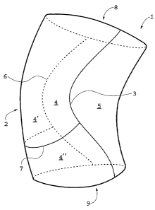
In fig. 1 reference numeral 1 concerns a joint protector
in the form of a knee protector for performing sports in the
form of a bent, tubular body made from a suitable flexible
material such as preferably a layer of porous neoprene rubber
laminated on each side with knitted textile material, or any
other material which per se is previously known with respect
to protectors of this kind.
Because of its curvature, the joint protector 1 has a
convex region 2 to be comfortably adapted to the extreme
portion of the joint, in this case the knee cap. The joint
protector according to the invention can also be used for
other joints such as elbows.
The joint protector 1 has a seam extending essentially
longitudinally between the first material portion 4 and the
second material portion S. The seam 3 between these material

portions extends along a curve in a manner which is to be
explained below, and which is made so that the first material
portion 4 is subjected to a contracting action for achieving


CA 02594303 2007-07-03
WO 2006/073353 PCT/SE2005/002065
6
the curved configuration of the tubular body. In the joint
protector 1 in fig. 1, the first material portion 4 belongs to
a first material piece and the other material portion 5 to a
second material piece. For this purpose the joint protector
also has a second seam 6, which is marked with an interrupted
line essentially longitudinally to the joint protector,
essentially on the opposite side to the seam 3. The seams 3
and 6 thus co-operate in order to achieve the curved
configuration of the joint protector. The "longitudinal
direction" or "axial direction" of the joint protector 1 is
defined as the direction between an upper opening at reference
numeral 8 and a lower opening at reference numeral 9.
In the joint protector 1 in fig. 1, the first material
piece which includes the first material portion 4 has two
parts, 4' and 4", which are joined together by means of a
further essentially transversal seam 7. Such a separation
could be arranged for aesthetic reasons or for practical
reasons, whereby in that case the parts 4' and 4" can be made
from different materials having different properties for
different parts of the protector. In its simplest form, the
joint protector is made without this seam 7 and the material
piece including the portion 4 consists of one single piece of
material.
An important aspect of a joint protector according to the
invention is to make it slightly narrowing in its central
portion that is having a slight "hour-glass shape". This gives
good adjustment to the joint and the widened shape of the
adjacent portions of arms and legs, so that a joint protector
is prevented from sliding from its correct position when the
joint articulates. The inventive joint protector gives good
possibilities of achieving a gently adapted curvature of the
joint protector in order to achieve such a central narrowing
without creasing and irregularities.


CA 02594303 2007-07-03
WO 2006/073353 PCT/SE2005/002065
7
In fig. 2 a blank of a joint protector according to the
invention is shown including two pieces of material, a first
piece of material including said first material portion 4 and
a second piece of material including said second material
portion S. For joining together these parts into a joint
protector, the parts are sewn together with a seam essentially
longitudinally of the completed joint protector between a
first edge 10 of the first material portion 4 and a second
edge 11 of the second material portion S.
As is shown in fig. 2, the first edge 10 extends along a
first curve defining a recessed area of material along an
essentially central portion of its extension, said recessed
area of material being indicated with A on the left part of
the, in this case, symmetrical piece of material.
The second edge 11 extends along a second curve which
defines an enlarged area of material, a, along an essentially
central part of its extension, said enlarged area of material
being limited at the right part of this piece of material with
an interrupted line.
As is shown in the figure the enlarged area of the
material, a, has a general tapering angle P which is smaller
than a general tapering angle a of the recessed area of
material. The curve S is thus shallower than the curve s. It
is preferred that (3 is about 10 -45 smaller than a.
The surface extension of the enlarged area of material,
a, is also smaller than the surface extension of the recessed
area of material, A. It is preferred that the surface
extension of the enlarged area of material is between 40% and
80% of the surface extension of the recessed area of material.
s is also shorter than S. The height h of the second
piece of material is also smaller than the height H of the
first piece of material. Altogether these parameters for
forming the different portions result in that a joining


CA 02594303 2007-07-03
WO 2006/073353 PCT/SE2005/002065
8
together of the first edge 10 with the second edge 11 will
result in a contracting action to the recessed area of
material, with or without tension provided between the two
portions, so that the completed protector will receive the
desired curved configuration. It is thus possible to join
together the protector in such a way that the edges 10 and 11
are essentially equally long and that thus no tensile tension
exists between the different parts. It is, however, preferred
that the second edge 11 in an unloaded state is shorter than

the first edge 10 in an unloaded state, whereby, when joining
by sewing, the shorter edge is subjected to a certain
stretching and the resulting seam distributes sideward tension
between the material portions that are sewn together. This
results in a good link between the material portions and
contributes to providing the joint protector with desired
properties. Preferably the blank parts are subjected to
different degrees of stretching and/or possibly contraction
along different portions of their extension, for example a
higher degree of stretching on non-central parts of the

material portion which is subjected to the stretching. This
can easily be marked by providing edges to be sewn together
with indexing points which are intended to coincide in
connection with the sewing.
It should be observed that with "blank" in this case also
is intended blanks being comprised of a plurality, e.g. two,
pieces of material.
In fig. 3 there is diagrammatically shown a joint
protector, wherein a first piece of material 4 completely
encloses a second piece of material 5, wherein the edges sewn
together by a seam 3 of said material portions 4 and 5 are
shaped according to what is described above in connection with
figs 1 and 2. In this case, however, the material portion 5
with its corresponding piece of material is completely


CA 02594303 2007-07-03
WO 2006/073353 PCT/SE2005/002065
9
enclosed by the piece of material of the material portion 4.
The reference numerals 12 and 13 concern seams for providing
the piece~of material including the material portion 4 a
tubular form. In this case the seam 3 is said contracting
seam. Also this can be defined to have at least portions which
extend longitudinally of the joint protector.
As an alternative a joint protector can of course be
contemplated, wherein a material portion 5 is enclosed at one
end of the joint protector, for example at the upper one, but

at the lower end of the joint protector extends according to
what is shown in fig. 1.
In fig. 4 is shown an integral blank in one single piece
which includes the first material portion 4 as well as the
second material portion S. In this case it could be
appropriate to provide cut-outs along the extension of the
blank, such as a transversal cut-out 21 and a longitudinal
cut-out,22 as seen in the "axial" direction of the completed
joint protector, which are sewed together in order to provide
a middle portion of the blank in fig. 4 with the desired
properties. Other shapes and positions of these cut-outs can
be envisaged.
In fig. 5 is diagrammatically shown a sequence concerning
a method for producing a joint protector according to the
invention, wherein position 15 indicates the start of the

sequence.
Position 16 concerns providing a first material portion
formed with a recessed area of material of an essentially
central part of the first edge.
Position 17 concern providing a second material portion
shaped with an enlarged area of material at an essentially
central part of the second edge.
Position 18 indicates bringing together the edges and
possibly stretching the edge of the second material portion.


CA 02594303 2007-07-03
WO 2006/073353 PCT/SE2005/002065
Position 19 concerns sewing together the edges of the
material portions, wherein the first material portion is
subjected to a contracting action of the recessed area of
material in order to obtain the curved configuration of a
5 resulting tubular body.
Position 20 indicates the end of the sequence.
Fig. 6 shows a joint protector according to a second
embodiment, wherein a first material portion 24 has a recessed
area of material 27 which is sewn together with an enlarged
10 area of material 28 of a second material portion 26. Further
this second material portion 26 has a recessed area of
material 29, which is sewn together with an enlarged area of
material 30 of a third material portion 25. Both seams of the
edges 27, 28 and 29, 30, respectively, are performed at
enlarged areas of material/recessed area of material, which
are formed as is described above in order in both cases that
the material portions are to be provided with a contracting
action through the seams of the recessed areas of material.
It is also possible to have a fourth material portion
sewn between the first and the third material portions and
providing an enlarged area of material sewn together with a
recessed area of material of the first material portion and a
recessed area of material sewn together with an enlarged area
of material of the third material portion, wherein all
recessed areas of material are provided with a contracting
action by the seams.
Through this embodiment, which is described in connection
with fig. 6, it is achieved a more distributed contracting
effect of the material pieces, whereby this effect can be said

to occur in two steps on each side of the protector where it
is applied. For each step the differences may be made smaller
between the meeting edges and still a considerable total
effect be obtained.


CA 02594303 2007-07-03
WO 2006/073353 PCT/SE2005/002065
11
The invention can be modified further within the scope of
the annexed claims. Thus, the shapes of the protectors as well
as the materials of the different portions may be varied. The
joint protector can thus include portions of non-elastic (but
flexible) properties. It is not excluded that further seams or
recesses can be supplied on different parts of the joint
protector, for example from aesthetic or practical reasons.
For best effect, the joint protector according to the
invention should include material having a stretching ability
exceeding about 25% and preferably over 30% and also up to and
exceeding 100%. This makes it possible to have good adaption
to the desired form and that further stretching resources
remain in order to make it possible for a joint which is
received by the joint protector to be optimally bent.


Representative Drawing
A single figure which represents the drawing illustrating the invention.
Administrative Status

For a clearer understanding of the status of the application/patent presented on this page, the site Disclaimer , as well as the definitions for Patent , Administrative Status , Maintenance Fee  and Payment History  should be consulted.

Administrative Status

Title Date
Forecasted Issue Date Unavailable
(86) PCT Filing Date 2005-12-30
(87) PCT Publication Date 2006-07-13
(85) National Entry 2007-07-03
Dead Application 2011-12-30

Abandonment History

Abandonment Date Reason Reinstatement Date
2007-12-31 FAILURE TO PAY APPLICATION MAINTENANCE FEE 2008-01-07
2009-12-30 FAILURE TO PAY APPLICATION MAINTENANCE FEE 2010-02-02
2010-12-30 FAILURE TO REQUEST EXAMINATION
2010-12-30 FAILURE TO PAY APPLICATION MAINTENANCE FEE

Payment History

Fee Type Anniversary Year Due Date Amount Paid Paid Date
Application Fee $400.00 2007-07-03
Registration of a document - section 124 $100.00 2007-10-31
Reinstatement: Failure to Pay Application Maintenance Fees $200.00 2008-01-07
Maintenance Fee - Application - New Act 2 2007-12-31 $100.00 2008-01-07
Maintenance Fee - Application - New Act 3 2008-12-30 $100.00 2008-12-17
Reinstatement: Failure to Pay Application Maintenance Fees $200.00 2010-02-02
Maintenance Fee - Application - New Act 4 2009-12-30 $100.00 2010-02-02
Owners on Record

Note: Records showing the ownership history in alphabetical order.

Current Owners on Record
OTTO BOCK SCANDINAVIA AB
Past Owners on Record
MAGNUSSON, STEFAN
Past Owners that do not appear in the "Owners on Record" listing will appear in other documentation within the application.
Documents

To view selected files, please enter reCAPTCHA code :


To view images, click a link in the Document Description column. To download the documents, select one or more checkboxes in the first column and then click the "Download Selected in PDF format (Zip Archive)" or the "Download Selected as Single PDF" button.

List of published and non-published patent-specific documents on the CPD .

If you have any difficulty accessing content, you can call the Client Service Centre at 1-866-997-1936 or send them an e-mail at CIPO Client Service Centre.


Document
Description 
Date
(yyyy-mm-dd) 
Number of pages   Size of Image (KB) 
Abstract 2007-07-03 2 68
Claims 2007-07-03 8 345
Drawings 2007-07-03 4 44
Description 2007-07-03 11 507
Representative Drawing 2007-09-21 1 4
Cover Page 2007-09-24 1 42
Assignment 2007-10-31 2 71
PCT 2007-07-03 3 95
Assignment 2007-07-03 2 83
Correspondence 2007-07-06 2 76
Correspondence 2007-09-20 1 27
Fees 2008-01-07 2 62
Fees 2010-02-02 2 62