Note: Descriptions are shown in the official language in which they were submitted.
CA 02594507 2011-05-18
-1-
ROLLER MILL
FIELD OF THE INVENTION
The invention relates to a roller mill, particularly for dressing ores.
Mills which are used in ore dressing must ensure a careful and gentle
comminution. The ground material must only be comminuted to the extent that
the
following processes for recovering the useful and valuable material of the ore
can be
performed as efficiently as possible. It is in particular necessary to avoid
fines,
because they have a negative effect on the following processes.
BACKGROUND OF THE INVENTION
DE 102 24 009 B4 discloses a shear-free comminution of ores, which uses a
LOESCH-type air-swept rolling mill. The transportation of the ground material
within
the grinding area and to the classifier, as well as to the downstream dust
separator
takes place with the aid of an air or gas flow, which flows into the grinding
area from
an annular duct located below the grinding bowl. As a result of the flow
direction from
bottom to top and therefore contrary to the force of gravity and the
geometrical
conditions with respect to the height of the grinding area or the distance
from the
classifying area, a correspondingly high kinetic energy must be available in
order to
ensure the pneumatic transport of the ground material particles. The energy
costs
increase if the size fraction to be transported includes larger ground
material particles.
Generally ore dressing requires a coarser size fraction than is required for
the
cement and power plant industry, where finenesses of e.g. 15% R 0.09 are usual
for
cement raw material or coal for the downstream burning processes. However, in
the
case of ores residual values of e.g. 20% R 0.212 are required. This leads to a
higher
energy demand for the gas flow, so that the known air-swept roller mills can
only be
used to a limited extent or not at all.
An improved energy balance in the area of particle transport can be obtained
if mechanical conveying replaces pneumatic conveying. The ground material fed
in the
centre of a grinding bowl and which moves outwards as a result of the
centrifugal force
CA 02594507 2011-05-18
-2-
and is comminuted in the grinding gap between the grinding rollers and
grinding
surface and then is discharged over the grinding bowl edge, drops into an
annular
clearance, which is formed by the rotating grinding bowl and a fixed
cylindrical
housing. Via inclined metal plates in a lower area of the mill the ground
material slides
to mechanical conveyors, which transport the ground material to separately set
up
classifying or screening devices, where the fine material is separated from
the coarse
material. The coarse material is again fed to the mill for further comminution
and up
to ten cycles are required for obtaining the desired particle size. The fine
material is
processed in downstream processes.
Such grinding cycles are performed with LOESCHE-type roller mills and are
also known in connection with mills of other types, e.g. roller presses (WO
99/54514
Al).
EP 1 247 580 A2 discloses a cyclic grinding device with a high pressure roller
mill and a classifier, which are positioned within two fixed side walls and an
intermediate, rotary mounted, rotation direction-displaceable material
conveying ring
for an internal grinding material cycle. In the area below the roller gap of
the roller mill
is provided a static cascade classifier with V-shaped baffle plates and
classifying air
is introduced through a feed mechanism housing in one of the side walls into
the area
below the roller mill. The static cascade classifier acts as a deagglomerator
for the
roller press scabs or shells. The classifying air containing fines is led out
over the side
walls, whereas the coarse material particles enter the rotary material
conveying ring
and are again supplied to the roller mill. A dynamic classifier can also be
positioned
downstream of the static cascade classifier. This equipment has a relatively
significant
overall height. Since with both the static and the dynamic classifier the side
walls of
the operating area form the classifying housing, there are also considerable
energy
costs.
GB 428 237 discloses a roller mill used for mixing materials and also for
comminuting, e.g. ores. The roller mill has, level with the grinding bowl, a
discharge
opening in the grinding area wall for the comminuted ground material. The
horizontal
ground material discharge takes place with the aid of fan blades positioned on
the
underside of the grinding bowl. The grinding process and the degree of
comminution
CA 02594507 2011-05-18
-3-
are determined by the construction of the housing closely adjacent to the
grinding bowl
or the grinding area wall, the horizontal discharge opening, the adjustable
fan blades
and vertical deflectors positioned between the grinding rollers. An
alternatively
constructed mill has, in addition to the horizontal discharge opening, further
openings
below the grinding bowl. Into the latter pass the comminuted material which
has
dropped over the grinding bowl edge and into the annular clearance between the
grinding bowl and the lower mill part and it is then mechanically supplied or
supplied
with the aid of blowers to the further treatment process.
The present invention provides a roller mill wherein there is no need for a
mechanical or pneumatic transport of the comminuted ground material to a
classifying
or screening system and the desired size fraction can be obtained with
relatively
limited energy expenditure.
SUMMARY OF THE INVENTION
As an aspect of the present invention, there is provided a roller mill
comprising
a rotary grinding bowl having a grinding bowl edge, a grinding area wall
surrounding
the rotary grinding bowl, grinding rollers rolling on the rotary grinding
bowl, an annular
area which is bounded by the grinding bowl edge and the grinding area wall, at
least
one discharge opening in the annular area for discharge of comminuted ground
material comminuted between the grinding rollers and the grinding bowl, an
annular
chamber for the supply of a classifying air flow, and an integrated
classifying device
located below the grinding bowl edge, wherein the classifying device receives
the
comminuted ground material by gravity from the at least one discharge opening,
is
connected with the annular chamber, and has at least one fine material outlet
and a
coarse material outlet.
It is a fundamental concept of the invention to provide below the grinding
area
a classifying device, in which the comminuted ground material comminuted on
the
grinding bowl and which has dropped downwards over the edge of said bowl as a
result of gravity undergoes classification and is separated into a fine and a
coarse
material fraction.
CA 02594507 2011-05-18
-4-
Classifying takes place with the aid of a gas or air flow, referred to
hereinafter
as the classifying air flow, which is supplied to the classifying device by
means of a
lower annular chamber and is discharged containing fines. The coarser ground
material particles pass out of the classifying device via a coarse material
outlet and
said device is integrated into the roller mill for a "down classification".
An energy saving results from this, because there is no need for a conveying
of the comminuted ground material to a classifier or to a screening system
outside the
mill. Additionally no kinetic energy is necessary, because the fall energy of
the ground
material particles discharged over the grinding bowl edge is utilized.
It is advantageous that the classifying device and the annular chamber are
arranged cylindrically around a lower area of the grinding bowl and there are
at least
one inlet opening for the classifying air flow and at least one fine material
outlet and
one coarse material outlet in the annular chamber or classifying device wall.
The classifying device below the grinding area can be constructed for static
and/or dynamic classification. For example, dynamic classifying rotors can be
positioned in the vicinity of the annular area and have a horizontal or
vertical rotation
axis.
It is advantageous to use a static classifying device constructed as a
Venetian
blind or jalousie classifier and which is equipped with sloping, overlapping
blades. Said
jalousie classifiers can be operated with a relatively high dust
concentration. In that
less gas is required relative to the ground material, a further energy saving
is achieved.
Appropriately the blades of the classifying device constructed in jalousie or
louvre manner are oriented in downwardly sloping and outward manner. The
ground
material discharged over the grinding bowl edge and which under the influence
of the
free fall energy drops into the classifying device, strikes the overlapping
blades, so that
the mass flow is decelerated on impacting on each blade and as a result of the
slope
is passed over the edge to the next blade. The introduced classifying air flow
flows
through the jalousie and the ground material curtain. The finer particles are
deflected
outwards and leave the classifying device with the classifying air flow
through the fine
material outlet. The coarser particles drop downwards towards the coarse
material
outlet, which is located in a bottom area of the classifier wall.
CA 02594507 2011-05-18
It is advantageous that the size of the particles deflected to the fine
material
outlet can be influenced by the gas quantity and the resulting speeds between
the
blades. If the fine material-gas flow is subject to a deflection of e.g.
approximately
90° following the blades, an additional separation effect is achieved.
In order to ensure that classifying air or gas cannot enter the annular and
grinding area in opposition to the downwardly falling, comminuted ground
material,
cover elements are provided and are able to bound and limit the annular area
opening
axially and/or in ring segment-like manner and fulfil a sealing function.
Appropriately
the cover elements are constructed as flaps or ring segments and bound the
annular
area opening in such a way that it is completely filled by the ground material
flow
discharged over the grinding bowl edge. The cover elements are appropriately
adjustable and in particular pivotable about a horizontal axis and fixed to
the grinding
area wall.
LOESCHE-type, modular roller mills which have grinding rollers separately
supported and pivotably mounted on mill standards are equipped with a
classifying
device, which in each case has classifying areas between the standards. In
each
classifying area is coaxially and externally provided a fine material outlet,
e.g. a
connecting piece, and at the bottom a coarse material outlet and the bringing
together
thereof takes place outside the mill.
The annular chamber in the lower area of the grinding bowl completely
surrounds the latter, the seal with respect to the rotary grinding bowl being
provided
by a gland or labyrinth packing or gap sealing.
In the areas of the mill standards, between the individual classifying areas,
which can advantageously be constructed as louvres or jalousies, is provided a
cylindrical part or a part cylindrical connecting wall, which extends into the
upper area
of the grinding bowl and is e.g. here sealed by a gland or gap sealing.
To deflect the comminuted ground material discharged by the grinding bowl into
the classifying areas between the mill standards there are baffle plates below
the
grinding rollers in the annular area between the grinding bowl and the
grinding area
wall. In the upper area said baffle plates have a roof-shaped construction and
are
supported on vertical baffle plates. Fixing can occur on the vertical
connecting wall.
CA 02594507 2011-05-18
-6-
BRIEF DESCRIPTION OF THE DRAWINGS
The invention is described in greater detail hereinafter relative to the
attached
diagrammatic drawings, wherein show:
Fig. 1 A detail longitudinal section through an inventive roller mill with
integrated
classifying device below the grinding area.
Fig. 2 A perspective view of the classifying device for a modular roller mill
with
four grinding rollers/mill standards.
DETAILED DESCRIPTION OF THE PREFERRED EMBODIMENT
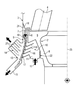
Fig. 1 is a longitudinal section through the left-hand side of a roller mill
in the
vicinity of a grinding roller 4, which rolls on a grinding bowl 2. Grinding
bowl 2 rotates
about a rotation axis 25 and the ground material 7 comminuted in a grinding
gap
between the grinding roller 4 and the grinding bowl 2 passes over the grinding
bowl
edge 6 into an annular area 5. The annular area 5 is bounded by the grinding
bowl
edge 6 and a grinding area wall 3, which is substantially vertically oriented.
In the
upwards direction the grinding area can have a not shown cover and a dust
removal
device can also be provided. However, the mill can also be operated in an open
air
process.
A classifying device 10 to which classifying air flow 12 is supplied via an
annular
chamber 11 is positioned below the grinding bowl edge 6 and annular area 5.
In the present embodiment the classifying device 10 is a static louvre-type
classifier or jalousie classifier, which has sloping, overlapping blades 16.
The classifying device 10 with the blades 16 is positioned in such a way that
the
comminuted ground material 7, which drops downwards solely as a result of fall
energy over the grinding bowl edge 6 and annular area 5, strikes the
individual blades
16, is decelerated and classified with the aid of the classifying air flow 12
passing
through the blades 16. The fine material separated from the coarse material
passes
with the classifying air outwards through a fine material outlet 14, which
extends over
virtually the entire height of the classifying device 10 and coaxially thereto
in an outer
wall 13, whereas the coarse material is discharged via a coarse material
outlet 5 in a
bottom wall 17 of the classifying device 10.
CA 02594507 2011-05-18
-7-
Fig. 1 makes it clear that the fine material outlet is so positioned in the
outer
wall 13 that the fine material-containing classifying air undergoes a
deflection, which
leads to an additional separation effect. A removal of any still entrained
coarse
particles can also be brought about by guide plates 27, which are located in
the fine
material outlet 14. FIG. 1 also shows that the bottom wall 17, which is
bounded on the
inside by the annular chamber 11 and on the outside by the coarse material
outlet 15,
has the same inclination as the blades 16 of the classifying device 10.
In the annular area 5 cover elements 18 are pivotably fixed to the grinding
area
wall 3, which prevent classifying air 12 from passing via the annular area 5
into the
grinding area and acting against the downwardly falling, comminuted ground
material
7. The two positions of the cover elements 18 shown in Fig. 1 are of an
exemplified
nature and can also be provided in alternative form. The cover element 17 can
be
pivoted in such a way that the annular area 5 has an opening completely filled
by the
comminuted ground material flow.
The annular chamber 11 which extends in a lower area 8 of the grinding bowl
2 around the latter, has a gland/labyrinth packing or gap sealing 22 with
respect to the
grinding bowl 2. The grinding area wall 3 can in the vicinity of the grinding
bowl edge
6 be constructed as a baffle 24 and can be provided with a not shown, wear-
resistant
lining.
Fig. 2 perspectively shows a classifying device 10, which is constructed for
installation below the grinding bowl of a LOESCHE-type, modular, roller mill.
The
classifying device 10 is provided with classifying areas 20, which are located
between
the not shown mill standards. The annular chamber 11, into which the
classifying air
or gas 12 is introduced, surrounds the grinding bowl 2 (see Fig. 1) in a lower
area in
a complete manner. In Fig. 2 the classifying areas 20 are once again blades
with
outwardly and downwardly inclined blades 16, in the vicinity of which are
externally
provided connecting pieces as the fine material outlet 14 in outer housing 13
(see Fig.
1).
In the areas 23 of the not shown mill standards, i.e. below the grinding
rollers
4 (see Fig. 1), are provided between the classifying areas 20 in the form of
an outer
boundary part cylindrical connecting walls 19 which are positioned vertically,
extending
CA 02594507 2011-05-18
-8-
into the upper area (9) of the grinding bowl 2 (see Fig. 1) and are here
sealed with
respect to the rotary bowl by means of a not shown gland. To ensure that the
comminuted ground material 7 discharged from the grinding bowl enters the
classifying
areas 20, baffle plates 21 are vertically oriented and arranged in the form of
a roof
slope 26 are fixed to the associated connecting wall 19. The blades 16 of the
classifying areas 20 in each case extend up to the vertically positioned
baffle plates
21.