Note: Descriptions are shown in the official language in which they were submitted.
CA 02594984 2007-07-16
DESCRIPTION
SUPPORT STRUCTURE OF BUILDING
TECHNICAL FIELD
[0001] The present invention relates to a support structure of buildings, in
which. while securing axis of each support used in buildingti, its outer
diameter
can be set at any size.
BACKGROUND ART
[0002] As is generally known, a wooden support of large buildings, such as
houses and ships, is one formed by a so-called one-piece, large-diameter, log
member shaped by bringing down a large tree, or is produced by subjecting
many wood chips of timber into a compression molding into a pillar that is one-
piece having a predetermined outer diameter.
Patent Publication 1: Japanese Patent Application Publication 2000-265552
and the like.
DISCLOSURE OF THE INVENTION
TASK TO BE SOLVED BY THE INVENTION
[0003] However, of the above-mentioned conventional support structures of
building, for example, one formed of a log member is naturally limited in its
outer diameter. Therefore, in the case of using them for a large building,
many
supports are necessary in order to secure strength. As a result, it is likely
that
the interior space is limited.
On the other hand, in the above-mentioned one formed by compressing
wood chips, an axis as that of support is not secured. It is thus not possible
to
obtain a sufficient strength. Therefore, it is not possible to apply it to a
large
building.
The present invention was made in view of technical problems of the
above-mentioned conventional support structures of building. Its object is to
provide a support structure that is capable of freely setting the size of
outer
1
CA 02594984 2007-07-16
diameter, while securing axis of support and thereby obtaining a sufficient
strength.
MEANS FOR SOLVING TASK
[0004] The invention according to claim 1 is characterized in that a central
support section having a rectangular cross-section is arranged at a central
position and that a plurality of winding support sections of a substantially
elongat.e plat.elike shape are combined and arranged around the central
support section, while being sequentially spirally wound from a longitudinal
direction, thereby fixing each support section under a laminated condition
between inside and outside and setting an overall outer diameter at any size.
[0005] According to this invention, a support is constructed by arranging and
fixing each winding support section around at least one central support
section
in a spiral manner like annual rings of a log. Therefore, the central support
section becomes an axis, and each winding support section also functions as a
core member. Thus, it is possible to have a sufficient compression strength of
the entirety in the axial direction (longitudinal direction). Furthermore,
each
winding support section is spirally and organically attached. Therefore, it is
also possible to sufficiently have rigidity in lateral direction. As a result,
it is
possible to prevent a deformation caused by drying, and it can be formed by
using timber from forest-thinning.
[0006] It is possible to freely set the overall outer diameter by the amount
of
the assembly of each winding support section. Therefore, it can be applied to
any building irrespective of small buildings and large buildings. In
particular,
it can also be applied in this invention to a large building that cannot be
met
by an ordinary log. Therefore, it is possible to decrease its number to be
applied to building in cooperation with high strength in the above-mentioned
axial direction and the like. Thus, it becomes possible to have a large
interior
space, etc. .
[0007] The invention according to claim 2 is characterized in that three of
the
winding support sections on the same circumference are formed to have widths
that are substantially the same, the other winding support section is formed
to
2
CA 02594984 2007-07-16
have a width that is longer by a plate thickness that is then wound around the
periphery, and each winding support section is combined and arranged while it
is sequentially spirally wound.
[0008] According to this invention, it is not that each winding support
section
of the same width is simply attached from the outside, but one winding
support section is set at a length that is the same as the thickness of the
winding support section wound next. With this, it is possible to spirally and
continuously connect each winding support section. Therefore, a connecting
strength between each winding support section becomes large. As a result, the
entirety of the support becomes high in rigidity and strength, and it can
sufficiently be applied to a large building.
[0009] The inventions according to claims 3 and 4 are characterized in that a
plurality of support units, each being combined by sequentially spirally
winding a plurality of winding support sections around the central support
section, are combined and fixed with each other to an assembled condition,
thereby constituting one support.
[0010] According to these inventions, one support is formed by combining
together a plurality of support unit bodies. Therefore, it is possible to
freely
set the size of the support. Furthermore, it becomes possible to further
improve strength in the axial direction since one support can be formed with a
plurality of central support sections.
[0011] The inventions according to claims 5 to 7 are characterized in that the
central support section and the winding support sections are formed to be able
to freely set their lengths in the axial direction.
[0012] According to these inventions, it is possible that the central support
section and each winding support section are previously set at predetermined
lengths and that, while extending these to conform to a building, these are
freely stretched in the axiaJ direction.
[0013] The inventions according to claims 8 and 9 are characterized in that,
when each winding support section is spirally assembled from the central
support section, the length of each support section in the axial direction is
3
CA 02594984 2007-07-16
sequentially spirally changed as the winding support sections are wound
outside from the central support section, and a plurality of support units,
each
comprising the central support section and the winding support sections, are
connected together in the axial direction.
[0014] The invention according to claim 10 is characterized in that, when each
winding-side support unit to be wound around the central support unit is
spirally assembled, the length of each support unit in the axial direction is
sequentially spirally changed as the winding-side support units are wound
outside from the central support unit, and a plurality of support unit groups,
1.0 each comprising the central support unit and the winding support units,
are
connected together in the axial direction.
[0015] According to the inventions of claims 8-10, for example, the winding
support sections (the winding-side support units) are sequentially assembled
from the central support section (the central side support unit) in a manner
to
have spiral steps in the axial direction. Therefore, it is possible to
assemble
support sections and support units, which are positioned above and below, into
a fitted condition, thereby increasing each adhesion area. As a result,
adhesion strengths of upper and lower support units and support unit groups
are further improved, and strengths in the axial direction and in the
diametral
direction are also improved.
[0016] Furthermore, a single support can finally be formed, for example, only
by previously setting each support section at the same length, then assembling
it spirally, then connecting these support units from the vertical directions,
and then cutting the upper and lower end portions. Therefore, yield of the
material improves.
[0017] The invention according to claim 11 is an invention of a support
assembly method. It is characterized in that it comprises a first step of
arranging a central support section having a rectangular cross-section at an
axial central position; a second step of combining and arranging a plurality
of
winding support sections of a substantially elongate platelike shape around
the central support section, while being sequentially spirally wound, and
4
CA 02594984 2007-07-16
adhering inner and outer surfaces of each winding support section, and a third
step of cutting away an end portion of the final winding support section,
which
projects from an outer side surface of another winding support section, after
termination of the winding.
[0018] According to this invention, it is only necessary to sequentially
spirally
assemble and fix each winding support section relative to the central support
section. Therefore, such assembly operation is eas~~.
BRIEF DESCRIPTION OF THE DRAWINGS
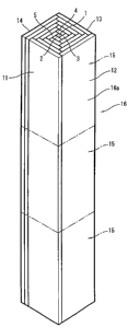
[0019] Fig. 1 is a plan view showing a first embodiment of a support structure
according to the present invention;
Fig. 2 is a perspective view showing a condition in which each support
unit of the present embodiment is connected from the vertical direction;
Fig. 3 is a perspective view showing a square pillar formed finally of
the present embodiment;
Fig. 4 is a plan view showing a second embodiment of the present
invention;
Fig. 5 is a plan view showing a third embodiment of the present
invention; and
Fig. 6 is a perspective view showing a condition in which each support
unit group in the third embodiment is connected from the vertical direction.
BEST MODE FOR CARRYING OUT THE INVENTION
[0020] In the following, embodiments of the support structure of building
according to the present invention are described in detail, based on drawings.
[0021] Fig. 1 to Fig. 4 show the first embodiment of the present invention.
This support structure is constituted of a wooden central support section 1
disposed at a central position and a plurality of wooden winding support
sections 2, 3, 4, 5..., which are spirally windingly disposed at a periphery
of the
central support section 1. ,
[0022] The central support section 1 is formed of a pillar having a
substantially square cross-section, and its length in the axial direction is
freely
set.
5
CA 02594984 2007-07-16
[0023] The above-mentioned plurality of winding support sections 2, 3, 4, 5...
are each formed of pillars that are substantially rectangular in cross-
section,
and their lengths in the axial direction are set to be the same as the length
of
the central,support section 1. The thickness S of each winding support section
is set to be the same, and the width W1 thereof is set at a size double,
triple...
in sequence as they are wound outwardly from the central side.
[0024] In other words, at first, the four winding support sections -9, 3, 4, 5
are
spirally disposed on and bonded to four peripheral surfaces la of the central
support section 1 with adhesive B. Of these, the three winding support
sections 2, 3, 4 are set at a width Wl that is two times the width W of the
central support section. Of the other winding support section 5, an end
portion
5a is set to be longer by the thickness S of the winding support sections 6,
7, 8,
9, which are next wound around the periphery.
[0025] Furthermore, of the next three winding support sections 6-8, which are
wound on the peripheral surfaces of winding support sections 2-5, the width
W2 is set at a size three times the central support section 1. Of the other
winding support section 9, an end portion 9a is set to be longer by the
thickness S of the next winding support section.
[0026] As mentioned above, of the winding support sections 2-5, 6-9, ...,
which
are sequentially wound outside from the central support section 1, the width
Wn of the three is set to be larger double again and again relative to the
width
W of the central support section 1, and the other one is set to be larger by
the
thickness S of the winding support section wound on this peripheral side.
[0027] The length of each winding support section 2-9... in the axial
direction
is set at a length that is substantially the same as that of the central
support
section 1. In other words, it is set at any length.
[0028] As a method for assembling each winding support section 2-9..., each
winding support,section 2-4 of the onefold is assembled by aligning two
timbers having the same width as that of the central support section and then
by bonding them together by adhesive from the lateral direction. Furthermore,
each of the other winding support section 5 and the winding support sections
6
CA 02594984 2007-07-16
6-8 of the twofold is assembled by aligning three timbers having the same
width as that of the central support section and then by bonding them together
by adhesive under this condition. Similarly, each winding support section of
the threefold or further is assembled by making timbers having the same
width as that of the central support section 1 double again and again and then
by bonding them together in parallel condition.
[0029] The winding support sections 2-5, 6-9... are spirally Nveund fivefold
at
last around the central support section 1. Each winding support section is
strongly bonded at its inside and outside surfaces by adhesive B.
[00301 As shown in Fig. 2, when each winding support section 2-9...is spirally
assembled from this central support section 1, the length of each support
section 1-9... in the axial direction is sequentially spirally changed as the
winding support sections 2-9... are wound outside from the central support
section 1. A plurality of support unit bodies 15, 15..., each being formed of
the
central support section 1 and the winding support sections 2-9..., are
connected
into a fitted condition from the vertical directions. Upon this, support
sections
1-9 of the upper and lower support unit bodies are bonded with each other by
adhesive B. In Fig. 2, only the winding support sections 2-9 are shown by
omitting the winding support sections that are shown in Fig. 1 and are further
wound around the periphery of the winding support sections 6-9.
[0031] As shown in Fig. 1, of the four winding support sections 11-14 wound at
last in the winding support sections 2...wound to have predetermined sizes, an
end portion 14a of the winding support section 14, which is long by the
thickness of S,.is cut off.
[0032] In case that the support sections 1-9 are assembled spirally to have
steps as mentioned hereinabove and the support unit bodies 15 are connected
together into a fitted condition from vertical directions to make the whole
have
a predetermined length at last, the upper end portion projects upward and the
lower end portion is in a concave form by the spiral form of the support
sections 1-9... Therefore, each of these projection portion l0a and concave
portion l0a is cut off.
7
CA 02594984 2007-07-16
[0033] With this, as shown in Fig. 3, a single square pillar (support) having
a
desired length and a relatively large cross-section is formed.
[0034] Then, it is possible to form a smooth surface by subjecting the
entirety
of the surface 16a of this square pillar 16 to machining. In some cases, it is
also possible to subject the surface 16a to carving and painting after
machining to produce a decorated pillar. It is also possible to form a round
pillar having a circular cross-section by cutting off the corner portions of
the
square pillar 16 as shown by a dash double-dotted line of Fig. 1. After
conducting a surface treatment of the square pillar 16, it is used as a pillar
of a
predetermined building.
[0035] As mentioned hereinabove, according to a support structure of the
present embodiment, a square pillar 16 is constructed by arranging and fixing
each winding support section 2-14... around at least one central support
section 1 in a spiral manner like annual rings of a log. Therefore, the
central
support section 1 becomes an axis, and each winding support section 2-14...
also functions as a core member. Thus, it is possible to have a sufficient
compression strength of the entirety in the axial direction (longitudinal
direction). Furthermore, each winding support section is spirally and
organically attached. Therefore, it is also possible to sufficiently have
rigidity
in lateral direction.
[0036] As a result, it is possible to prevent a deformation caused by drying,
and it can be formed by using timber from forest-thinning.
[0037] It is possible to freely set the outer diameter of the entirety of the
square pillar 16 (round pillar) by the amount of the assembly of each winding
support section 2-14.... Therefore, it can be applied to any building
irrespective of small buildings and large buildings. In particular, it can
also be
applied to a large building that cannot be met by an ordinary log. Therefore,
it
is possible to decrease its number to be applied to building in cooperation
with
high strength in the above-mentioned axial direction and the like. Thus, it
becomes possible to have a large interior space and the like.
8
CA 02594984 2007-07-16
[0038] It is not that each winding support section 2...14... of the same width
is
simply attached from the outside, but one winding support section 5, 9...141s
set at a length that is the same as the thickness S of the winding support
section wound next. With this, it is possible to spirally and continuously
connect each winding support section 2-14.... Therefore, a connecting strength
between the central support section 1 and each winding support section 2-14...
becomes large.
[0039] As a result, the entirety of the square pillar (support) becomes high
in
rigidity and strength, and it can sufficiently be applied to a large building.
[0040] According to this embodiment, it only necessary to sequentially
spirally
assemble and fix each winding support section 2 relative to the central
support
section 1. Therefore, the assembly operation is easy.
[0041] Furthermore, according to this embodiment, as mentioned above, when
the winding support sections 2-14 are assembled while winding them from the
central support section 1, the support sections 1-14 are sequentially
assembled
in a manner to have spiral steps in the axial direction. Therefore, in case
that
the support unit bodies are connected together from the axial direction, it is
possible to assemble each support section 1-14, which are positioned above and
below, into a fitted condition, thereby increasing each adhesion area.
[0042] As a result, adhesion strength of the upper and lower support unit
bodies 15 are further improved, and strengths in the axial direction and in
the
diametral direction are also improved.
[0043] Furthermore, a single square pillar 16 can finally be formed only by
previously setting each support section 1-14 to have the same length, then
assembling it spirally, then connecting these support unit bodies 15 from the
vertical directions, and then cutting the upper and lower end portions 10a,
lOb.
Therefore, yield of the material improves.
[0044] Furthermore, according to this embodiment, in order to form each
winding support section 2-9... as mentioned above, square timbers having the
same length as that of the central support section 1 are used, and these are
connected in parallel, while sequentially increasing these, to form respective
9
CA 02594984 2007-07-16
ones. Therefore, yield of the material further improves, and it is possible to
lower the cost.
[0045] Fig. 4 shows a second embodiment of the present invention. A central
support section 21 is formed to have an almost square cross-section, which is
the same as that of the first embodiment. However, the thicknesses S1... of
the winding support sections 22... are set to be sequentially larger as it
goes to
the peripheral side.
[0046] That is, the width W1 of each winding support section 22-25, which is
wound and arranged on a peripheral surface 21a of the central support section
21, is set at about two times that of the central support section 21, and its
thickness S1 is set to be almost the same as the width S of the central
support
section 21. The thickness S2 of each winding support section 26-29 of the
twofold, which is wound and arranged on each peripheral surface of each
winding support section 22-25 of the onefold, is set at 1.5 times that of the
winding support section 22-25. Therefore, an end portion 25a of the last
winding support section 25 of the onefold is set at a length projecting by the
thickness S2 of the twofold.
[0047] The thickness S3 of the winding support sections 30-33 of the threefold
is set at a size that is 1.75 times that of the twofold. Therefore, an end
portion
29a of the last winding support section 29 of the twofold is also set at a
length
projecting by the thickness S3 of the threefold.
[0048] Furthermore, the thickness S4 of the winding support sections 34-37 of
the fourfold is set at a thickness that is 1.8 times that of the threefold.
Therefore, an end portion 37a of the last winding support section 37 of the
threefold is set at a length projecting by the thickness S4 of the fourfold.
[0049] In such manner, the thickness Sn of the winding support sections 22-37
is set to be sequentially larger as it goes to the peripheral side, and an end
portion of the last winding support section of each fold is formed to project
by
the thickness of the peripheral side.
[0050] Similar to the first embodiment, the outer surface 21a of the central
support section 21 and the inner and outer surfaces of each winding support
CA 02594984 2007-07-16
section 22... are strongly bonded together by adhesive B, and its length in
the
axial length is freely set depending on the size of building or the like.
[0051] Therefore, according to this embodiment, provided that the outer
diameter of a square pillar 38 formed by each support section 21, 22... is the
same, it becomes possible to lower the number of the winding support sections
22... as compared with the case of the first embodiment.
[0052] After forming into the single square pillar 38, similar to the first
embodiment, it is possible to form a decorated pillar by suitably putting
carving and painting after surface treatment or to form a round pillar as
shown by a dash double-dotted line of Fig. 4.
[0053] Fig. 5 shows a third embodiment of the present invention. For example,
the square pillar 16 formed by the first embodiment is used as a single
support
unit body 40, and these 9 support unit bodies 40... are combined and bonded to
each other, thereby forming a square pillar 42.
[0054] Also in this embodiment, similar to the first and second embodiments,
as shown in Fig. 6, when each support unit body 40 was outside wound and
assembled from the central support unit body 40, the length of each support
unit body 40 in the axial direction was sequentially spirally changed to have
steps, and a plurality of support unit groups 41 formed of the central support
unit body 40 and the support unit bodies 40 on the winding side were
connected from the axial directions. The length of each support unit body
40...
in the axial direction is set to be almost the same.
[0055] Therefore, according to this embodiment, since a single square pillar
42
is formed by combining a plurality of the support unit bodies 40, it is
possible
to freely set the size of the square pillar 42. Furthermore, since it is
possible to
form a plurality of the central support sections 1...in a single square pillar
42,
it becomes possible to further increase compression strength in the axial
direction. 9
[0056] Furthermore, as mentioned above, a single square pillar 42 is formed
by spirally winding each support unit body 40... and then by connecting a
plurality of support unit groups 41 from vertical directions. Therefore,
similar
11
CA 02594984 2007-07-16
to the first and second embodiments, bonding strength in vertical directions
becomes higher, and yield of the material becomes good.
[0057] The present invention is not limited to each of the above embodiments.
For example, it is also possible to make the number of the winding support
sections less by setting the outer diameter of the central support section to
a
relatively large one. Furthermore, it is also possible to freely set the width
and
the thickness of each winding support section in accordance with the outer
diameter of the support, etc.
[0058] Furthermore, for example, it is naturally possible to previously
process
the winding support sections 2-14 in the first embodiment into ones of sizes
having respective widths without connecting ones of the central support
section 1 in parallel.
[0059] Although wood was used in each embodiment, it is also possible to form
the central support section with wood and the winding support sections with
another material, for example, high-hardness synthetic resin material, etc.
12