Language selection

Search

Patent 2595002 Summary

Third-party information liability

Some of the information on this Web page has been provided by external sources. The Government of Canada is not responsible for the accuracy, reliability or currency of the information supplied by external sources. Users wishing to rely upon this information should consult directly with the source of the information. Content provided by external sources is not subject to official languages, privacy and accessibility requirements.

Claims and Abstract availability

Any discrepancies in the text and image of the Claims and Abstract are due to differing posting times. Text of the Claims and Abstract are posted:

  • At the time the application is open to public inspection;
  • At the time of issue of the patent (grant).
(12) Patent: (11) CA 2595002
(54) English Title: MILL LINER ASSEMBLY
(54) French Title: ASSEMBLAGE DE DOUBLURE DE MOULIN
Status: Granted and Issued
Bibliographic Data
(51) International Patent Classification (IPC):
  • B02C 17/22 (2006.01)
(72) Inventors :
  • ABARCA MELO, RICARDO (Chile)
  • FERNANDEZ DABERTI, RICARDO (Chile)
(73) Owners :
  • VULCO S.A.
(71) Applicants :
  • VULCO S.A. (Chile)
(74) Agent: MOFFAT & CO.
(74) Associate agent:
(45) Issued: 2014-12-30
(86) PCT Filing Date: 2006-01-16
(87) Open to Public Inspection: 2006-07-27
Examination requested: 2010-11-01
Availability of licence: N/A
Dedicated to the Public: N/A
(25) Language of filing: English

Patent Cooperation Treaty (PCT): Yes
(86) PCT Filing Number: PCT/AU2006/000049
(87) International Publication Number: AU2006000049
(85) National Entry: 2007-07-16

(30) Application Priority Data:
Application No. Country/Territory Date
0102-2005 (Chile) 2005-01-18

Abstracts

English Abstract


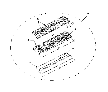
A liner assembly for use in a grinding mill, the liner assembly including a
liner body including
a mounting member, and an elastomeric cushioning member operatively connected
to the
mounting member. The cushioning member includes a plurality of support
cavities therein,
and a plurality of wear elements mounted within the support cavities.


French Abstract

Assemblage de doublure pour une utilisation dans un broyeur, l~assemblage de doublure comprenant un corps de doublure comprenant un élément de montage, et un élément amortisseur élastomérique connecté de manière opérationnelle à l~élément de montage. L~élément amortisseur comprend une pluralité de cavités de soutien dans celui-ci et une pluralité d~éléments d~usure montée dans les cavités de soutien.

Claims

Note: Claims are shown in the official language in which they were submitted.


7
CLAIMS:
1. A grinding mill having a rotatable drum with an inner surface and a liner
system
positioned on the inner surface of the rotatable drum, the liner system
further comprising
a plurality of lifter bars extending generally in the same direction as the
axis of rotation of
the drum and being circumferentially spaced apart around the inner surface of
the drum
so as to form channels between adjacently spaced lifter bars, and a plurality
of liner
assemblies, each liner assembly further comprising:
a mounting member for securing the liner assembly to the inner surface of the
rotatable drum, the mounting member having a surface for receiving an
elastomeric cushioning member;
an elastomeric cushioning member of selected hardness having a base wall
operatively connected to the mounting member, opposed side walls, extending
a distance K away from the base wall, which terminate at an outer edge, and
an outer wall extending between the outer edges of the opposed side walls to
define an outermost region of the outer wall, where the outermost region
extends away from said base wall a distance which is greater than the distance
K:
a plurality of support cavities formed in the outermost region of said outer
wall of
said elastomeric cushioning member: and
a plurality of wear elements having a selected hardness greater than said
hardness
of said elastomeric cushioning member, each support cavity having one of
said wear elements mounted therein to provide wear elements in said
outermost region of said outermost wall that are positioned to extend inwardly
toward the rotational axis of the rotatable drum,
wherein said liner assembly is disposed within respective channels formed
between said spaced apart lifter bars, with the mounting members secured to
the inner surface of the drum.
2. A liner assembly for use in a grinding mill having a rotatable drum with an
inner
surface oriented toward a rotational axis about which the rotatable drum
rotates, the liner

8
assembly comprising a mounting member which is structured to be operatively
secured to
the inner surface of the rotatable drum, an elastomeric cushioning member
having a base
wall operatively connected to the mounting member, opposed side walls
extending away
.from the base wall which terminate at an outer edge and a convex outer wall
extending
between the outer edge of one side wall to the outer edge of said other side
wall and
positioned for orientation toward the rotational axis of the rotatable drum, a
plurality of
support cavities formed in the outer wall of said elastomeric cushioning
member, and a
plurality of wear elements, each support cavity of said elastomeric cushioning
member
having one of said wear elements mounted therein, wherein the wear elements
have a
hardness that is measurably harder than a hardness of said elastomeric
cushioning
member and the wear elements provide a wear surface substantially over the
whole outer
wall.
3. A liner assembly for use in a grinding mill having a rotatable drum with an
inner
surface. the liner assembly, comprising:
a mounting member having a first surface for operative securement to the inner
surface of a grinding mill drum and having a second, opposing surface for
receiving an elastomeric cushioning member;
an elastomeric cushioning member having a base wall operatively connected to
the mounting member and having opposed side walls that each extend a
distance K from said base wall to terminate at an outer edge, and an outer
wall, extending between said outer edge of one said opposed side wall to said
outer edge of the other opposed side wall and extending away from said base
wall a distance which is greater than the distance K to thereby define an
outermost region of said outer wall;
a plurality of support cavities formed in the outer wall of said elastomeric
cushioning member and said outermost region of said elastomeric cushioning
member; and
a plurality of wear elements, each support cavity of said elastomeric
cushioning
member having one of said plurality of wear elements positioned therein to

9
provide wear elements that extend beyond the distance K of said opposed side
walls,
wherein the wear elements have a hardness that is measurably harder than a
hardness of said elastomeric cushioning member and the wear elements
provide a wear surface substantially over the whole outer wall including said
outermost region.
4. The liner assembly according to claim 3 wherein said elastomeric cushioning
member
is an elongated body and said plurality of support cavities are arranged in
one or more
rows extending in the direction of the longitudinal axis of the elongated
body.
5. The liner assembly according to claim 4 wherein there is provided two or
more rows of
support cavities arranged side by side.
6. The liner assembly according to claim 5. wherein said plurality of support
cavities in
one row are offset with respect to the plurality of support cavities in an
adjacent row.
7. The liner assembly according to any one of claims 3 to 6, wherein the
length of the
elastomeric cushioning member is between 2 to 12 times the width of the
cushioning
member.
8. The liner assembly according to any one of claims 3 to 7, wherein a
distance M
measured from said outer edge of each opposed side wall to an outermost region
of the
outer wall is about 1 to 40 cm.
9. The liner assembly according to any onen of claims 3 to 8 wherein each
support cavity
of said plurality of support cavities comprises a lower wall, and the distance
S from the
base wall of the elastomeric cushioning member to said lower wall of each said
support
cavity is from 0.1 K to 0.9 K.

10
10. The liner assembly according to any one of claims 3 to 9wherein the
elastomeric
cushioning member has a Shore hardness between 30 to 85 hardness Shore A.
11. The liner assembly according to any one of claims 4 to 10 wherein adjacent
support
cavities in a row of said plurality of support cavities are separated by a
wall of
elastomeric material having a thickness front about 0.5 min to 20 mm.
12. The liner assembly according to any one of claims 3 to 11 wherein said
wear
elements are generally polyhedric in shape.
13. The liner assembly according to any onen of claims 3 to 12 wherein the
wear
elements have a Brinell hardness of between 350 to 800 B.
14. The liner assembly according to any one of claims 3 to 13 wherein said
opposed side
walls are slightly inclined towards one another in a direction from said base
wall towards
said outer wall.

Description

Note: Descriptions are shown in the official language in which they were submitted.


CA 02595002 2007-07-16
WO 2006/076764 PCT/AU2006/000049
-1-
MILL LINER ASSEMBLY
The present invention relates generally to the crushing, grinding,
conuninuting or similarly
processing materials such as mineral ores, roclc and other materials, and more
particularly
to apparatus for use in such processing. In one example application
sulphurated minerals
are processed to produce particulated matter of a size between 100 and 20
microns.
Grinding mills are one form of apparatus used for processing materials as
described above.
Typical grinding mills generally comprises a drum shaped shell mounted for
rotation about
its central axis. The axis of the shell is generally horizontally disposed or
slightly inclined
towards one end. The interior of the shell forms a treatment chamber into
which the
material to be processed is fed. In one form of mill known as a SAG (semi
autogenous
grinder) a grinding meditun such as balls or rods is fed to the treatment
chanlber with the
material to be processed. During rotation of the shell the grinding medium
acts on the
material to cause the crushing or grinding action. In conventional mills and
SAG mills the
aspect ratio of the mill diameter to the mill length is <_ 1 and > 1
respectively. The
grinding medium and material to be processed are carried up the side of the
shell as a result
of the centrifugal force created by rotation of the shell whereafter it falls
towards the
bottom of the shell under the influence of gravity. To assist in lifting the
material up the
side of the shell lifter bars are often provided which are secured to the
interior surface of
the shell. The lifter bars extend generally longitudinally of the shell and
are
circumferentially spaced apart around the inner surface. The higher the
material travels up
the shell the better the grinding of the material. Examples of such mils are
described in
Chilean Patents 39450 and 36411.
Fig. 1 is a partial schematic illustration of a typical grinding mill having a
shell 10 with a
plurality of lifter bars 12 mounted to the inner surface of the shell 10. The
lifter bars 12
are circumferentially spaced apart around the inner surface of the shell 10
and extend in the
direction of the axis of rotation of the shell. The spaces between adjacent
lifter bars 12
form channels 14 of width J. The length of the bars 12 is shown as LM which is
the inner

CA 02595002 2007-07-16 PCT/AU2006/000049
Received 30 October 2006
PIWPDOCSWtS5PEC1EU2671701 MiI1LuMi HPD) OS Wor W-- d-20110106
-2-
length of the shell in the direction of rotation thereof. Preferably the
number of channels
14 is the same as the number of lifter bars 12.
Figs. 2 to 4 are various illustrations of conventional liner assemblies
adapted to be installed
in mill shown in Fig. 1.
As shown in Fig. 2, each channel 14 is adapted to have mounted therein a liner
assembly
20. The conventional liner assembly 20 includes a metal base member 22 which
is adapted
to be mounted to the inner surface of the shell by suitable fastenings such as
bolts (not
shown). The base member 22 includes an elongated plate having mounting
elements 23
thereon. The liner assembly further includes a generally flat wear element 24
which is
mounted to the base member 22. The wear element 24 may be formed of an
elastomeric
material or metal for providing protection against abrasion and impact.
Because of the
constant impact forces applied to the wear elements when the mill is in
operation they will
tend to break after a period of time, when breakage occurs the mill needs to
be stopped
while they are replaced. This can be time consuming and reduce the overall
productivity
of the mill.
It is an object of the present invention to provide an improved mill liner
assembly which
alleviates the aforementioned problem.
According to one aspect of the present invention there is provided a liner
assembly for use
in a grinding mill, the liner assembly including a liner body including a
mounting member,
an elastomeric cushioning member operatively connected to the mounting member,
said
cushioning member including a plurality of support cavities therein, and a
plurality of wear
elements mounted within the support cavities.
The liner assembly according to the present invention is suitable for use in a
mill which
includes a rotatable shell having a plurality of lifter bars on the inner
surface thereof, the
lifter bars extending generally in the same direction as the axis of rotation
of the shell. The
lifter bars are circumferentially spaced apart around the inner surface of the
shell so as to
form channels therebetween. Preferably the liner assemblies are disposed
within the
Amended Sbeet
JPEA/AU

CA 02595002 2007-07-16 PCT/AU2006/000049
P\WPDOCSUAS\SPECIE\I7671701_MillLm-_HP07 05_W- W-eudoc-20110ft Received 30
October 2006
-3-
channels with the mounting members secured to the inner surface of the shell.
In one form the cushioning member may be an elongated body having the cavities
arranged in a row extending in the longitudinal direction of the elongated
body. Two or
more rows of cavities may be arranged side by side. In one form the cavities
in one row
may be offset with respect to cavities in an adjacent row. The length of the
cushioning
member may be between 2 to 12 times the width of the member.
In one form the cushioning member may include a base wall, opposed side walls
extending
away from the base wall and terminating at an outer edge and an outer wall
extending from
the outer edge of the side walls. The distance K from the base wall to the
outer edge of the
side walls may be about the width of the lifting bar. The distance M from the
outer edge of
the side walls to an outermost region of the outer wall may be about 1 to 40
cm.
The cavities may include a lower wall and the distance S from the base wall of
the liner
body to the lower wall of the cavities may be from 0.1 K to 0.9 K where K is
the distance
from the base wall to the outer edge of the side walls of the liner body.
The elastomeric cushion may have a Shore hardness between 30 to 85 hardness
Shore A.
Adjacent cavities in a row may be separated by a wall having a thickness from
about 0.5
mm to 20 mm. The wear elements may be generally polyhedric in shape. The wear
elements may have a Brinell hardness of between 350 to 800 BHN. Preferably the
outer
surface of the outer wall of the liner body is substantially defined by an
outer surface of the
wear elements.
The side walls of the cushioning member may be slightly inclined towards one
another.
Preferred embodiments of the invention will hereinafter be described with
reference to the
accompanying drawings.
Amended Sheet
IPEA/AU

CA 02595002 2007-07-16
WO 2006/076764 PCT/AU2006/000049
-4-
Fig. 1 is a partial cross-section of an axonometric view of a mill without
protective liners;
Fig. 2 is a partial view of an elevated cross-section perpendicular to the
axis of the mill
with conventional protective liner assemblies;
Fig. 3 is a partial cross-section of an axonometric view of a mill witli
conventional
protective liner assemblies;
Fig. 4 illustrates the features of a conventional protective liner assenibly;
Fig. 5 is a partial cross-section of an axonometric view of a mill with
protective liner
assemblies according to the present invention;
Fig. 6 is a partial view of an elevated cross-section perpendicular to the
axis of the mill
with liner assemblies according to the present invention;
Fig. 7 is a view of the protective liner assembly according to the present
invention;
Fig. 8 is a plan view of a preferred form of wear element of the liner
assembly of the
present invention;
Fig. 9 is a plan view of another preferred form of wear element of the liner
assembly of the
present invention; and
Figs. 10, 11, 12, 13, 14, 15 and 16 are different configurations of the wear
element and the
surface exposed to the impact of the apparatus according to the present
invention.
A partial view of a typical grinding mill is shown in Fig. 1 having
conventional liner
assemblies has been described earlier with reference to Figs. 2 to 4.

CA 02595002 2007-07-16
WO 2006/076764 PCT/AU2006/000049
-5-
Fig. 5 is a partial schematic illustration of a grinding mill with liner
assemblies according
to the present invention. The mill has a shell 10 with a plurality of lifter
bars 12 mounted
to the inner surface of the shell 10. The lifter bars 12 are circumferentially
spaced apart
around the inner surface of the shell 10 and extend in the direction of the
axis of rotation of
the shell. The spaces between adjacent lifter bars 12 form channels 14 of
width J. The
length of the bars 12 is shown as LM which is the inner length of the shell in
the direction
of rotation thereof. Preferably the number of channels 14 is the same as the
number of
lifter bars 12.
Each channel 14 is adapted to have mounted therein a liner assembly 30 in
accordance
with the present invention. The liner assembly 30 includes a base member 32
which is
adapted to be mounted to the inner surface of the shell by suitable fastenings
such as bolts
(not shown). The base member 32 includes an elongated plate having mounting
elements
33 thereon.
The liner assembly further includes an elastomeric cushioning member 34 which
is secured
to the base member 32. The cushioning member 34 has a plurality of cavities 36
therein
for receiving wear elements 40. The width of the liner assembly is about the
same as the
width of the channels 14 between adjacent lifter bars 12 and the length of the
liner
assembly is between 2 and 12 times the width of the member.
The liner assembly has a base wall having an underside which substantially
confonns to
the curvature of the inner surface of the shell and side walls extending from
the base wall
and being of a height K which is approximately the same as the height of the
side walls of
the lifter bars 14.
As shown in Fig. 8, the wear elements are arranged in two rows 44 and 45 in
which the
elements are offset from one another. In Fig. 9 three rows 44, 45 and 46 are
shown with
the elements in adjacent rows being offset from one another.
The wear elements may be formed from metal, a metal alloy, ceramic or any
other suitable

CA 02595002 2007-07-16
WO 2006/076764 PCT/AU2006/000049
-6-
material. The wear elements preferably have a Brinell hardness between 350 and
800
BHN. The cushioning member may be a natural or synthetic material or a
combination of
both with a Shore hardness between 30 to 85 hardness Shore A.
Figs. 10 to 16 illustrate in cross section various configurations and shapes
of the
cushioning member and wear elements. Figs. 10, 13, 14, 15 and 16 show a single
row of
wear elements 40 of different cross sectional shapes. Fig. 11 illustrates an
arrangement
with two rows of wear elements 40 and Fig. 12 three rows of wear elements.
Finally, it is to be understood that the inventive concept in any of its
aspects can be
incorporated in many different constructions so that the generality of the
preceding
description is not to be superseded by the particularity of the attached
drawings. Various
alterations, modifications and/or additions may be incorporated into the
various
constructions and arrangements of parts without departing from the spirit or
asnbit of the
invention.

Representative Drawing
A single figure which represents the drawing illustrating the invention.
Administrative Status

2024-08-01:As part of the Next Generation Patents (NGP) transition, the Canadian Patents Database (CPD) now contains a more detailed Event History, which replicates the Event Log of our new back-office solution.

Please note that "Inactive:" events refers to events no longer in use in our new back-office solution.

For a clearer understanding of the status of the application/patent presented on this page, the site Disclaimer , as well as the definitions for Patent , Event History , Maintenance Fee  and Payment History  should be consulted.

Event History

Description Date
Letter Sent 2024-01-16
Common Representative Appointed 2019-10-30
Maintenance Request Received 2015-01-06
Grant by Issuance 2014-12-30
Inactive: Cover page published 2014-12-29
Inactive: Final fee received 2014-10-14
Pre-grant 2014-10-14
Correct Applicant Request Received 2014-10-10
Notice of Allowance is Issued 2014-04-14
Letter Sent 2014-04-14
Notice of Allowance is Issued 2014-04-14
Maintenance Request Received 2014-01-06
Inactive: Office letter 2013-02-01
Inactive: Approved for allowance (AFA) 2013-01-30
Maintenance Request Received 2013-01-04
Correct Applicant Request Received 2012-09-04
Amendment Received - Voluntary Amendment 2012-08-31
Inactive: S.30(2) Rules - Examiner requisition 2012-03-01
Correct Applicant Request Received 2011-09-12
Letter Sent 2010-11-10
Request for Examination Received 2010-11-01
Request for Examination Requirements Determined Compliant 2010-11-01
All Requirements for Examination Determined Compliant 2010-11-01
Letter Sent 2007-12-04
Inactive: Declaration of entitlement - Formalities 2007-10-15
Inactive: Single transfer 2007-10-15
Inactive: Notice - National entry - No RFE 2007-10-10
Inactive: Cover page published 2007-10-03
Inactive: Notice - National entry - No RFE 2007-10-01
Inactive: First IPC assigned 2007-08-24
Application Received - PCT 2007-08-23
National Entry Requirements Determined Compliant 2007-07-16
Application Published (Open to Public Inspection) 2006-07-27

Abandonment History

There is no abandonment history.

Maintenance Fee

The last payment was received on 2014-01-06

Note : If the full payment has not been received on or before the date indicated, a further fee may be required which may be one of the following

  • the reinstatement fee;
  • the late payment fee; or
  • additional fee to reverse deemed expiry.

Patent fees are adjusted on the 1st of January every year. The amounts above are the current amounts if received by December 31 of the current year.
Please refer to the CIPO Patent Fees web page to see all current fee amounts.

Owners on Record

Note: Records showing the ownership history in alphabetical order.

Current Owners on Record
VULCO S.A.
Past Owners on Record
RICARDO ABARCA MELO
RICARDO FERNANDEZ DABERTI
Past Owners that do not appear in the "Owners on Record" listing will appear in other documentation within the application.
Documents

To view selected files, please enter reCAPTCHA code :


To view images, click a link in the Document Description column. To download the documents, select one or more checkboxes in the first column and then click the "Download Selected in PDF format (Zip Archive)" or the "Download Selected as Single PDF" button.

List of published and non-published patent-specific documents on the CPD .

If you have any difficulty accessing content, you can call the Client Service Centre at 1-866-997-1936 or send them an e-mail at CIPO Client Service Centre.


Document
Description 
Date
(yyyy-mm-dd) 
Number of pages   Size of Image (KB) 
Representative drawing 2014-12-07 1 14
Description 2007-07-15 6 252
Claims 2007-07-15 2 84
Drawings 2007-07-15 5 134
Abstract 2007-07-15 1 9
Representative drawing 2007-10-01 1 18
Claims 2012-08-30 4 234
Abstract 2014-04-13 1 9
Notice of National Entry 2007-10-09 1 207
Courtesy - Certificate of registration (related document(s)) 2007-12-03 1 105
Reminder - Request for Examination 2010-09-19 1 118
Acknowledgement of Request for Examination 2010-11-09 1 189
Commissioner's Notice - Application Found Allowable 2014-04-13 1 161
Commissioner's Notice - Maintenance Fee for a Patent Not Paid 2024-02-26 1 542
PCT 2007-07-15 18 773
Correspondence 2007-09-30 1 23
Correspondence 2007-10-14 1 34
Fees 2008-12-22 1 55
Fees 2009-12-20 1 49
Fees 2010-12-20 1 44
Correspondence 2011-09-11 1 32
Fees 2012-01-02 1 45
Correspondence 2012-09-03 6 203
Fees 2013-01-03 1 45
Correspondence 2013-01-31 1 15
Fees 2014-01-05 1 46
Correspondence 2014-10-09 6 213
Correspondence 2014-10-13 2 43
Fees 2015-01-05 1 55