Sélection de la langue

Search

Sommaire du brevet 2595002 

Énoncé de désistement de responsabilité concernant l'information provenant de tiers

Une partie des informations de ce site Web a été fournie par des sources externes. Le gouvernement du Canada n'assume aucune responsabilité concernant la précision, l'actualité ou la fiabilité des informations fournies par les sources externes. Les utilisateurs qui désirent employer cette information devraient consulter directement la source des informations. Le contenu fourni par les sources externes n'est pas assujetti aux exigences sur les langues officielles, la protection des renseignements personnels et l'accessibilité.

Disponibilité de l'Abrégé et des Revendications

L'apparition de différences dans le texte et l'image des Revendications et de l'Abrégé dépend du moment auquel le document est publié. Les textes des Revendications et de l'Abrégé sont affichés :

  • lorsque la demande peut être examinée par le public;
  • lorsque le brevet est émis (délivrance).
(12) Brevet: (11) CA 2595002
(54) Titre français: ASSEMBLAGE DE DOUBLURE DE MOULIN
(54) Titre anglais: MILL LINER ASSEMBLY
Statut: Accordé et délivré
Données bibliographiques
Abrégés

Abrégé français

Assemblage de doublure pour une utilisation dans un broyeur, l~assemblage de doublure comprenant un corps de doublure comprenant un élément de montage, et un élément amortisseur élastomérique connecté de manière opérationnelle à l~élément de montage. L~élément amortisseur comprend une pluralité de cavités de soutien dans celui-ci et une pluralité d~éléments d~usure montée dans les cavités de soutien.


Abrégé anglais


A liner assembly for use in a grinding mill, the liner assembly including a
liner body including
a mounting member, and an elastomeric cushioning member operatively connected
to the
mounting member. The cushioning member includes a plurality of support
cavities therein,
and a plurality of wear elements mounted within the support cavities.

Revendications

Note : Les revendications sont présentées dans la langue officielle dans laquelle elles ont été soumises.


7
CLAIMS:
1. A grinding mill having a rotatable drum with an inner surface and a liner
system
positioned on the inner surface of the rotatable drum, the liner system
further comprising
a plurality of lifter bars extending generally in the same direction as the
axis of rotation of
the drum and being circumferentially spaced apart around the inner surface of
the drum
so as to form channels between adjacently spaced lifter bars, and a plurality
of liner
assemblies, each liner assembly further comprising:
a mounting member for securing the liner assembly to the inner surface of the
rotatable drum, the mounting member having a surface for receiving an
elastomeric cushioning member;
an elastomeric cushioning member of selected hardness having a base wall
operatively connected to the mounting member, opposed side walls, extending
a distance K away from the base wall, which terminate at an outer edge, and
an outer wall extending between the outer edges of the opposed side walls to
define an outermost region of the outer wall, where the outermost region
extends away from said base wall a distance which is greater than the distance
K:
a plurality of support cavities formed in the outermost region of said outer
wall of
said elastomeric cushioning member: and
a plurality of wear elements having a selected hardness greater than said
hardness
of said elastomeric cushioning member, each support cavity having one of
said wear elements mounted therein to provide wear elements in said
outermost region of said outermost wall that are positioned to extend inwardly
toward the rotational axis of the rotatable drum,
wherein said liner assembly is disposed within respective channels formed
between said spaced apart lifter bars, with the mounting members secured to
the inner surface of the drum.
2. A liner assembly for use in a grinding mill having a rotatable drum with an
inner
surface oriented toward a rotational axis about which the rotatable drum
rotates, the liner

8
assembly comprising a mounting member which is structured to be operatively
secured to
the inner surface of the rotatable drum, an elastomeric cushioning member
having a base
wall operatively connected to the mounting member, opposed side walls
extending away
.from the base wall which terminate at an outer edge and a convex outer wall
extending
between the outer edge of one side wall to the outer edge of said other side
wall and
positioned for orientation toward the rotational axis of the rotatable drum, a
plurality of
support cavities formed in the outer wall of said elastomeric cushioning
member, and a
plurality of wear elements, each support cavity of said elastomeric cushioning
member
having one of said wear elements mounted therein, wherein the wear elements
have a
hardness that is measurably harder than a hardness of said elastomeric
cushioning
member and the wear elements provide a wear surface substantially over the
whole outer
wall.
3. A liner assembly for use in a grinding mill having a rotatable drum with an
inner
surface. the liner assembly, comprising:
a mounting member having a first surface for operative securement to the inner
surface of a grinding mill drum and having a second, opposing surface for
receiving an elastomeric cushioning member;
an elastomeric cushioning member having a base wall operatively connected to
the mounting member and having opposed side walls that each extend a
distance K from said base wall to terminate at an outer edge, and an outer
wall, extending between said outer edge of one said opposed side wall to said
outer edge of the other opposed side wall and extending away from said base
wall a distance which is greater than the distance K to thereby define an
outermost region of said outer wall;
a plurality of support cavities formed in the outer wall of said elastomeric
cushioning member and said outermost region of said elastomeric cushioning
member; and
a plurality of wear elements, each support cavity of said elastomeric
cushioning
member having one of said plurality of wear elements positioned therein to

9
provide wear elements that extend beyond the distance K of said opposed side
walls,
wherein the wear elements have a hardness that is measurably harder than a
hardness of said elastomeric cushioning member and the wear elements
provide a wear surface substantially over the whole outer wall including said
outermost region.
4. The liner assembly according to claim 3 wherein said elastomeric cushioning
member
is an elongated body and said plurality of support cavities are arranged in
one or more
rows extending in the direction of the longitudinal axis of the elongated
body.
5. The liner assembly according to claim 4 wherein there is provided two or
more rows of
support cavities arranged side by side.
6. The liner assembly according to claim 5. wherein said plurality of support
cavities in
one row are offset with respect to the plurality of support cavities in an
adjacent row.
7. The liner assembly according to any one of claims 3 to 6, wherein the
length of the
elastomeric cushioning member is between 2 to 12 times the width of the
cushioning
member.
8. The liner assembly according to any one of claims 3 to 7, wherein a
distance M
measured from said outer edge of each opposed side wall to an outermost region
of the
outer wall is about 1 to 40 cm.
9. The liner assembly according to any onen of claims 3 to 8 wherein each
support cavity
of said plurality of support cavities comprises a lower wall, and the distance
S from the
base wall of the elastomeric cushioning member to said lower wall of each said
support
cavity is from 0.1 K to 0.9 K.

10
10. The liner assembly according to any one of claims 3 to 9wherein the
elastomeric
cushioning member has a Shore hardness between 30 to 85 hardness Shore A.
11. The liner assembly according to any one of claims 4 to 10 wherein adjacent
support
cavities in a row of said plurality of support cavities are separated by a
wall of
elastomeric material having a thickness front about 0.5 min to 20 mm.
12. The liner assembly according to any one of claims 3 to 11 wherein said
wear
elements are generally polyhedric in shape.
13. The liner assembly according to any onen of claims 3 to 12 wherein the
wear
elements have a Brinell hardness of between 350 to 800 B.
14. The liner assembly according to any one of claims 3 to 13 wherein said
opposed side
walls are slightly inclined towards one another in a direction from said base
wall towards
said outer wall.

Description

Note : Les descriptions sont présentées dans la langue officielle dans laquelle elles ont été soumises.

CA 02595002 2007-07-16
WO 2006/076764 PCT/AU2006/000049
-1-
MILL LINER ASSEMBLY
The present invention relates generally to the crushing, grinding,
conuninuting or similarly
processing materials such as mineral ores, roclc and other materials, and more
particularly
to apparatus for use in such processing. In one example application
sulphurated minerals
are processed to produce particulated matter of a size between 100 and 20
microns.
Grinding mills are one form of apparatus used for processing materials as
described above.
Typical grinding mills generally comprises a drum shaped shell mounted for
rotation about
its central axis. The axis of the shell is generally horizontally disposed or
slightly inclined
towards one end. The interior of the shell forms a treatment chamber into
which the
material to be processed is fed. In one form of mill known as a SAG (semi
autogenous
grinder) a grinding meditun such as balls or rods is fed to the treatment
chanlber with the
material to be processed. During rotation of the shell the grinding medium
acts on the
material to cause the crushing or grinding action. In conventional mills and
SAG mills the
aspect ratio of the mill diameter to the mill length is <_ 1 and > 1
respectively. The
grinding medium and material to be processed are carried up the side of the
shell as a result
of the centrifugal force created by rotation of the shell whereafter it falls
towards the
bottom of the shell under the influence of gravity. To assist in lifting the
material up the
side of the shell lifter bars are often provided which are secured to the
interior surface of
the shell. The lifter bars extend generally longitudinally of the shell and
are
circumferentially spaced apart around the inner surface. The higher the
material travels up
the shell the better the grinding of the material. Examples of such mils are
described in
Chilean Patents 39450 and 36411.
Fig. 1 is a partial schematic illustration of a typical grinding mill having a
shell 10 with a
plurality of lifter bars 12 mounted to the inner surface of the shell 10. The
lifter bars 12
are circumferentially spaced apart around the inner surface of the shell 10
and extend in the
direction of the axis of rotation of the shell. The spaces between adjacent
lifter bars 12
form channels 14 of width J. The length of the bars 12 is shown as LM which is
the inner

CA 02595002 2007-07-16 PCT/AU2006/000049
Received 30 October 2006
PIWPDOCSWtS5PEC1EU2671701 MiI1LuMi HPD) OS Wor W-- d-20110106
-2-
length of the shell in the direction of rotation thereof. Preferably the
number of channels
14 is the same as the number of lifter bars 12.
Figs. 2 to 4 are various illustrations of conventional liner assemblies
adapted to be installed
in mill shown in Fig. 1.
As shown in Fig. 2, each channel 14 is adapted to have mounted therein a liner
assembly
20. The conventional liner assembly 20 includes a metal base member 22 which
is adapted
to be mounted to the inner surface of the shell by suitable fastenings such as
bolts (not
shown). The base member 22 includes an elongated plate having mounting
elements 23
thereon. The liner assembly further includes a generally flat wear element 24
which is
mounted to the base member 22. The wear element 24 may be formed of an
elastomeric
material or metal for providing protection against abrasion and impact.
Because of the
constant impact forces applied to the wear elements when the mill is in
operation they will
tend to break after a period of time, when breakage occurs the mill needs to
be stopped
while they are replaced. This can be time consuming and reduce the overall
productivity
of the mill.
It is an object of the present invention to provide an improved mill liner
assembly which
alleviates the aforementioned problem.
According to one aspect of the present invention there is provided a liner
assembly for use
in a grinding mill, the liner assembly including a liner body including a
mounting member,
an elastomeric cushioning member operatively connected to the mounting member,
said
cushioning member including a plurality of support cavities therein, and a
plurality of wear
elements mounted within the support cavities.
The liner assembly according to the present invention is suitable for use in a
mill which
includes a rotatable shell having a plurality of lifter bars on the inner
surface thereof, the
lifter bars extending generally in the same direction as the axis of rotation
of the shell. The
lifter bars are circumferentially spaced apart around the inner surface of the
shell so as to
form channels therebetween. Preferably the liner assemblies are disposed
within the
Amended Sbeet
JPEA/AU

CA 02595002 2007-07-16 PCT/AU2006/000049
P\WPDOCSUAS\SPECIE\I7671701_MillLm-_HP07 05_W- W-eudoc-20110ft Received 30
October 2006
-3-
channels with the mounting members secured to the inner surface of the shell.
In one form the cushioning member may be an elongated body having the cavities
arranged in a row extending in the longitudinal direction of the elongated
body. Two or
more rows of cavities may be arranged side by side. In one form the cavities
in one row
may be offset with respect to cavities in an adjacent row. The length of the
cushioning
member may be between 2 to 12 times the width of the member.
In one form the cushioning member may include a base wall, opposed side walls
extending
away from the base wall and terminating at an outer edge and an outer wall
extending from
the outer edge of the side walls. The distance K from the base wall to the
outer edge of the
side walls may be about the width of the lifting bar. The distance M from the
outer edge of
the side walls to an outermost region of the outer wall may be about 1 to 40
cm.
The cavities may include a lower wall and the distance S from the base wall of
the liner
body to the lower wall of the cavities may be from 0.1 K to 0.9 K where K is
the distance
from the base wall to the outer edge of the side walls of the liner body.
The elastomeric cushion may have a Shore hardness between 30 to 85 hardness
Shore A.
Adjacent cavities in a row may be separated by a wall having a thickness from
about 0.5
mm to 20 mm. The wear elements may be generally polyhedric in shape. The wear
elements may have a Brinell hardness of between 350 to 800 BHN. Preferably the
outer
surface of the outer wall of the liner body is substantially defined by an
outer surface of the
wear elements.
The side walls of the cushioning member may be slightly inclined towards one
another.
Preferred embodiments of the invention will hereinafter be described with
reference to the
accompanying drawings.
Amended Sheet
IPEA/AU

CA 02595002 2007-07-16
WO 2006/076764 PCT/AU2006/000049
-4-
Fig. 1 is a partial cross-section of an axonometric view of a mill without
protective liners;
Fig. 2 is a partial view of an elevated cross-section perpendicular to the
axis of the mill
with conventional protective liner assemblies;
Fig. 3 is a partial cross-section of an axonometric view of a mill witli
conventional
protective liner assemblies;
Fig. 4 illustrates the features of a conventional protective liner assenibly;
Fig. 5 is a partial cross-section of an axonometric view of a mill with
protective liner
assemblies according to the present invention;
Fig. 6 is a partial view of an elevated cross-section perpendicular to the
axis of the mill
with liner assemblies according to the present invention;
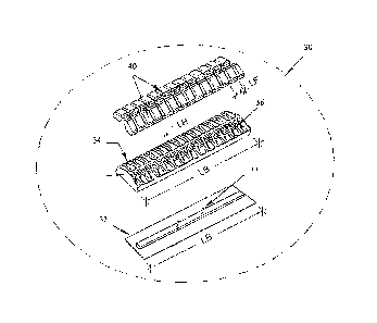
Fig. 7 is a view of the protective liner assembly according to the present
invention;
Fig. 8 is a plan view of a preferred form of wear element of the liner
assembly of the
present invention;
Fig. 9 is a plan view of another preferred form of wear element of the liner
assembly of the
present invention; and
Figs. 10, 11, 12, 13, 14, 15 and 16 are different configurations of the wear
element and the
surface exposed to the impact of the apparatus according to the present
invention.
A partial view of a typical grinding mill is shown in Fig. 1 having
conventional liner
assemblies has been described earlier with reference to Figs. 2 to 4.

CA 02595002 2007-07-16
WO 2006/076764 PCT/AU2006/000049
-5-
Fig. 5 is a partial schematic illustration of a grinding mill with liner
assemblies according
to the present invention. The mill has a shell 10 with a plurality of lifter
bars 12 mounted
to the inner surface of the shell 10. The lifter bars 12 are circumferentially
spaced apart
around the inner surface of the shell 10 and extend in the direction of the
axis of rotation of
the shell. The spaces between adjacent lifter bars 12 form channels 14 of
width J. The
length of the bars 12 is shown as LM which is the inner length of the shell in
the direction
of rotation thereof. Preferably the number of channels 14 is the same as the
number of
lifter bars 12.
Each channel 14 is adapted to have mounted therein a liner assembly 30 in
accordance
with the present invention. The liner assembly 30 includes a base member 32
which is
adapted to be mounted to the inner surface of the shell by suitable fastenings
such as bolts
(not shown). The base member 32 includes an elongated plate having mounting
elements
33 thereon.
The liner assembly further includes an elastomeric cushioning member 34 which
is secured
to the base member 32. The cushioning member 34 has a plurality of cavities 36
therein
for receiving wear elements 40. The width of the liner assembly is about the
same as the
width of the channels 14 between adjacent lifter bars 12 and the length of the
liner
assembly is between 2 and 12 times the width of the member.
The liner assembly has a base wall having an underside which substantially
confonns to
the curvature of the inner surface of the shell and side walls extending from
the base wall
and being of a height K which is approximately the same as the height of the
side walls of
the lifter bars 14.
As shown in Fig. 8, the wear elements are arranged in two rows 44 and 45 in
which the
elements are offset from one another. In Fig. 9 three rows 44, 45 and 46 are
shown with
the elements in adjacent rows being offset from one another.
The wear elements may be formed from metal, a metal alloy, ceramic or any
other suitable

CA 02595002 2007-07-16
WO 2006/076764 PCT/AU2006/000049
-6-
material. The wear elements preferably have a Brinell hardness between 350 and
800
BHN. The cushioning member may be a natural or synthetic material or a
combination of
both with a Shore hardness between 30 to 85 hardness Shore A.
Figs. 10 to 16 illustrate in cross section various configurations and shapes
of the
cushioning member and wear elements. Figs. 10, 13, 14, 15 and 16 show a single
row of
wear elements 40 of different cross sectional shapes. Fig. 11 illustrates an
arrangement
with two rows of wear elements 40 and Fig. 12 three rows of wear elements.
Finally, it is to be understood that the inventive concept in any of its
aspects can be
incorporated in many different constructions so that the generality of the
preceding
description is not to be superseded by the particularity of the attached
drawings. Various
alterations, modifications and/or additions may be incorporated into the
various
constructions and arrangements of parts without departing from the spirit or
asnbit of the
invention.

Dessin représentatif
Une figure unique qui représente un dessin illustrant l'invention.
États administratifs

2024-08-01 : Dans le cadre de la transition vers les Brevets de nouvelle génération (BNG), la base de données sur les brevets canadiens (BDBC) contient désormais un Historique d'événement plus détaillé, qui reproduit le Journal des événements de notre nouvelle solution interne.

Veuillez noter que les événements débutant par « Inactive : » se réfèrent à des événements qui ne sont plus utilisés dans notre nouvelle solution interne.

Pour une meilleure compréhension de l'état de la demande ou brevet qui figure sur cette page, la rubrique Mise en garde , et les descriptions de Brevet , Historique d'événement , Taxes périodiques et Historique des paiements devraient être consultées.

Historique d'événement

Description Date
Lettre envoyée 2024-01-16
Représentant commun nommé 2019-10-30
Requête visant le maintien en état reçue 2015-01-06
Accordé par délivrance 2014-12-30
Inactive : Page couverture publiée 2014-12-29
Inactive : Taxe finale reçue 2014-10-14
Préoctroi 2014-10-14
Demande de correction du demandeur reçue 2014-10-10
Un avis d'acceptation est envoyé 2014-04-14
Lettre envoyée 2014-04-14
Un avis d'acceptation est envoyé 2014-04-14
Requête visant le maintien en état reçue 2014-01-06
Inactive : Lettre officielle 2013-02-01
Inactive : Approuvée aux fins d'acceptation (AFA) 2013-01-30
Requête visant le maintien en état reçue 2013-01-04
Demande de correction du demandeur reçue 2012-09-04
Modification reçue - modification volontaire 2012-08-31
Inactive : Dem. de l'examinateur par.30(2) Règles 2012-03-01
Demande de correction du demandeur reçue 2011-09-12
Lettre envoyée 2010-11-10
Requête d'examen reçue 2010-11-01
Exigences pour une requête d'examen - jugée conforme 2010-11-01
Toutes les exigences pour l'examen - jugée conforme 2010-11-01
Lettre envoyée 2007-12-04
Inactive : Déclaration des droits - Formalités 2007-10-15
Inactive : Transfert individuel 2007-10-15
Inactive : Notice - Entrée phase nat. - Pas de RE 2007-10-10
Inactive : Page couverture publiée 2007-10-03
Inactive : Notice - Entrée phase nat. - Pas de RE 2007-10-01
Inactive : CIB en 1re position 2007-08-24
Demande reçue - PCT 2007-08-23
Exigences pour l'entrée dans la phase nationale - jugée conforme 2007-07-16
Demande publiée (accessible au public) 2006-07-27

Historique d'abandonnement

Il n'y a pas d'historique d'abandonnement

Taxes périodiques

Le dernier paiement a été reçu le 2014-01-06

Avis : Si le paiement en totalité n'a pas été reçu au plus tard à la date indiquée, une taxe supplémentaire peut être imposée, soit une des taxes suivantes :

  • taxe de rétablissement ;
  • taxe pour paiement en souffrance ; ou
  • taxe additionnelle pour le renversement d'une péremption réputée.

Les taxes sur les brevets sont ajustées au 1er janvier de chaque année. Les montants ci-dessus sont les montants actuels s'ils sont reçus au plus tard le 31 décembre de l'année en cours.
Veuillez vous référer à la page web des taxes sur les brevets de l'OPIC pour voir tous les montants actuels des taxes.

Titulaires au dossier

Les titulaires actuels et antérieures au dossier sont affichés en ordre alphabétique.

Titulaires actuels au dossier
VULCO S.A.
Titulaires antérieures au dossier
RICARDO ABARCA MELO
RICARDO FERNANDEZ DABERTI
Les propriétaires antérieurs qui ne figurent pas dans la liste des « Propriétaires au dossier » apparaîtront dans d'autres documents au dossier.
Documents

Pour visionner les fichiers sélectionnés, entrer le code reCAPTCHA :


Pour visualiser une image, cliquer sur un lien dans la colonne description du document. Pour télécharger l'image (les images), cliquer l'une ou plusieurs cases à cocher dans la première colonne et ensuite cliquer sur le bouton "Télécharger sélection en format PDF (archive Zip)" ou le bouton "Télécharger sélection (en un fichier PDF fusionné)".

Liste des documents de brevet publiés et non publiés sur la BDBC .

Si vous avez des difficultés à accéder au contenu, veuillez communiquer avec le Centre de services à la clientèle au 1-866-997-1936, ou envoyer un courriel au Centre de service à la clientèle de l'OPIC.


Description du
Document 
Date
(aaaa-mm-jj) 
Nombre de pages   Taille de l'image (Ko) 
Dessin représentatif 2014-12-07 1 14
Description 2007-07-15 6 252
Revendications 2007-07-15 2 84
Dessins 2007-07-15 5 134
Abrégé 2007-07-15 1 9
Dessin représentatif 2007-10-01 1 18
Revendications 2012-08-30 4 234
Abrégé 2014-04-13 1 9
Avis d'entree dans la phase nationale 2007-10-09 1 207
Courtoisie - Certificat d'enregistrement (document(s) connexe(s)) 2007-12-03 1 105
Rappel - requête d'examen 2010-09-19 1 118
Accusé de réception de la requête d'examen 2010-11-09 1 189
Avis du commissaire - Demande jugée acceptable 2014-04-13 1 161
Avis du commissaire - Non-paiement de la taxe pour le maintien en état des droits conférés par un brevet 2024-02-26 1 542
PCT 2007-07-15 18 773
Correspondance 2007-09-30 1 23
Correspondance 2007-10-14 1 34
Taxes 2008-12-22 1 55
Taxes 2009-12-20 1 49
Taxes 2010-12-20 1 44
Correspondance 2011-09-11 1 32
Taxes 2012-01-02 1 45
Correspondance 2012-09-03 6 203
Taxes 2013-01-03 1 45
Correspondance 2013-01-31 1 15
Taxes 2014-01-05 1 46
Correspondance 2014-10-09 6 213
Correspondance 2014-10-13 2 43
Taxes 2015-01-05 1 55