Language selection

Search

Patent 2595054 Summary

Third-party information liability

Some of the information on this Web page has been provided by external sources. The Government of Canada is not responsible for the accuracy, reliability or currency of the information supplied by external sources. Users wishing to rely upon this information should consult directly with the source of the information. Content provided by external sources is not subject to official languages, privacy and accessibility requirements.

Claims and Abstract availability

Any discrepancies in the text and image of the Claims and Abstract are due to differing posting times. Text of the Claims and Abstract are posted:

  • At the time the application is open to public inspection;
  • At the time of issue of the patent (grant).
(12) Patent Application: (11) CA 2595054
(54) English Title: ADJUSTABLE HEADREST ASSEMBLY
(54) French Title: APPUIE-TETE REGLABLE
Status: Deemed Abandoned and Beyond the Period of Reinstatement - Pending Response to Notice of Disregarded Communication
Bibliographic Data
(51) International Patent Classification (IPC):
  • A47C 07/38 (2006.01)
(72) Inventors :
  • VIGER, DENIS (Canada)
(73) Owners :
  • LES ACIERS ROBOND INC.
(71) Applicants :
  • LES ACIERS ROBOND INC. (Canada)
(74) Agent:
(74) Associate agent:
(45) Issued:
(22) Filed Date: 2007-06-21
(41) Open to Public Inspection: 2008-01-06
Availability of licence: N/A
Dedicated to the Public: N/A
(25) Language of filing: English

Patent Cooperation Treaty (PCT): No

(30) Application Priority Data:
Application No. Country/Territory Date
60/818,548 (United States of America) 2006-07-06

Abstracts

English Abstract


A headrest assembly for a chair or sofa includes a fixed rear section, and a
front section adapted to slide upwardly and forwardly to an inclined
orientation with
respect to the rear section. Movement of the front section is controlled by a
linear
actuator, which is connected via a switch to a source of power such as a
battery.


Claims

Note: Claims are shown in the official language in which they were submitted.

CLAIMS:
1. A headrest assembly comprising a rear section for mounting in a fixed
position on a chair or sofa; a front section pivotally and slidably mounted on
said
front section for movement between various inclined positions with respect to
said
rear section; and an actuator for moving said front section with respect to
said rear
section between the various inclined positions.
2. The headrest assembly of claim 1, wherein said rear section includes a
back plate for mounting on the chair or sofa, and a pair of rear end plates
extending
forwardly from said back plate; and said front plate includes a front wall and
a pair of
front end walls extending rearwardly from said front wall into overlapping
relationship
with said rear end plates.
3. The headrest assembly of claim 2, wherein said rear and front sections
are generally C-shaped when viewed from above or below.
4. The headrest assembly of claim 2, wherein said rear end plates have
an inverted L-shaped configuration.
5. The headrest assembly of claim 4 including a vertical slot in a vertical
arm of each said rear end plate, an inclined slot in an upper, forwardly
inclined arm
of each said rear end plate; and a pair of pins extending inwardly from each
said end
wall of the front section through said slots, whereby the front section can
slide
vertically while tilting outwardly with respect to said rear section of the
assembly.
6. The headrest assembly of claim 5, wherein said linear actuator
includes a housing having first and second ends, the first end being pivotally
connected to a bottom end of said back plate of the rear section; and a
reciprocating
shaft extending out of the second end of the housing, the shaft having a free
end

pivotally connected to a top end of said front wall of the front section,
movement of
said shaft in said housing causing tilting of the front section with respect
to said rear
section.
7. The headrest assembly of claim 6, wherein the linear actuator extends
between the bottom center of the rear plate and the top center of the front
wall.
6

Description

Note: Descriptions are shown in the official language in which they were submitted.


CA 02595054 2007-06-21
ADJUSTABLE HEADREST ASSEMBLY
BACKGROUND OF THE INVENTION
Field of the Invention
This invention relates to an adjustable headrest assembly.
While the headrest assembly was designed primarily for use on a chair or
sofa, it will be appreciated that the assembly can be used in an automotive or
other
vehicle.
Description of Related Art
There is a considerable volume of patent literature relating to adjustable
headrests. In this connection, reference is made to US Patents Nos. 4,370,898,
which issued to K. Maruyama on February 1, 1983, 4,640,549, which issued to M.
Yokota on February 3, 1987, 4,668,014, which issued to B. Boisset on May 26,
1987, 4,674,797, which issued to T. Tateyama on June 23, 1987, 5,236,246,
which
issued to D.J. Harrell on August 17, 1993, 5,238,295, which issued to D.J.
Harrell on
August 24, 1993, 5,346,283, which issued to U. Steininger et al on September
13,
1994 and 6,471,296, which issued to M.A. Lance on October 29, 2002.
It will be noted that most of the apparatuses disclosed by the above listed
patents are somewhat complicated and consequently expensive to manufacture.
BRIEF SUMMARY OF THE INVENTION
The present invention provides a relatively simple headrest assembly which
includes a few, easily assembled elements.
Accordingly, the invention relates to a headrest assembly comprising a rear
section for mounting in a fixed position on a chair or sofa; a front section
pivotally
and slidably mounted on said front section for movement between various
inclined
1

CA 02595054 2007-06-21
positions with respect to said rear section; and an actuator for moving said
front
section with respect to said rear section between the various inclined
positions.
BRIEF DESCRIPTION OF THE DRAWINGS
The invention is described below with reference to the accompanying
drawings, wherein:
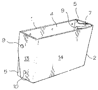
Figure 1 is a isometric view of a headrest assembly in accordance with the
present invention in a first position;
Figure 2 is an isometric view of the headrest assembly of Fig. 1 in a second
position;
Figure 3 is an isometric view of a rear section of the headrest assembly of
Figs. 1 and 2; and
Figure 4 is a cross-sectional view of the headrest assembly of Figs. 1 to 3.
DETAILED DESCRIPTION OF THE INVENTION
With reference to the drawings, the principal elements of the headrest
assembly of the present invention include a rear section 1, a front section 2
and a
linear actuator 3. The rear section 1 of the assembly includes a rectangular
back
plate 4 for mounting in a fixed position on a chair or sofa back (not shown).
The rear
section can be mounted on the rear of a padded headrest (not shown). It will
be
appreciated that the plate 4 could also define the back of a headrest. A pair
of
generally inverted L-shaped end plates 5 are integral with the back plate 4
and
extend forwardly therefrom. Each end plate 5 includes upper and lower slots 7
and
8, respectively for slidably receiving pins 9 and 10, respectively. The upper
slots 7
are inclined upwardly and outwardly, and the lower slots 8 are vertical. The
pins 9
and 10 extend inwardly from the end walls 13 of the front section 2 of the
headrest
2

CA 02595054 2007-06-21
assembly. The end walls 13 are integral with a rectangular front wall 14.
Thus, the
front section 2 of the assembly is generally C-shaped when viewed from above
or
below, and the end walls 13 overlap the end plates 5 of the rear section 1.
While
they are not shown, it will be appreciated that padding and a cover would be
added
to the whole assembly or at least to the end walls 13 and the front wall 14 of
the
front section. Accordion pleats in the cover would permit movement of the
front
section relative to the rear section.
The linear actuator 3, which is a piece of off-the-shelf hardware, includes a
direct current electric motor 16 connected through switches to a source of
electrical
power such as a battery (not shown). The switches can be mounted for manual
operation in or on the arm of a chair or sofa. The motor 16 is connected to a
spindle
(not shown) in the housing 17 by a transmission 18. A coupling 20 on the
bottom,
transmission end of the housing is pivotally connected to the center of the
bottom
end of the rear section back plate 4 by a clevis 21. A reciprocating shaft 22
extending out of the top end of the housing 17 is pivotally connected to the
center of
the top end of the front wall 14 of the second section 2 by a clevis 23. A
suitable
linear actuator is available from Jaeger Industrial Co. Ltd., Taipei, Taiwan,
R.O.C.
In operation, with the shaft 22 of the linear actuator 3 retracted (Fig. 3),
the
bottom waII14 of the front section 2 defines a small acute angle with the back
plate 4
of the rear section 1 (Fig. 1). When the shaft 22 of the linear actuator is
extended,
the pins 9 slide upwardly and outwardly in the slots 7 and the pins 10 side
upwardly
in slots 8 so that the front wall 14 defines a larger acute angle with respect
to the
plate 4, i.e. the front section 2 becomes more inclined with respect to the
rear
section 1. Thus, by connecting the linear actuator 3 to a forward and reverse
switch
3

CA 02595054 2007-06-21
(not shown), which is in turn connected to a source of electrical power, the
inclination or tilt of the front section of the headrest assembly can be
changed.
4

Representative Drawing
A single figure which represents the drawing illustrating the invention.
Administrative Status

2024-08-01:As part of the Next Generation Patents (NGP) transition, the Canadian Patents Database (CPD) now contains a more detailed Event History, which replicates the Event Log of our new back-office solution.

Please note that "Inactive:" events refers to events no longer in use in our new back-office solution.

For a clearer understanding of the status of the application/patent presented on this page, the site Disclaimer , as well as the definitions for Patent , Event History , Maintenance Fee  and Payment History  should be consulted.

Event History

Description Date
Inactive: Office letter 2020-11-09
Revocation of Agent Requirements Determined Compliant 2020-09-01
Inactive: IPC expired 2018-01-01
Application Not Reinstated by Deadline 2011-06-21
Time Limit for Reversal Expired 2011-06-21
Deemed Abandoned - Failure to Respond to Maintenance Fee Notice 2010-06-21
Inactive: IPC assigned 2008-08-12
Application Published (Open to Public Inspection) 2008-01-06
Inactive: Cover page published 2008-01-06
Inactive: IPC assigned 2007-11-26
Inactive: First IPC assigned 2007-11-26
Inactive: Declaration of entitlement - Formalities 2007-08-27
Small Entity Declaration Determined Compliant 2007-08-27
Inactive: Declaration of entitlement/transfer requested - Formalities 2007-08-23
Inactive: Filing certificate - No RFE (English) 2007-08-23
Extension of Time to Top-up Small Entity Fees Requirements Determined Compliant 2007-08-23
Application Received - Regular National 2007-08-23
Small Entity Declaration Determined Compliant 2007-06-21

Abandonment History

Abandonment Date Reason Reinstatement Date
2010-06-21

Maintenance Fee

The last payment was received on 2009-06-04

Note : If the full payment has not been received on or before the date indicated, a further fee may be required which may be one of the following

  • the reinstatement fee;
  • the late payment fee; or
  • additional fee to reverse deemed expiry.

Patent fees are adjusted on the 1st of January every year. The amounts above are the current amounts if received by December 31 of the current year.
Please refer to the CIPO Patent Fees web page to see all current fee amounts.

Fee History

Fee Type Anniversary Year Due Date Paid Date
Application fee - standard 2007-06-21
MF (application, 2nd anniv.) - small 02 2009-06-22 2009-06-04
Owners on Record

Note: Records showing the ownership history in alphabetical order.

Current Owners on Record
LES ACIERS ROBOND INC.
Past Owners on Record
DENIS VIGER
Past Owners that do not appear in the "Owners on Record" listing will appear in other documentation within the application.
Documents

To view selected files, please enter reCAPTCHA code :


To view images, click a link in the Document Description column. To download the documents, select one or more checkboxes in the first column and then click the "Download Selected in PDF format (Zip Archive)" or the "Download Selected as Single PDF" button.

List of published and non-published patent-specific documents on the CPD .

If you have any difficulty accessing content, you can call the Client Service Centre at 1-866-997-1936 or send them an e-mail at CIPO Client Service Centre.


Document
Description 
Date
(yyyy-mm-dd) 
Number of pages   Size of Image (KB) 
Abstract 2007-06-20 1 9
Description 2007-06-20 4 121
Claims 2007-06-20 2 49
Drawings 2007-06-20 2 41
Representative drawing 2007-12-10 1 8
Filing Certificate (English) 2007-08-22 1 158
Reminder of maintenance fee due 2009-02-23 1 111
Courtesy - Abandonment Letter (Maintenance Fee) 2010-08-15 1 174
Correspondence 2007-08-26 3 65
Fees 2009-06-03 1 24