Sélection de la langue

Search

Sommaire du brevet 2595054 

Énoncé de désistement de responsabilité concernant l'information provenant de tiers

Une partie des informations de ce site Web a été fournie par des sources externes. Le gouvernement du Canada n'assume aucune responsabilité concernant la précision, l'actualité ou la fiabilité des informations fournies par les sources externes. Les utilisateurs qui désirent employer cette information devraient consulter directement la source des informations. Le contenu fourni par les sources externes n'est pas assujetti aux exigences sur les langues officielles, la protection des renseignements personnels et l'accessibilité.

Disponibilité de l'Abrégé et des Revendications

L'apparition de différences dans le texte et l'image des Revendications et de l'Abrégé dépend du moment auquel le document est publié. Les textes des Revendications et de l'Abrégé sont affichés :

  • lorsque la demande peut être examinée par le public;
  • lorsque le brevet est émis (délivrance).
(12) Demande de brevet: (11) CA 2595054
(54) Titre français: APPUIE-TETE REGLABLE
(54) Titre anglais: ADJUSTABLE HEADREST ASSEMBLY
Statut: Réputée abandonnée et au-delà du délai pour le rétablissement - en attente de la réponse à l’avis de communication rejetée
Données bibliographiques
(51) Classification internationale des brevets (CIB):
  • A47C 07/38 (2006.01)
(72) Inventeurs :
  • VIGER, DENIS (Canada)
(73) Titulaires :
  • LES ACIERS ROBOND INC.
(71) Demandeurs :
  • LES ACIERS ROBOND INC. (Canada)
(74) Agent:
(74) Co-agent:
(45) Délivré:
(22) Date de dépôt: 2007-06-21
(41) Mise à la disponibilité du public: 2008-01-06
Licence disponible: S.O.
Cédé au domaine public: S.O.
(25) Langue des documents déposés: Anglais

Traité de coopération en matière de brevets (PCT): Non

(30) Données de priorité de la demande:
Numéro de la demande Pays / territoire Date
60/818,548 (Etats-Unis d'Amérique) 2006-07-06

Abrégés

Abrégé anglais


A headrest assembly for a chair or sofa includes a fixed rear section, and a
front section adapted to slide upwardly and forwardly to an inclined
orientation with
respect to the rear section. Movement of the front section is controlled by a
linear
actuator, which is connected via a switch to a source of power such as a
battery.

Revendications

Note : Les revendications sont présentées dans la langue officielle dans laquelle elles ont été soumises.


CLAIMS:
1. A headrest assembly comprising a rear section for mounting in a fixed
position on a chair or sofa; a front section pivotally and slidably mounted on
said
front section for movement between various inclined positions with respect to
said
rear section; and an actuator for moving said front section with respect to
said rear
section between the various inclined positions.
2. The headrest assembly of claim 1, wherein said rear section includes a
back plate for mounting on the chair or sofa, and a pair of rear end plates
extending
forwardly from said back plate; and said front plate includes a front wall and
a pair of
front end walls extending rearwardly from said front wall into overlapping
relationship
with said rear end plates.
3. The headrest assembly of claim 2, wherein said rear and front sections
are generally C-shaped when viewed from above or below.
4. The headrest assembly of claim 2, wherein said rear end plates have
an inverted L-shaped configuration.
5. The headrest assembly of claim 4 including a vertical slot in a vertical
arm of each said rear end plate, an inclined slot in an upper, forwardly
inclined arm
of each said rear end plate; and a pair of pins extending inwardly from each
said end
wall of the front section through said slots, whereby the front section can
slide
vertically while tilting outwardly with respect to said rear section of the
assembly.
6. The headrest assembly of claim 5, wherein said linear actuator
includes a housing having first and second ends, the first end being pivotally
connected to a bottom end of said back plate of the rear section; and a
reciprocating
shaft extending out of the second end of the housing, the shaft having a free
end

pivotally connected to a top end of said front wall of the front section,
movement of
said shaft in said housing causing tilting of the front section with respect
to said rear
section.
7. The headrest assembly of claim 6, wherein the linear actuator extends
between the bottom center of the rear plate and the top center of the front
wall.
6

Description

Note : Les descriptions sont présentées dans la langue officielle dans laquelle elles ont été soumises.

CA 02595054 2007-06-21
ADJUSTABLE HEADREST ASSEMBLY
BACKGROUND OF THE INVENTION
Field of the Invention
This invention relates to an adjustable headrest assembly.
While the headrest assembly was designed primarily for use on a chair or
sofa, it will be appreciated that the assembly can be used in an automotive or
other
vehicle.
Description of Related Art
There is a considerable volume of patent literature relating to adjustable
headrests. In this connection, reference is made to US Patents Nos. 4,370,898,
which issued to K. Maruyama on February 1, 1983, 4,640,549, which issued to M.
Yokota on February 3, 1987, 4,668,014, which issued to B. Boisset on May 26,
1987, 4,674,797, which issued to T. Tateyama on June 23, 1987, 5,236,246,
which
issued to D.J. Harrell on August 17, 1993, 5,238,295, which issued to D.J.
Harrell on
August 24, 1993, 5,346,283, which issued to U. Steininger et al on September
13,
1994 and 6,471,296, which issued to M.A. Lance on October 29, 2002.
It will be noted that most of the apparatuses disclosed by the above listed
patents are somewhat complicated and consequently expensive to manufacture.
BRIEF SUMMARY OF THE INVENTION
The present invention provides a relatively simple headrest assembly which
includes a few, easily assembled elements.
Accordingly, the invention relates to a headrest assembly comprising a rear
section for mounting in a fixed position on a chair or sofa; a front section
pivotally
and slidably mounted on said front section for movement between various
inclined
1

CA 02595054 2007-06-21
positions with respect to said rear section; and an actuator for moving said
front
section with respect to said rear section between the various inclined
positions.
BRIEF DESCRIPTION OF THE DRAWINGS
The invention is described below with reference to the accompanying
drawings, wherein:
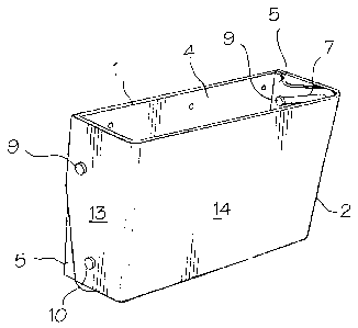
Figure 1 is a isometric view of a headrest assembly in accordance with the
present invention in a first position;
Figure 2 is an isometric view of the headrest assembly of Fig. 1 in a second
position;
Figure 3 is an isometric view of a rear section of the headrest assembly of
Figs. 1 and 2; and
Figure 4 is a cross-sectional view of the headrest assembly of Figs. 1 to 3.
DETAILED DESCRIPTION OF THE INVENTION
With reference to the drawings, the principal elements of the headrest
assembly of the present invention include a rear section 1, a front section 2
and a
linear actuator 3. The rear section 1 of the assembly includes a rectangular
back
plate 4 for mounting in a fixed position on a chair or sofa back (not shown).
The rear
section can be mounted on the rear of a padded headrest (not shown). It will
be
appreciated that the plate 4 could also define the back of a headrest. A pair
of
generally inverted L-shaped end plates 5 are integral with the back plate 4
and
extend forwardly therefrom. Each end plate 5 includes upper and lower slots 7
and
8, respectively for slidably receiving pins 9 and 10, respectively. The upper
slots 7
are inclined upwardly and outwardly, and the lower slots 8 are vertical. The
pins 9
and 10 extend inwardly from the end walls 13 of the front section 2 of the
headrest
2

CA 02595054 2007-06-21
assembly. The end walls 13 are integral with a rectangular front wall 14.
Thus, the
front section 2 of the assembly is generally C-shaped when viewed from above
or
below, and the end walls 13 overlap the end plates 5 of the rear section 1.
While
they are not shown, it will be appreciated that padding and a cover would be
added
to the whole assembly or at least to the end walls 13 and the front wall 14 of
the
front section. Accordion pleats in the cover would permit movement of the
front
section relative to the rear section.
The linear actuator 3, which is a piece of off-the-shelf hardware, includes a
direct current electric motor 16 connected through switches to a source of
electrical
power such as a battery (not shown). The switches can be mounted for manual
operation in or on the arm of a chair or sofa. The motor 16 is connected to a
spindle
(not shown) in the housing 17 by a transmission 18. A coupling 20 on the
bottom,
transmission end of the housing is pivotally connected to the center of the
bottom
end of the rear section back plate 4 by a clevis 21. A reciprocating shaft 22
extending out of the top end of the housing 17 is pivotally connected to the
center of
the top end of the front wall 14 of the second section 2 by a clevis 23. A
suitable
linear actuator is available from Jaeger Industrial Co. Ltd., Taipei, Taiwan,
R.O.C.
In operation, with the shaft 22 of the linear actuator 3 retracted (Fig. 3),
the
bottom waII14 of the front section 2 defines a small acute angle with the back
plate 4
of the rear section 1 (Fig. 1). When the shaft 22 of the linear actuator is
extended,
the pins 9 slide upwardly and outwardly in the slots 7 and the pins 10 side
upwardly
in slots 8 so that the front wall 14 defines a larger acute angle with respect
to the
plate 4, i.e. the front section 2 becomes more inclined with respect to the
rear
section 1. Thus, by connecting the linear actuator 3 to a forward and reverse
switch
3

CA 02595054 2007-06-21
(not shown), which is in turn connected to a source of electrical power, the
inclination or tilt of the front section of the headrest assembly can be
changed.
4

Dessin représentatif
Une figure unique qui représente un dessin illustrant l'invention.
États administratifs

2024-08-01 : Dans le cadre de la transition vers les Brevets de nouvelle génération (BNG), la base de données sur les brevets canadiens (BDBC) contient désormais un Historique d'événement plus détaillé, qui reproduit le Journal des événements de notre nouvelle solution interne.

Veuillez noter que les événements débutant par « Inactive : » se réfèrent à des événements qui ne sont plus utilisés dans notre nouvelle solution interne.

Pour une meilleure compréhension de l'état de la demande ou brevet qui figure sur cette page, la rubrique Mise en garde , et les descriptions de Brevet , Historique d'événement , Taxes périodiques et Historique des paiements devraient être consultées.

Historique d'événement

Description Date
Inactive : Lettre officielle 2020-11-09
Exigences relatives à la révocation de la nomination d'un agent - jugée conforme 2020-09-01
Inactive : CIB expirée 2018-01-01
Demande non rétablie avant l'échéance 2011-06-21
Le délai pour l'annulation est expiré 2011-06-21
Réputée abandonnée - omission de répondre à un avis sur les taxes pour le maintien en état 2010-06-21
Inactive : CIB attribuée 2008-08-12
Demande publiée (accessible au public) 2008-01-06
Inactive : Page couverture publiée 2008-01-06
Inactive : CIB attribuée 2007-11-26
Inactive : CIB en 1re position 2007-11-26
Inactive : Déclaration des droits - Formalités 2007-08-27
Déclaration du statut de petite entité jugée conforme 2007-08-27
Inactive : Décl. droits/transfert dem. - Formalités 2007-08-23
Inactive : Certificat de dépôt - Sans RE (Anglais) 2007-08-23
Exigences de prorogation de délai pour compléter le paiement de la taxe applicable aux petites entités - jugée conforme 2007-08-23
Demande reçue - nationale ordinaire 2007-08-23
Déclaration du statut de petite entité jugée conforme 2007-06-21

Historique d'abandonnement

Date d'abandonnement Raison Date de rétablissement
2010-06-21

Taxes périodiques

Le dernier paiement a été reçu le 2009-06-04

Avis : Si le paiement en totalité n'a pas été reçu au plus tard à la date indiquée, une taxe supplémentaire peut être imposée, soit une des taxes suivantes :

  • taxe de rétablissement ;
  • taxe pour paiement en souffrance ; ou
  • taxe additionnelle pour le renversement d'une péremption réputée.

Les taxes sur les brevets sont ajustées au 1er janvier de chaque année. Les montants ci-dessus sont les montants actuels s'ils sont reçus au plus tard le 31 décembre de l'année en cours.
Veuillez vous référer à la page web des taxes sur les brevets de l'OPIC pour voir tous les montants actuels des taxes.

Historique des taxes

Type de taxes Anniversaire Échéance Date payée
Taxe pour le dépôt - générale 2007-06-21
TM (demande, 2e anniv.) - petite 02 2009-06-22 2009-06-04
Titulaires au dossier

Les titulaires actuels et antérieures au dossier sont affichés en ordre alphabétique.

Titulaires actuels au dossier
LES ACIERS ROBOND INC.
Titulaires antérieures au dossier
DENIS VIGER
Les propriétaires antérieurs qui ne figurent pas dans la liste des « Propriétaires au dossier » apparaîtront dans d'autres documents au dossier.
Documents

Pour visionner les fichiers sélectionnés, entrer le code reCAPTCHA :


Pour visualiser une image, cliquer sur un lien dans la colonne description du document. Pour télécharger l'image (les images), cliquer l'une ou plusieurs cases à cocher dans la première colonne et ensuite cliquer sur le bouton "Télécharger sélection en format PDF (archive Zip)" ou le bouton "Télécharger sélection (en un fichier PDF fusionné)".

Liste des documents de brevet publiés et non publiés sur la BDBC .

Si vous avez des difficultés à accéder au contenu, veuillez communiquer avec le Centre de services à la clientèle au 1-866-997-1936, ou envoyer un courriel au Centre de service à la clientèle de l'OPIC.


Description du
Document 
Date
(aaaa-mm-jj) 
Nombre de pages   Taille de l'image (Ko) 
Abrégé 2007-06-20 1 9
Description 2007-06-20 4 121
Revendications 2007-06-20 2 49
Dessins 2007-06-20 2 41
Dessin représentatif 2007-12-10 1 8
Certificat de dépôt (anglais) 2007-08-22 1 158
Rappel de taxe de maintien due 2009-02-23 1 111
Courtoisie - Lettre d'abandon (taxe de maintien en état) 2010-08-15 1 174
Correspondance 2007-08-26 3 65
Taxes 2009-06-03 1 24