Note: Descriptions are shown in the official language in which they were submitted.
CA 02595078 2007-07-17
DESCRIPTION
REINFORCING BAR TYING TOOL
Technical Field
The present invention relates a reinforcing bar tying tool.
Background Art
An electric reinforcing bar tying tool is widely used as means
for saving labor and for improving efficiency in a reinforcing bar
tying work. For example, Japanese Patent No. 3496463 discloses an
electric reinforcing bar tying tool including a tie wire feeding
mechanism which feeds a tie wire wound around a reel so as to wind
it around reinforcing bars, a tie wire cutting mechanism which cuts
a rear end of a tie wire loop wound around the reinforcing bars
so as to separate it from the succeeding tie wire, and a tie wire
twisting mechanism which twists the tie wire loop to tie the
reinforcing bars, in which, when a trigger lever is pulled, one
cycle operation from the feeding of the tie wire to the twisting
of the tie wire and the tying of the reinforcing bars can be executed
in quite a short time.
Further, such as JP-A-2003-267307, JP-A-2004-142813,
JP-A-2004-142814 disclose an electric reinforcing bar tying tool
in which, after a tie wire is fed to form a tie wire loop surrounding
reinforcing bars, a tie wire twisting mechanism clamps a tip end
1
CA 02595078 2007-07-17
portion of the tie wire and the tie wire feeding mechanism is driven
reversely to pull back the tie wire to wind the tie wire around
the reinforcing bars, and then the tie wire twisting mechanism twists
the tie wire loop to tie the reinforcing bars, whereby a length
of the tie wire loop is adjusted in accordance with the thickness
of the reinforcing bar so that a required amount of the tie wire
is reduced and a binding finish is improved.
An explanation will be made below as to a problem of such
a reinforcing bar tying tool in which, after a tie wire is fed to
forma tie wire loop surrounding reinforcing bars, a tie wire twisting
mechanism clamps a tip end portion of the tie wire and the tie wire
feeding mechanism is driven reversely to pull back the tie wire
to wind the tie wire around the reinforcing bars, and then the tie
wire twistingmechanism twists the tiewire loop to tie the reinforcing
bars.
When reversely driving the tie wire feeding mechanism to pull
back the tie wire and to wind the tie wire around the reinforcing
bars the tie wire twisting mechanism needs to clamp the tip end
portion of the tie wire. However, there is a case where the tie
wire is not placed between clamps of the tie wire twisting mechanism
for some reasons such as an excessive curvature of the tie wire
or an abnormality of the feeding, so that the tie wire cannot be
clamped. If the tie wire is not clamped, the entire tie wire loop
is pulled back at the time when the tie wire feeding mechanism is
reversely driven, so that a tip end of the tie wire may move backward
2
CA 02595078 2007-07-17
than a feeding start position (a cutting position of a cutter of
the tie wire cutting mechanism).
Because a feeding amount of the tie wire is controlled to
be constant in a reinforcing bar tying tool, when the tip end of
the tie wire is moved backward than a regular position, a feeding
length of the tie wire becomes insufficient in a subsequent tying
cycle, whereby a tying operation cannot be performed like the
preceding tying cycle which has been failed. Thus, in such a case,
the tying operation is interrupted and troublesome works are required
such as manually feeding the tip end of the tie wire to the regular
position and setting the tie wire again.
Disclosure of the invention
One or more embodiments of the present invention provide a
reinforcing bar tying tool which can execute a subsequent tying
cycle properly even in a case where a tying operation is failed
due to a failure in a tie wire feeing operation, whereby a troublesome
work such as a resetting operation of a tie wire is eliminated.
According to one or more embodiments of the invention, a
reinforcing bar tying tool includes a tie wire feeding mechanism
which feeds a tie wire wound around a reel toward a tie wire guide
nose so as to form a tie wire loop around reinforcing bars, a tie
wire cutting mechanism which cuts a rear end portion of the tie
wire loop to separate the tie wire loop from a succeeding tie wire,
and a tie wire twisting mechanism which clamps and twists the tie
3
CA 02595078 2007-07-17
wire loop, wherein, after forming the tie wire loop, the reinforcing
bar tying tool performs steps of clamping a tip end portion of the
tie wire loop, driving the tie wire feeding mechanism reversely
to pull back the tie wire, cutting the rear end portion of the tie
wire loop while the tie wire loop is in close contact with the
reinforcing bars, and clamping and twisting both end portions of
the tie wire loop, wherein the reinforcing bar tying tool further
includes a driving load detecting device which detects a driving
load amount of the tie wire cutting mechanism, and a tie wire feeding
amount control device which controls a tie wire feeding amount in
a subsequent tying operation in accordance with the driving load
amount detected by the driving load detecting device, wherein, when
the driving load amount is equal to or less than a cutting
determination reference value in the step of cutting the tie wire,
the tie wire feeding amount is compensated by feeding the tie wire
with a predetermined amount being added to a normal feeding amount
in the subsequent tie wire feeding.
According to the above configuration, in a case where the
tie wire twisting mechanism fails to clamp the tie wire after feeding
the tie wire so that the tie wire is pulled back to a position backward
from an initial position passing through the tie wire cutting
mechanism, a load increase due to a shearing resistance does not
appear at the time of the cutting operation. Thus, it is recognized
that the tie wire is pulled back to the position backward from the
predetermined initial position, and the feeding amount is increased
4
CA 02595078 2007-07-17
than the normal tie wire feeding amount when starting the subsequent
tying operation. Therefore, the shortage of the feeding length of
the tie wire is compensated so that the tie wire is fed out to a
position where the tie wire twisting mechanism can clamp the tie
wire, whereby a normal tying operation is made possible.
According to one or more embodiments of the invention, the
reinforcing bar tying tool monitors the driving load amount in a
cutting step after the pulling step of tie wire to determine whether
the cutting operation is carried out or not, and controls the
subsequent tie wire feeding amount in accordance with the
determination result. In a case where the clamping of the tip end
portion of the tie wire is failed so that the tie wire is pulled
back to the positionbackward fromthe predetermined initial position,
the feeding amount is increased than the normal tie wire feeding
amount when starting of the subsequent tying operation. Thus, the
shortage of the feeding length of the tie wire in the subsequent
tying operationis compensated, wherebya workfor manually adjusting
a position of the tie wire becomes unnecessary so that a degradation
of working efficiency due to an interruption of the tying operation
or due to a restoration work can be prevented.
Brief Description of the Drawings
[Fig. 1] A side view of a reinforcing bar tying tool.
[Fig. 2(a)] A front view of a tie wire feeding mechanism
and a tie wire cutting mechanism.
5
CA 02595078 2007-07-17
[Fig. 2 (b) ] A side view of the tie wire feeding mechanism
and the tie wire cutting mechanism.
[Fig. 3] A side view of the tie wire feeding mechanism showing
a state in which a tie wire is cut.
[Fig. 4 (a) ] A front view of the tie wire feeding mechanism
showing a state in which the tie wire is pulled back.
[Fig. 4 (b) ] A side view of the tie wire feeding mechanism
showing the state in which the tie wire is pulled back.
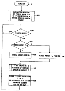
[Fig. 5] An operational flowchart of the reinforcing bar
tying tool.
[ Fig. 6] A graph showing a driving current in a tie wire cutting
step.
[Explanation of Reference Numerals]
1 reinforcing bar tying tool
2 casing
3 tie wire feeding mechanism
4 tie wire twisting mechanism
5 grip portion
6 magazine
7 battery pack
8 power supply switch
9 alarm detection LED
10 twisting torque setting dial
11 tie wire guide nose
6
CA 02595078 2007-07-17
12 trigger lever
13 feed motor
14 V-grooved driving gear
15 V-grooved driven gear
19 rotary cutter
20 pin
21 cutter lever
R reinforcing bar
W tie wire
Best Mode for Carrying Out the Invention
An embodiment of the invention willbe describedwith reference
to the drawings.
[Embodiment 11
Fig. 1 shows a reinforcing bar tying tool 1, and a tie wire
feeding mechanism 3 and a tie wire twisting mechanism 4 are
accommodated inside a casing 2. Atie wire reel (not shown) is loaded
inside a magazine 6 disposed on a front side of the grip portion
5 of the casing 2. A battery pack 7 accommodating an NiMH battery
is attached to an end portion of the grip portion 5, and supplies
electric power to a feed motor of the tie wire feeding mechanism
3 and a twist motor of the tie wire twisting mechanism 4 via a power
supply circuit board (not shown) . A power supply switch 8, an alarm
detection LED 9 and a twisting torque setting dial 10 are disposed
on an upper surface of a rear portion of the reinforcing bar tying
7
CA 02595078 2007-07-17
tool 1, an alarm detection buzzer (not shown) is accommodated inside
the casing 2.
When the battery pack 7 is attached to the reinforcing bar
tying tool 1 and the power supply switch 8 is turned on, the reinforcing
bar tying tool 1 executes an initializing operation, whereby the
tie wire feeding mechanism 3 feeds the tie wire by a certain length
toward a tie wire guide nose 11 disposed on an upper side, and a
rotary cutter o f a tie wire cutting mechanism, which will be described
later, cuts a tip end portion of the tie wire to position a tip
end of the tie wire. The tie wire twisting mechanism 4 performs
a series of operations including a clamping operation and a twisting
operation in a state in which the tie wire is not clamped, and then
stops at its initial position and is placed in a standby state.
After being placed in the standby state, and once a trigger lever
12 is pulled, one cycle of a reinforcingbar tying operation including
a tie wire feeding, a tie wire clamping, a tie wire pulling back,
a tie wire cutting and a tie wire twisting is continuously executed.
A control portion (not shown) monitors a voltage of the battery
pack 7 during the tying operation via a voltage detection circuit,
and when the voltage of the battery pack 7 reduces to a predetermined
charge recommendation voltage, the control portion sounds a buzzer
and lights the alarm detection LED 9 to notify the voltage reduction.
Further, the control portion monitors a driving current of the twist
motor during the tying operation via the current detection circuit
serving as a driving load detecting device, and controls a tie wire
8
CA 02595078 2007-07-17
feeding amount, which will be described later, in accordance with
a current value at the time when the tie wire cutting mechanism
driven by the twist motor performs the cutting operation.
As shown in Fig. 2 (a), the tiewire feedingmechanism3 includes
a V-grooved driving gear 14 driven by a feed motor 13, and a V-grooved
driven gear 15 engaging with the V-grooved driving gear 14, and
is configured in such a manner that the V-grooved driving gear 14
and the V-grooved driven gear 15 clamp and feed the tie wire. The
tie wire W is fed out upwardly from a tie wire reel inside the magaz ine .
The tie wire W thus fed out is formed in an arc shape along the
guide groove on an inner periphery of the tie wire guide nose 11
shown in Fig. 1, and goes around an outer periphery of reinforcing
bars R, and the tip end of the tie wire passes between clamps of
the tie wire twisting mechanism 4.
As shown in Figs. 2(a) and 2(b), the V-grooved driven gear
15 is attached to a lever 16, and is elastically brought in contact
with the V-grooved driving gear 14 by a spring force of a compression
coil spring 17 attached to the lever 16. When a lower end portion
of the lever 16 is pushed toward a center side (a left side in Fig.
2(a)), the V-grooved driven gear 15 attached to an upper portion
of the lever 16 moves away from the V-grooved driving gear 14 disposed
on a side of the feed motor 13, whereby the tie wire W can be passed
between the V-grooved driving gear 14 and the V-grooved driven gear
15. A tie wire guide 18 of a funnel shape is provided beneath a
centerportionbetween the V-grooved driving gear 14 andthe V-grooved
9
CA 02595078 2007-07-17
driven gear 15, so that the tie wire W is passed through the tie
wire guide 18 from below and is set between the V-grooved driving
gear 14 and the V-grooved driven gear 15.
A rotary cutter 19 which cuts a tie wire is disposed above
the tie wire feeding mechanism 3. The rotary cutter 19 has a known
including a pin 20 of a column shape formed with a groove along
its diameter direction, and a cutter lever 21 fitted to the pin
20. A cutter portion 21a corresponding to the groove of the pin
20 is formed at a portion where the cutter lever 21 is fitted to
the pin, and when the cutter lever 21 is rotated with the tie wire
being passed through the groove of the pin 20, the cutter portion
21a of the cutter lever 21 cuts the tie wire W at an outer peripheral
position of the pin 20.
Although not shown, an end portion of the cutter lever 21
is coupled to a slider of the tie wire twisting mechanism 4 via
a link, and the end portion of the cutter lever 21 rotates from
its initial position shown in Fig. 2(b) in a direction shown by
an arrow interlockingly with a movement of the tie wire twisting
mechanism 4 to cut the tie wire, and returns to the initial position
interlockingly with the tie wire twisting mechanism after the cutting
of the tie wire as shown in Fig. 3.
The tie wire twistingmechanism4 is a known mechanism including
a twist shaft not shown in Fig. 1, and three clamp plates attached
to an end of the twist shaft. The three clamp plates is disposed
at an inner side of a side cover 23 located between the tie wire
CA 02595078 2007-07-17
guide nose 11 and a lower side guard 22, and two of the clamp plates
disposed on respective sides of a fixed center clamp plate are opened
and closed by a cam mechanism.
The tie wire is fed out through a space between the center
clamp plate and one of the outer side clamp plates. The control
portion stops the feeding of the tie wire after feeding the tie
wire by a length corresponding to a set number of turns, whereat
the tip end of the tie wire reaches a predetermined position at
the tie wire guide nose 11. Then, the clamp plates of the tie wire
twisting mechanism 4 clamp the tip end side of the tie wire loop
and pull the tie wire back, and at the same time, the tie wire twisting
mechanism 4 slides so that the cutter lever 21 of the tie wire cutting
mechanism is rotated via the link to cut the rear end of the tie
wire loop, whereby the tie wire loop is separated from the succeeding
tie wire. Subsequently, the clamp plates of the tie wire twisting
mechanism 4 also clamp the rear end side of the tie wire loop, and
twists the tie wire loop by rotating the twist shaft and the clamp
plates, so that the reinforcing bars are tied together, and the
twisting operation is stopped when the twisting torque of the twist
motor reaches up to a certain set value. Thereafter, the twist motor
is rotated reversely to open the clamp plates to return the twist
shaft to its initial position, wherebyone cycle of the tying operation
is completed.
After the initializing operation at the time when turning-on
of the power supply, and after the normal tying operation, the tip
11
CA 02595078 2007-07-17
, ' .
end of the tie wire W on a side of the reel is positioned at the
outer peripheral position of the pin 20 of the rotary cutter 19
as shown in Fig. 3. However, in a case where the clamp of the tie
wire twist mechanism failed to clamp the tip end of the tie wire
after the feeding of the tie wire, the tie wire W is pulled back
by a length equal to or larger than a fed length upon the tie wire
pulling back step after the tie wire feeding step. Thus, as shown
inFigs. 4(a) and 4(b) , the tip end of the tie wire W ismovedbackward
than the predetermined position shown in Fig. 3. As described as
the problem of the background art, there is a trouble in the tying
operation of the subsequent cycle in such a case.
A countermeasure of the present invention against this problem
will be explained in accordance with a flowchart shown in Fig. 5.
When the tie wire W is passed between the V-grooved driving gear
14 and the V-grooved driven gear 15 of the tie wire feeding mechanism
and the power supply switch 8 is turned on (step 101) , the control
portion of the reinforcing bar tying tool 1 executes the initializing
operation (step 102) . At this time, the tie wire feeding mechanism
3 slightly feeds the tie wire W, and the tie wire W is cut at the
predeterminedposition as shown in Fig. 4, while the tie wire twisting
mechanism 4 executes the clamping and twisting operations in a state
in which the tie wire is not supplied, whereby all the mechanisms
are stopped at their initial positions, and are placed in the standby
state.
As described above, the control portion monitors the driving
12
CA 02595078 2007-07-17
current of the twist motor via the current detection circuit, and
determines whether it is a cutting operation or a lost operation
in which the tie wire is not passed through the rotary cutter 19,
in accordance with a current value at the time when the rotary cutter
19 driven by the twist motor performs the cutting operation. The
control portion writes "1" as a feeding amount flag in a RAM when
the cutting operation is detected, and writes "0" as the feeding
amount flag in the RAM in a case of a non-cutting operation. A graph
in Fig. 6 shows the driving current of the twist motor. As shown
in the graph, a high current peak appears due to a shearing resistance
at the time of cutting of the tie wire. In contrast, when it is
an abnormal state (the case of the non-cutting operation), a high
current peak does not appear and the graph shows a flat current
line since there is no shearing resistance of the tie wire. The
control portion determines whether the operation is normal or
abnormal in accordance with a presence or an absence of such a peak.
A cutting determination reference value for determining the cutting
operation is predetermined in accordance with a verification result
of measuring the current at the time of an actual operation.
When the trigger lever 12 is turned on in the standby state
after the execution of the initialization (step 103), the tie wire
feeding amount control is executed in such a manner that the tie
wire feeding amount of the tie wire feeding mechanism 3 is controlled
based on the feeding amount flag (step 104). Right after the
initialization, the feeding amount flag is "1" which represents
13
.
CA 02595078 2007-07-17
the normal state so that the tie wire is fed by a regular amount
(step 105), whereby the series of the tying operation is executed
in which the tie wire twisting mechanism 4 clamps the tip end portion
of the tie wire, the tie wire feeding mechanism is driven reversely
to pull back the tie wire, the rear end portion of the tie wire
is clamped, the tie wire cutting mechanism performs the cutting,
and then the tie wire twisting mechanism performs the twisting (step
107).
It is determined whether the rotary cutter 19 has cut the
tie wire or the lost operation is executed in accordance with the
presence or the absence of the prescribed peak of the driving current
of the twist motor during the tying operation, and the feeding amount
flag "1" (the normal state) or "0" (the abnormal state) is recorded
accordingly, and is placed in the standby state.
When an abnormal state arises in which the tie wire twisting
mechanism 4 failed to clamp the tie wire W after the feeding of
the tie wire and the tie wire W is pulled back to the predetermined
position or more as shown in Fig. 4, the rotary cutter 19 cannot
cut the tie wire so it performs the lost operation. Since the
predetermined peak of the twist motor driving current does not appear
in this case, the feeding amount flag "0" is written in step 108.
When the trigger lever 12 is turned on in the subsequent operation,
the process proceeds from step 103 to step 106 in accordance with
the feeding amount flag "0", whereby an amount obtained by adding
a predetermined amount a (a difference L between the predetermined
14
CA 02595078 2007-07-17
. . ' ~
position shown in the figure and the pulled back position) to the
normal feeding amount is fed. Thus, the tip end of the tie wire
W passes between the clamps of the tie wire twisting mechanism 4
and is clamped normally, whereby a manual resetting work of the
tie wire can be eliminated, unless there is a remarkable deformation
or damage in the tie wire W.
Meanwhile, although the configuration in which the driving
load detecting device detects the load amount fro, the current value,
instead of such a configuration, a driving load detecting device
may be configured to detect the load amount from a voltage or a
rotation speed of the twist motor, and various modification may
be made within the technical scope of the invention. It is apparent
that the invention covers such modifications.
Although the invention is explained with reference to a
particular embodiment, it will be obvious for those skilled in the
art that various changes and modifications may be made without
departing from the scope and spirit of the invention.
The present application is based on Japanese Patent
Application (Japanese Patent Application No. 2005-012209) filed
on January 20, 2005, the content of which is incorporated herein
by reference.
Industrial Applicability
In a reinforcing bar tying tool in which a tie wire wound
around reinforcing bars is pulled back to place in a closely contact
CA 02595078 2007-07-17
state and is twisted thereafter to tie the reinforcing bars, the
subsequent tie wire feeding operation can be performed normally
even in a case where the tip end of the biding wire is failed to
be clamped so that the tie wire is pulled back excessively.
16