Note: Descriptions are shown in the official language in which they were submitted.
CA 02595206 2007-07-18
WO 2006/083558 PCT/US2006/001739
FIRE FIGHTING SYSTEM
PRIORITY CLAIM
This application claims priority to and the benefit of U.S. Provisional
Application Serial No. 60/650,335, filed February 4, 2005, and U.S.
Provisional
Application Serial No. 60/697,261, filed July 7, 2005, U.S. Application Serial
No. 11/299,866, filed December 12, 2005, the entire contents of which are
incorporated herein.
BACKGROUND
Fires in high rise buildings cause significant loss of life and millions of
dollars in damage. Such loss and damage is primarily due to the difficulties
associated with fighting and controlling fires in these buildings.
Specifically,
the height of high rise buildings poses unique challenges to firefighters and
significantly limits key firefighting strategies.
Typically in high rise building fires, people become trapped on higher
floors because fires on lower floors prevent a safe exit from the building.
Unfortunately, rescuing people trapped by a high rise fires using ladders is
virtually eliminated because the ladders are too short to reach the higher
floors. Furthermore, in some situations, people trapped in these fires cannot
wait to be rescued due to the extreme heat and smoke generated by the fire
and therefore have no choice but to jump from the high rise building.
High-rise buildings also minimize, if not eliminate, the ability of
firefighters to extinguish a fire with an outside water stream because the
water
streams can only reach a limited distance above the ground. As a result, other
fire extinguishing means must be used to fight high rise fires.
One strategy used by firefighters to attack a high rise fire and to rescue
people trapped by the fire is to attack the fire from within the high rise
building.
In these situations, firefighters use internal stairways to access a fire and
attempt to extinguish the fire using hoses while moving through substantial
CA 02595206 2007-07-18
WO 2006/083558 PCT/US2006/001739
2
heat and smoke. However, this strategy is both time-consuming and
dangerous to firefighters.
Another strategy is to use helicopters to assist with high rise fires.
Helicopters are sometimes used to rescue people trapped on the higher floors
using baskets or stretchers attached to a rope or cable which is lowered down
to the trapped people. However, such efforts are very difficult to coordinate
due to inclement weather conditions, wind conditions and the location of the
trapped people. Furthermore, helicopters are generally not able to help fight
high rise fires by dropping water on the fires, such as with forest fires, due
to
the configuration and congested location of high rise buildings. As a result,
helicopters are typically not used to fight these types of fires.
High rise fires pose several challenges for firefighters because these
fires are difficult to access, control and eliminate, and significantly limit
the
firefighting equipment and techniques available to firefighters for fighting
these
fires.
Accordingly, there is a need for a firefighting system which enables
firefighters to quickly and efficiently control and eliminate high rise fires
and
safely rescue people trapped by these fires.
SUMMARY
The present invention is directed to a firefighting system and, more
specifically, to an apparatus, method and system for fighting high rise fires
including an interchangeable container transportable by a helicopter to a
location of a fire to help fight the fire and rescue people trapped by the
fire.
One embodiment of the present invention provides a firefighting system
including a helicopter, a securing mechanism connected to the helicopter and
a housing defining a receptacle for storing a fire suppressant material. The
housing includes a plurality of securing devices, each of the securing devices
being engageable by the securing mechanism to secure the housing to the
helicopter for transport to a location of a fire such as in a high rise
building. At
least one cannon is connected to the housing. The cannon is automatically
CA 02595206 2007-07-18
WO 2006/083558 PCT/US2006/001739
3
extendable from the housing and operable to emit at least a portion of the
fire
suppressant material on the fire.
In an embodiment, the cannon includes a plurality of telescoping
sections to provide the extendability feature of the cannon.
In another embodiment, the cannon is automatically coupled to the
housing when the housing is connected to the helicopter. This operation
minimizes the amount of time associated with securing the containers or
housings to the helicopter which is critical in fighting fires.
In an embodiment, the fire suppressant material includes at least one of
the materials selected from the group consisting of: water and halon gas.
In another embodiment, the system includes a suction device or snorkel
connected to the housing. The suction device is operable to transport a fire
suppressant material from a source of the fire suppressant material to the
housing.
In a further embodiment, the system includes a door movably connected
to a bottom surface of the housing, wherein the door is operable to move
between a closed position and a substantially open position to enable the fire
suppressant material stored in the housing to be dropped onto the fire.
In an embodiment, the helicopter includes at least one actuator in
communication with the housing. The actuator is operable to adjust at least
one of the extension, elevation and azimuth of the cannon.
In another embodiment, the system includes at least one sensor
connected to the helicopter. The sensor is operable to determine a plurality
of
operational parameters associated with the helicopter. In this embodiment, the
sensor includes at least one of the sensors selected from the group consisting
of: a force transducer, an accelerometer and a gyroscopic device.
In an embodiment, the system includes a plurality of housings, where
each of the housings defines a receptacle for storing a fire suppressant
material. Each of the housings are also engageable by the securing
mechanism to interchangeably secure each of the housings to the helicopter
for transport to the location of the fire.
CA 02595206 2007-07-18
WO 2006/083558 PCT/US2006/001739
4
Another embodiment of the present invention provides a firefighting
system including a helicopter, a securing mechanism connected to the
helicopter and a housing including a cannon. The housing includes a plurality
of securing devices, where each of the securing devices is engageable by the
securing mechanism to secure the housing to the helicopter for transport to a
location of a fire. At least one canister is stored in the housing. The
canister
includes a fire suppressant material, where the cannon is operable to eject
the
canister from the housing to the location of the fire.
In an embodiment, the housing includes a plurality of cannons. Each of
the cannons are operable to eject one of a plurality of canisters stored in
the
housing.
In another embodiment, the system includes a solid propellant
connected to the canister to propel the canister from the housing via the
cannon.
In an embodiment, the cannon includes a plurality of telescoping
sections to provide the extendability feature of the cannon.
In another embodiment, the helicopter includes at least one actuator in
communication with the housing. The actuator is operable to adjust at least
one of the extension, elevation and azimuth of each of the cannons.
In an embodiment, the system includes a plurality of housings. Each of
the housings including at least one extendable cannon and a plurality of
canisters containing a fire suppressant material. The housings are each
engageable by the securing mechanism to interchangeably secure each of the
housings to the helicopter for transport to the location of the fire.
A further embodiment of the present invention provides a firefighting
system including a helicopter, a securing mechanism connected to the
helicopter and a housing adapted to hold at least one person. The housing
includes a plurality of securing devices, where each of the securing devices
is
engageable by the securing mechanism to secure the housing to the helicopter
for transport to a location of a fire.
In an embodiment, at least one door is movably connected to the
housing to enable the person to access the housing.
CA 02595206 2007-07-18
WO 2006/083558 PCT/US2006/001739
In another embodiment, a ramp is connected to the housing. The ramp
is positioned adjacent to the door and operable to automatically extend from
the housing to enable the person to move from the location of the fire to the
housing. The ramp is constructed to support the weight of the person.
5 In an embodiment, the ramp includes a plurality of telescoping sections,
where each of the sections includes a platform and a handrail to provide
support for the person moving from the location of the fire to the housing.
In another embodiment, the system includes at least one counterweight
connected to the housing. The counterweight being automatically extendable
from a side of the housing opposite to the side including the ramp to
counteract
a moment generated by the weights of the person and the ramp.
In an embodiment, the housing is adapted to hold a plurality of people,
where the ramp is constructed to support at least the combined weight of the
people moving on the ramp from the location of the fire to the housing.
In another embodiment, the system includes at least a first
counterweight movably connected to the housing. The first counterweight is
operable to automatically extend a distance from the housing to counteract a
moment generated by the combined weight of the ramp and the person.
In an embodiment, a second counterweight is connected to one of the
housing and the first counterweight to counteract the moment generated by the
combined weight of the ramp and the person.
In another embodiment, the system includes at least one force sensor
connected to the helicopter. The force sensor operable to calculate the
moment created by the weight of the ramp and the person, wherein the first
counterweight is automatically extended from the housing based on the
moment calculated by the sensor.
In an embodiment, the system includes an extendable canopy
connected to the ramp. The canopy is adapted to protect the person moving
on the ramp from falling debris generated by the fire.
In another embodiment, the housing includes emergency medical
equipment used to treat a person injured by the fire.
CA 02595206 2007-07-18
WO 2006/083558 PCT/US2006/001739
6
In a further embodiment, the system includes at least one generator
coupled to the helicopter. The generator is operable to generate electricity
for
the housing, where the housing is automatically coupled to the generator when
the housing is connected to the helicopter.
In an embodiment, the housing is adapted to be secured to a truck to
transport any injured people from the location of the fire to an emergency
medical facility.
Another embodiment of the present invention provides a method of
operating a firefighting system. The method includes securing a container to a
helicopter having a securing mechanism and at least one control mechanism.
The container includes a plurality of securing devices, where each of the
securing devices is engageable by the securing mechanism to secure the
housing to the helicopter for transport to a location of a fire. The method
includes automatically coupling the control mechanism to the container, where
the control mechanism is operable to communicate with the container and
control a function of the container. The method also includes transporting the
container to a location of a fire.
In an embodiment, the method includes automatically extending a
cannon connected to the housing. The cannon is operable to emit a fire
suppressant material stored in the container on the fire.
In another embodiment, the function includes ejecting a canister
containing a fire suppressant material from a cannon connected to the
container to the location of the fire.
In a further embodiment, the function includes automatically extending a
walkway movably connected to the housing. The housing is adapted to hold at
least one person. The walkway is adapted to support the weight of the person.
In an embodiment, the method includes automatically extending a first
counterweight from a side opposite to the side of the housing including the
walkway. The first counterweight is automatically extended from the housing
based on a distance the walkway is extended from the housing.
CA 02595206 2007-07-18
WO 2006/083558 PCT/US2006/001739
7
In another embodiment, the method includes automatically extending a
second counterweight from the housing based on the distance that the first
counterweight and the walkway are extended from the housing.
It is therefore an advantage of the present invention to provide a
firefighting system and apparatus which helps firefighters suppress and
control
fires in high places.
Another advantage of the present invention is to provide a firefighting
system and apparatus which is used to safely rescue one or more people
trapped by fires in high places.
It is a further advantage of the present invention to provide a firefighting
system and apparatus which quickly and efficiently suppresses and controls
fires in high places.
It is another advantage of the present invention to provide a firefighting
system and apparatus which minimizes firefighters risk of injury and death due
to fires in high places.
It is a further advantage of the present invention to provide a firefighting
system and apparatus which employs interchangeable containers that are
easily transportable by a helicopter or other vehicle to the location of a
fire or
other disaster.
Other objects, features and advantages of the invention will be apparent
from the following detailed disclosure, taken in conjunction with the
accompanying sheets of drawings, wherein like numerals refer to like parts,
elements, components, steps and processes.
DESCRIPTION OF THE FIGURES
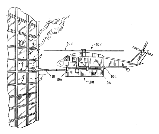
Fig. 1 is a perspective view of a helicopter carrying a container
according to one embodiment of the present invention.
Fig. 2A is a perspective view of the embodiment of the container
illustrated in Fig. 1.
CA 02595206 2007-07-18
WO 2006/083558 PCT/US2006/001739
8
Fig. 3A is a front view of one embodiment of a latch connected to the
container shown in Fig. 2A.
Fig. 3B is a cross section view of the latch taken substantially along line
3B-3B in Fig. 3A.
Fig. 4 is a perspective view of a wedge utilized by a securing
mechanism connected to the helicopter to engage and hold the container
shown in Fig. 2A.
Fig. 5 is a perspective view of another embodiment of the present
invention where the container includes a suction member.
Fig. 6 is a perspective view of a helicopter carrying a container
according to another embodiment of the present invention where the container
includes fire suppressant canisters.
Fig. 7 is a perspective view of the container shown in Fig. 6.
Fig. 8 is a diagrammatic view of a canister included in the container of
Fig. 7.
Fig. 9A is a side view of a helicopter carrying a container according to
another embodiment of the present invention where the container is used to
transport people rescued from a fire.
Fig. 9B is a front view of the embodiment illustrated in Fig. 9B.
Fig. 10 is a perspective view of a helicopter carrying a container
according to a further embodiment of the present invention where the container
is used as an emergency medical facility.
Fig. 11 is side view of the container of Fig. 10 where a walkway and
counterweight are at least partially extended from the container.
CA 02595206 2007-07-18
WO 2006/083558 PCT/US2006/001739
9
Fig. 12 is a side view of a vehicle used to transport the container of Fig.
10.
DETAILED DESCRIPTION
Referring now to Figs. 1-4, a firefighting system of the present invention
is illustrated where the firefighting system includes a container or pod 100
which is designed to hold water or a suitable fire suppressant that can be
transported to a high rise fire or other high places such as by helicopter to
help
reduce and eliminate a fire in a high rise building. The firefighting system
therefore enables firefighters to better combat fires in high rise buildings
and
significantly reduce the loss of life and damage caused by these fires.
The firefighting system shown in Fig. 1 includes a container or pod 100
of fire-fighting foam, water or other suitable fire suppressant, attached to a
multi-purpose lift or securing mechanism 104, which is attached to a
transporter such as helicopter 102. It should be appreciated that the
transporter or helicopter may be any suitable helicopter such as helicopters
102 and 402 in Figs. I and 9A, respectively, or any suitable air transporter
or
air transportation vehicle. In the illustrated embodiment, when the helicopter
latches on to the multi-purpose securing mechanism, a power connection is
automatically coupled to a suitable electric power source such as an electric
generator on the helicopter. The power source provides power for the systems
on the container.
In the illustrated embodiment, the container or pod 100 includes a
housing 108 that is generally rectangular in shape having a base or bottom
portion 116 and four side walls 112 which extend generally upwardly from the
base 116. A top wall or top surface 114 is attached to the top edges or top
surfaces of each of the side walls opposite to the base 116. The base 116,
four side walls 112 and top wall 114 form the housing and define an interior
space or receptacle for receiving and storing a fire suppressant such as water
or other suitable fire suppressant.
As shown in Figure 1, the container or pod 100 is latched to a container
of fire-fighting foam, water or other suitable suppressant. The container also
CA 02595206 2007-07-18
WO 2006/083558 PCT/US2006/001739
contains an extendable water cannon. The inlet to the water cannon is
automatically coupled to the foam container when the attachment is latched to
the foam container. The extendable water cannon can be extended as
required and can be adjusted in elevation and/or azimuth as required to direct
5 the foam stream effectively to the fire. Suitable actuators powered by the
attachment electrical system provide the required motions for extension,
elevation, and azimuth corrections. These motions are controlled by an
operator in the helicopter who uses an on-board electronic system to control
the functions of the helicopter and the container.
10 The on-board electronic system contains electronic sensors such as
force transducers, accelerometers, gyroscopic devices and other suitable
sensors. These devices are in communication with the electronic system and
provide stability correction signals to the helicopter flight control system
to
counteract the destabilizing effects of changes in center of gravity due to
the
emptying of the container, extending and aiming the water cannon, reaction to
the thrust of the foam stream, wind forces on the container, and other
destabilizing influences.
The containers described above can be pre-positioned at suitable
locations so that the helicopter can be deployed quickly to latch on to a
container and attack the fire. While the helicopter is fighting the fire with
the
first container, other containers from land-based storage areas can be brought
to the scene by truck or other means so that a continuous supply of foam
containers is available to fight the fire. If the land-based containers do not
arrive quickly enough, the helicopter can retrieve another container from one
of
the pre-positioned locations. Since most helicopters have speeds in excess of
100 miles per hour, the retrieval of additional containers from pre-positioned
locations can be accomplished quickly.
A plurality of latch members or latches 126 are securely connected to
the housing 108. The latches 126 may be welded onto the housing, integrally
formed with the housing or secured to the housing in any suitable manner.
Each latch 126 includes an upper receptacle 128 and a lower receptacle 130.
The upper receptacle 128 is defined by or formed in the latch 126 and has a
CA 02595206 2007-07-18
WO 2006/083558 PCT/US2006/001739
11
generally triangular shape. The lower receptacle 130 has a generally
rectangular shape and is defined by or formed in latch 126 and positioned
below the upper receptacle 128. The upper and lower receptacles 128 and
130 defined by each of the latches 126 are adapted to engage and be securely
held by a securing mechanism 104 as illustrated in Fig. 1.
The securing mechanism 104 can be any suitable mechanism such as
the securing mechanism or lift described by U.S. Patent No. 5,573,293,
assigned to Mi-Jack Products, Inc., which is incorporated herein by reference.
The securing mechanism 104 includes four lift devices or securing devices 132
which correspond in position to each of the latches 126 on the housing 128.
As shown in Figs. 3A, 3B and 4, the securing devices 132 include a first end
134 which defines a circular opening or channel. The opening or channel is
sized to engage a corresponding post or pole of the securing mechanism 104.
The opening or channel on first end 134 thereby enables the securing device
to pivot about the post and be adjusted to securely engage the lower
receptacle 130 of each of the latches. Securing device 132 also defines
elongated openings or slots 136 which help support the securing device and
enable the position of the securing device to be adjusted as needed. A second
end 138 of the securing device, which is opposite to the first end 134,
includes
at least one hook member or hook 140. The hook member or hook 140
includes a generally angular surface which is sized to engage the lower
receptacle 130 of each of the latches 126. It should be appreciated that any
suitable securing device or devices may be used to engage and securing the
containers 100.
Referring now to Figs. 3A and 4, each securing device 132 is positioned
to correspond to the positions of the latches 126 on the containers or pods
100. When the securing devices are positioned or moved adjacent to the
latches, the positions of the securing devices 132 are adjusted as necessary
to
align and engage the securing devices with the lower receptacles 130 of the
latches. The securing devices engage the lower receptacles 130 of each latch
126 and, more specifically, the hook 140 of each securing device engages
and pushes upwardly on indent 140 of the lower receptacle 130 of each latch.
CA 02595206 2007-07-18
WO 2006/083558 PCT/US2006/001739
12
The engaging action or upward force of the hook 140 against the indent of
each of the latches 126 enables a transport device such as a helicopter to
engage the container and upwardly support the container or pod 100.
In the illustrated embodiment shown in Figs. I and 2, the container or
pod 100 includes an extendable nozzle or a cannon 110. The extendable
cannon 110 includes a plurality of sections or tubes such as first tube 120,
second tube 122, and third tube 124. The third tube 124 slidingly engages
second tube 122 and are adapted to each be slidingly engaged with or
received by first tube 120. The three tubes, and specifically the first tube
120,
are slidingly engaged with an opening 118 defined by the housing 108 of the
container or pod 100. Therefore during transport or non-use, the first, second
and third sections or tubes 120, 122 and 124, respectively, of the extendable
cannon 110 are retracted or moved within housing 108. An electrical
connector such as suitable wiring cable or other suitable connector, is
attached
between the securing mechanism 104 and the container or pod 100. The
electrical connection is made when the pod is initially picked up by a
helicopter
or other airborne device. It should be appreciated that the electrical
connection between the container and the securing mechanism may be
performed manually or automatically.
In the illustrated embodiment, the helicopter pilot or other member of the
crew activates a button or switch to cause the extendable cannon to move
outwardly away from the housing 108. After the cannon 110 is fully extended,
the pilot activates the same or a different button or switch to cause the
cannon
110 to emit a continuous stream of water or other fire suppressant at a
designated rate and pressure. It should be appreciated that any suitable rate,
pressure or pressures may be employed to emit the water or fire suppressant
from the extendable cannon 110. It should also be appreciated that the
cannon 110 may be any suitable size or shape or have any suitable number of
sections or tubes that slidingly engage within each other to form the cannon.
As illustrated in Fig. 1, the container or pod 100 is secured by securing
mechanism 104 and secured to the bottom of an air transport vehicle such as
a helicopter 102 having blades or rotors 103. The containers 100 can be pre-
CA 02595206 2007-07-18
WO 2006/083558 PCT/US2006/001739
13
positioned at suitable locations so that the helicopter can be deployed
quickly
to latch on to a container and attack the fire. While the helicopter is
fighting the
fire with the first container, other containers such as those used for land-
based
storage areas can be brought to the scene by truck so that a continuous supply
of fire suppressant or foam containers is available to fight the fire. If the
land-
based containers to not arrive quickly enough, the helicopter can retrieve
another container from one of the pre-positioned locations. Since most
helicopters have speeds in excess of 100 mph, the retrieval of additional
containers from pre-positioned locations can be accomplished quickly.
In the illustrated embodiment, the container or pod 100 is positioned
beneath the helicopter 102 to enable the helicopter to freely move from side
to
side or forward or backward as needed. The container or pod 100 is also
positioned and connected to the bottom of the helicopter opposite to the
blades
and rotors 103 so that the pod 108 will not interfere with the blades or
rotors
103 or any other portions of the helicopter. Fig. 1 illustrates how a
continuous
stream of water or fire suppressant under a designated pressure is emitted or
discharged from the water cannon 110 toward a fire in a high rise building or
other high area. The container or pod 100 therefore enables users such as
firefighters to quickly reach a fire in a high rise building or other high
area and
direct water or any other suitable fire suppressant from an airborne vehicle
such as a helicopter onto the fire. The container 100 also enables
firefighters
to be able to combat fires in high rise buildings by gaining external access
to
those areas where such access was not previously available.
Referring now to Fig. 5, another embodiment or variation of the fire-
fighting system of the present invention is illustrated. In this embodiment, a
detachable water tank or container 200 is attached to the multi-purpose
securing mechanism or attachment device 204. The attachment means and
coupling devices are as previously described.
The container 200 includes a housing 208 having a bottom wall and four
side walls extending generally upwardly from the bottom wall and a top wall as
shown previously in Fig. 2. The housing is connected to a securing
mechanism 204 using connectors 206 as described above. The container
CA 02595206 2007-07-18
WO 2006/083558 PCT/US2006/001739
14
includes a water cannon 210 that emits water or other suitable fire
suppressants from the housing 208.
A re-fill snorkel or suction device 212 is connected to the bottom wall or
bottom surface of the housing 208. The suction device 212 can be any
suitable suction device or devices. The suction device 212 includes a shaft
214 which may be rigid or flexible, such as a hose, and a nozzle 216 secured
to one end of the shaft 214. The other end of the shaft 214 is securely
connected to the bottom of the housing 208. The suction device or snorkel is
attached to a motor or other suitable actuator in the housing 208 to generate
a
vacuum or suction like effect through the nozzle 216 and the shaft 214. The
suction through the shaft and therefore the nozzle 216 enables the suction
device to be able to suck up a liquid such as water or other fluid to the
housing
208 after the shaft 214 and nozzle 216 are at least partially submerged in a
liquid such as water or other suitable fire suppressant.
The container 200 can therefore be refilled by having the helicopter
hover over a water source such as a pond, river, lake or similar body of water
and submerging the snorkel below the water surface. Water or a mixture of
water and foam from an on-board foam container (not shown) can be directed
to the fire by the extendable water cannon as described above. Additionally, a
bottom-drop door (not shown) is provided so that the container contents can be
dropped directly onto a fire if there is a need to do so such as with a roof
fire.
Referring now to Figs. 6 and 7, a further embodiment of the firefighting
system is illustrated. In this embodiment, a container 300 is configured to
direct or project halon shells or canisters 326, or canisters including other
suitable oxygen depletion or flame retardant substances , into a fire to help
control and extinguish the fire.
In this embodiment, the firefighting system includes a container or pod
300 having a generally rectangular shaped housing 308. The housing 308
includes a bottom wall and side walls which extend generally upwardly from
the bottom wall. A top wall or top surface is connected to the top edges of
the
four side walls to form the housing and define an interior space or
receptacle.
The housing 308 includes a plurality of connectors or latches 306 which
CA 02595206 2007-07-18
WO 2006/083558 PCT/US2006/001739
engage hook members or hooks 132 as described above of a securing
mechanism 304 which secures the container or pod 300 to the bottom of a
helicopter 302 to securely hold the container or pod 300.
The housing 308 defines at least one and preferably a plurality of
5 ejector channels, tunnels or tubes 322. In an embodiment, the ejector tubes
322 automatically extend from the container based on a control input from a
pilot or other operator. The ejector tubes 322 may be any suitable size or
shape. In the illustrated embodiment, the ejector tubes 322 are sized to hold
and eject the shells or canisters 326 as shown in Fig. 8. Each ejector tube
322
10 may eject one or more of the canisters 326. Generally, each of the ejector
tubes 322 and the housing 308 are sized to store a plurality of canisters 324
but also to maintain the housing 308 of the container or pod at a suitable
size
and shape to be air secured or moved by an airborne vehicle such as a
helicopter.
15 In another embodiment, the container 300 includes an extendable
cannon (not shown) which includes one or more stages or sections and is
automatically extended from the container. The cannon is extended and
moved as required in elevation and azimuth as described above.
Referring now to Fig. 8, in one embodiment, each canister 324 includes
a housing 326 having generally angled or beveled front surfaces defining an
interior chamber, receptacle or space which holds a fire suppressant such as
halon gas or other suitable type of fire suppressing gas or liquid. The halon
shells are launched to the fire target area by explosive charge, compressed
air
or any other suitable method. In one embodiment, a solid propellant 330 is
connected to each of the canisters 324 to enable the canisters to be ejected
or
emitted from each of the ejection tubes 322 and toward at least a portion of a
fire in a high rise building or other high location. Specifically, each
canister is
ejected from the container at a designated rate and pressure. It should be
appreciated that the canisters may be ejected at any suitable rate and
pressure.
The canisters 324 open and release the contents held inside the
canister upon impact with the building. The shells are launched with
sufficient
CA 02595206 2007-07-18
WO 2006/083558 PCT/US2006/001739
16
force to penetrate windows or relatively thin walls. In another embodiment,
the
shells include a timer or timing mechanism where the contents of the shells
are
released after a designated or predetermined amount of time as set in the
timer. A fire suppressant such as halon gas significantly reduces and/or
eliminates a fire or fires. It should be appreciated that the canisters 324
may
be any suitable size or shape. It should also be appreciated that the solid
propellant 330 may be any suitable propellant for causing the canister 324 to
be emitted or ejected from the ejection tubes 322.
Referring to Fig. 7, in one embodiment, the channels or tubes 322 are
generally circularly shaped and mounted to be initially flush with the front
surface of the housing 308. The tubes 322 are extendable and automatically
extend from the container when an operator such as the pilot of the helicopter
activates an input or button from inside the helicopter. It should be
appreciated
that one or more extendable cannons or tubes 322 may be connected to the
container. Each tube or cannon 322 includes one or more sections which are
extendable from the container 300. A plurality of latches 316 are attached to
the top wall 312 and side walls 310 using a suitable connector or connectors.
As described above, the securing mechanism 304 causes each of the securing
devices 132 to engage the latches 316 and secure the container or pod 300 off
of the ground by a helicopter which remotely controls the emission or ejection
of the water, fire suppressant, or other suitable chemical or materials from
the
container.
Referring now to Figs. 9A and 9B, another embodiment of the
firefighting system of the present invention is illustrated. This system
includes,
a container 400 having an extendable rescue platform or bridge 414 which is
deployed to allow people to escape from a fire by walking on the platform to
the helicopter. In order to maintain stability, a system of force sensors are
used to calculate the moment caused by extending the rescue platform. The
on-board electronic system automatically extends a counter weight to maintain
balance and stability as described below. When a person is walking on the
platform, the platform, the sensors, and electronic system automatically
CA 02595206 2007-07-18
WO 2006/083558 PCT/US2006/001739
17
position a second or secondary extendable counterweight to maintain stability
and balance.
In the illustrated embodiment, the container or pod 400 has a generally
rectangular shape and is sized to hold one or more people. The container or
pod 400 includes a housing 408 which is generally rectangular in shape and
defines a room or area having a suitable height to accommodate people. As
illustrated, the container or pod 400 includes latches 406 which connect with
the securing mechanism 404 to enable the container or pod 400 to be lifted up
underneath the helicopter 402 to be moved or transported to a designated
area. In the illustrated embodiment, the housing 408 includes at least one
door 412. The door 412 is movably or hingedly connected to the housing 408
and swings open to the left or to the right depending on the preferences of
the
manufacturer. It should be appreciated that the housing 408 may be sized to
any suitable size or shape, depending on the particular application. For
example, different sized containers or pods 400 may be made to
accommodate different numbers of people. It should also be appreciated that
the door may be slidably connected to the housing or connected in any
suitable manner.
In the illustrated embodiment, an extendable walkway 414 is contained
within the housing 408 and is automatically extended away from the housing
408 toward a high rise building or other location to attempt to rescue one or
more people trapped in the high rise building. The extendable walkway 414
includes sections, ramp members or stages 416a, 416b, 416c and 416d which
automatically extend toward and away from a side of the housing 408 and
forms the extendable walkway 414 when a control or an input such as a button
is activated by an operator in the helicopter. Each ramp member or stage 416
includes a platform or walking surface 418 made of a suitable metal or other
suitable material. Additionally, each ramp member or stage 416 includes a
handrail or rail 420. The rails 420 provide a surface for a person escaping a
fire to hold onto and helps that person to stably move along the walkway to
get
to the housing 408. It should be appreciated that the extendable walkway 414
may include any suitable number of ramp members or ramp stages 416. It
CA 02595206 2007-07-18
WO 2006/083558 PCT/US2006/001739
18
should also be appreciated that the extendable walkway 414 can extend to any
suitable distance and does not necessarily have to be fully extended to be
operational or usable. It should be further appreciated that the extendable
walkway may extend from either side of the container or from the front or back
of the container as shown in Fig. 11.
At least one counterweight such as first counterweight 422 extends
outwardly away from the housing 408 on a side opposite to the side including
the extendable walkway 414. The counterweight 422 automatically extends
toward and away from the housing as necessary to counter the weight or
rotational force or torque generated by the walkway 414, which depends on the
distance that the walkway is extended from the housing 408. The first
counterweight 422 is extended outwardly away from the housing 408 based on
the distance that the walkway 414 is extended from the housing. Additionally,
one or more second counterweights 424 are attached or connected to the first
counterweight 422 to provide additional weight or counterweights for the
walkway 414 as needed.
In operation, the helicopter operator, who is sitting within the helicopter
402, positions the helicopter so that the securing mechanism can grasp or
latch onto the container or pod 400 which is positioned on the ground or on
top
of a nearby building or buildings. The securing mechanism secures the
container or pod and the helicopter 402 engages, lifts and secures the
container or pod 400 to carry it to a location on a high rise building which
is on
fire or that has people who are trapped and need a way out. The helicopter
operator uses controls connected within the helicopter 402 that send
electrical
signals to the extendable walkway 414 and first and second counterweights
422 and 424 to automatically extend away from the housing 408 a designated
or desired distance. Once extended to the designated or desired distance, the
helicopter operator positions the helicopter 402 close to where the people are
trapped in the high rise building to attempt to rescue those people. The
helicopter operator positions the extended walkway as close to the building as
possible to enable the trapped people to access the walkway 414 and use the
walkway to enter the housing 408 of the container or pod 400.
CA 02595206 2007-07-18
WO 2006/083558 PCT/US2006/001739
19
In one embodiment, one or more sensors or sensing devices such as
position sensors are connected to and positioned on or near the front of the
helicopter 402. Each position sensor is calibrated to provide a warning signal
to the helicopter operator or pilot that the distance between the rotor tip
and a
fixed obstruction such as a building, utility tower or the like is approaching
a
minimum safe value. The minimum safe value may be a pre-programmed or
pre-determined fixed value or may be automatically adjustable to compensate
for such factors as wind velocity, voltage, or power lines or other criteria.
It
should be appreciate that any suitable sensor or sensors may be used to
identify the position of the rotors and/or helicopter.
In another embodiment, the extendable rescue walkway or platform may
also be equipped with an extendable canopy (not shown) to protect people on
the platform from water spray, falling debris such as fragments of broken
glass
from windows or ashes.
Referring now to Figs. 10, 11 and 12, in a further embodiment, the
container 500 is set up as an emergency rescue pod that is installed on a
helicopter 502. The lifting attachment or lift mechanism 504 latches on to the
helicopter, and the emergency rescue pod or container 500 is latched to the
lifting mechanism using latches 506. The container 500 is automatically
coupled to a suitable power source such as a generator on the helicopter. The
latching devices or latches 506 utilized by the lifting attachment or device
504
to latch to the helicopter and the container or emergency rescue pod 500 may
be the Mi-Jack wedge described above or any other suitable devices.
In this embodiment, the emergency rescue pod or container 500
including a housing 508 which is equipped with first aid and life support
equipment such as found in a typical paramedic emergency van. Also, the
emergency rescue pod is equipped with an extendable platform 514 as
described above to allow fire victims to enter or be assisted to enter the
emergency rescue pod. Additionally, emergency personnel such as
firefighters, paramedics and other people can be transported to a particular
part of a building or other high location in the container 500 and then use
the
walkway or platform to access the building.
CA 02595206 2007-07-18
WO 2006/083558 PCT/US2006/001739
In one embodiment, the container or pod 500 includes panels 510 which
securely support and conceal the electrical controls for the housing 508 as
well
as other controls. In the illustrated embodiment, the housing 508 includes at
least one door 512. The door 512 is movably connected to the housing 508
5 and swings open to the left or to the right depending on the preferences of
the
manufacturer.
In order to maintain stability, a system of force sensors is used to
calculate the moment caused by extending the platform. First or primary
counterweights and second or secondary counterweights 522 and 524 are
10 extended on an opposite side to the platform 514 to maintain stability as
described above.
After one or more people are rescued from the high rise building and
are safely inside the container or pod 500, the helicopter operator transfers
the
container or pod 500 to the ground so that the trapped people can be treated
15 by medical staff. Alternatively as described above, doctors, nurses and
other
medical personnel may be transported inside the container or pod 500 to the
fire location to immediately treat fire victims as they enter the housing 508.
Once on the ground, the entire container may be placed on a truck
chassis or other vehicle by the helicopter so that the emergency rescue
20 pod may be driven to a hospital or emergency care facility in the same
way as a paramedic rescue van would be driven to such locations. In the
illustrated embodiment, the helicopter 502 positions or places the container
or
pod 500 onto a suitable moving vehicle such as a truck 526. The housing 508
of the container or pod 500 is securely attached and/or positioned on the
truck.
The truck 526 can then transport the container or pod 500 directly to a
hospital
or other emergency care facility so that the people inside the housing, which
were rescued from the high rise building, can be treated immediately. It
should
be appreciated that the truck 526 may be any suitable vehicle or vehicles for
transporting the container.
The above embodiments describe a multi-facet fire fighting system
in which various special purpose subsystems can be mounted on a
CA 02595206 2007-07-18
WO 2006/083558 PCT/US2006/001739
21
helicopter or other transportation vehicle. Although the subsystems form
a fire fighting system particularly suitable to fighting urban high-rise
fires,
it should be appreciated that the present invention is not limited to such
a use and may be used for other suitable purposes.
While the present invention is described in connection with what is
presently considered to be the most practical and preferred embodiments, it
should be appreciated that the invention is not limited to the disclosed
embodiments, and is intended to cover various modifications and equivalent
arrangements included within the spirit and scope of the claims. Modifications
and variations in the present invention may be made without departing from
the novel aspects of the invention as defined in the claims, and this
application
is limited only by the scope of the claims.