Note: Descriptions are shown in the official language in which they were submitted.
CA 02595296 2010-08-26
1
Method for determining the orientation of an antenna
array
The invention relates to a method for determining the
orientation of an antenna array for a satellite-aided
positioning system and a computer program product.
In the determination of positions or orientations by
means of satellite-aided positioning systems, signals
from satellites are received by antennae or receivers,
from which signals the position of the antennae can be
determined. If these antennae are mounted, for
example, on a vehicle, the position of this vehicle can
be determined. By using a plurality of antennae,
positions thereof and hence further information about
the orientation of the vehicle can be obtained. By
using at least three antennae fixed to vehicles and
having a known geometrical arrangement, it is finally
possible in principle to derive the three-dimensional
orientation of the vehicle provided that the antennae
are not arranged linearly and a connecting line between
two antennae in each case defines a base line.
However, in general arrays comprising 4 antennae are
used since the additional antenna introduces redundancy
and further security into the system. In order to
carry out the sufficiently precise position
determination in the range of the carrier wavelength of
the received signal, phase ambiguities must be resolved
since only a shift of phases is detected by the
antennae. The resolution of this phase ambiguity can
be improved or accelerated by the use of further
CA 02595296 2007-07-19
2
antennae.
Since as a rule signals from at least 4 satellites are
received by at least 3 antennae, a combinatory problem
results. For solving combinatory problems, methods
which can select the optimal solution from the total
number of permissible solutions, for example by means
of least squares fit or of statistical methods, are
used. Since, however, the total number of solutions to
be investigated is as a rule very large and,
particularly in the case of dynamic applications, the
solution of such combinatory problems is very intensive
in terms of computing, there is a need of efficient
design for the algorithms used. Thus, there is
interest in limiting the total number of solutions to
be investigated with the use of available information
as secondary conditions or restrictions, so that
successive candidates can be eliminated from a set of
possible solutions until the remaining solution
determines the position or the orientation.
A suitable possibility for limiting the total number of
candidates to be investigated is the derivation of
restrictions from information known a priori, such as,
for example, the known geometrical arrangement of the
arrays, or from plausibility assumptions, such as, for
example, a maximum limit for the inclination of a
vehicle relative to the horizontal.
Methods for resolving the phase ambiguities are
described, for example, in Euler, H.-J. "GPS Attitude
Determination: Utilizing Auxiliary Information to
obtain Improved Results", 3rd Int. Workshop, "High
CA 02595296 2007-07-19
3
Precision Navigation", 3-5 April 1995, Stuttgart, and
Euler, H.-J., Hill, Craig D., "Attitude Determination:
Exploiting all Information for Optimal Ambiguity
Resolution" ION GPS 95, 12-15 September 1995, Palm
Springs, California.
In these publications, topocentric, i.e. local,
coordinate systems are used for optimal utilization of
known information. In the evaluation or limitation of
the resolution space, the geometry between in each case
two antennae in particular the spacing and height
difference thereof, is used, but the calculation of the
orientation of a base line in three dimensions remains
complicated.
A suitable approach for the successive limitation of
the resolution space is disclosed, for example, in
Hill, Craig D., Euler, H.-J. "Optimal Ambiguity
Resolution Technique for Attitude Determination",
Proceedings of the 1996 IEEE Position Location and
Navigation Symposium, PLANS, Atlanta, GA, USA, pages
263-269.
A conventional base line method is based on the
following system of linearized equations for simple
differences.
A~i2 =dt+(Xidx,+x2dx2+x3dx3)/~.+N'
A 2 = dt+(Xldx, +x202 +x3dx3)/i%+N2
AO =dt+(xidX +x202+x3dX3)lA+N3 (1)
AA4 = dt+(x;dxl +x2dx2 +X3dX3)/i%+N4
CA 02595296 2007-07-19
4
in which
Z\4?112 is the observed simple difference of the
stations 1 and 2 relative to the satellite i,
dt is the receiver clock difference
x1 is the j th component of the unit vector
pointing to the satellite i,
is the wavelength of the carrier phase,
dxj is the j th component of the unknown position
vector of the second antenna and
N1 is the integral phase ambiguity of the simple
difference, coordinated with the satellite i.
This system of 4 equations gives the relative positions
of the phase centres of the two antennae, provided that
the phase ambiguity is resolved or determined. The
respective coordinates can subsequently be transformed
into the orientation of the base line so that, from the
orientation of the antenna array, the orientation of a
body associated therewith can also be derived. Any
integral phase-ambiguity which gives a solution for the
relative coordinates which lies within a sphere having
the radius of the base length is a candidate for the
correct result. In addition, the combination of the -
known - length of the base length with a deviation
which is only minimal is to be reproduced.
If sufficient measurements are available, the phase
.CA 02595296 2007-07-19
ambiguities can be resolved, for example by the least
squares method or methods of integral or mixed integral
optimization.
5 One approach for the successive limitation of the
solution space by elimination of candidates is based on
the abovementioned use of information about the
geometry of the antenna array.
In a topocentric reference system, the vector of the
base line can be described according to
b =(e;n;u) (2)
b = Je2+n2+u2
in which e, n, u are in each case the East, North and
height component of the base line.
In general, the observation equation of the single
difference for the base line between the antennae Al
and A2 can be stated as follows
Sn eSn nSn u Sn Sn
ALi2ZioO1 = e01 3n + n01 m + u01 3n +Li 2L N01 + CLit C (3)
PO PO PO
in which
ALi/L;oo is the simple difference of a carrier phase
measurement for the frequency Li, e.g. the
frequency Ll or L2 of the GPS system, and the
satellite Sn between the antennae AO and Al,
CA 02595296 2007-07-19
6
eoõno,,uo, are the east, north and height component of
the base line between the antennae AO and Al,
esn nsn usn
sn, sn, snare the topocentric unit vectors to the
Po Po Po
satellite Sn,
DA is the wavelength of the frequency Li,
Li NO is the carrier phase ambiguity of the simple
difference for the satellite Sn and the
frequency Li,
c is the velocity of light in a vacuum and
litcol is the time difference of the receiver clocks
for the frequency Li and the base line
between the antennae AO and Al.
With a sufficient number of measurements to satellites,
for example to four satellites in a favourable
configuration, and a choice of suitable values for the
phase ambiguity, the east, north and height component
of the base line can be calculated.
For limiting the solution space, it is now possible to
use the information about the geometry of the antenna
array or plausibility assumptions. For example, the
length of the base line is known, and the maximum
inclination of the vehicle and of the antenna array
associated therewith can be limited.
=CA 02595296 2007-07-19
7
The height component thus satisfies the inequality
u= b2-e2-n2 Sb sin(y.~ (4)
so that the horizontal component of the base line
follows according to
b>- ~e2 ++n2 >b=cos(ym ~ (5)
where (max is the maximum permissible angle of
inclination relative to the horizontal. For an
exemplary value of 15 , it then follows
u = b2 - e2 - n2 <- b = sin(15 ) b . 0.2588
b>- e2 +n2 - b=cos(15 ),z~ bØ9659
By means of these length and inclination restrictions,
it is possible to rule out candidates for base lines
which exceed the maximum permissible inclination, and
the number of possible candidates for the correct
solution can thus be reduced. Another example of a
restriction is the calculation of variances from
measurements to more than four satellites or for a
plurality of carrier frequencies. If the value of a
candidate exceeds the corresponding range of the
variance, an elimination is implemented.
Since the determination of only one base line allows
one degree of freedom to be undetermined, as a rule a
second or secondary base line, e.g. between the
antennae AO and A2, must always be determined, which
.CA 02595296 2007-07-19
8
base line also specifies the rotational degree of
freedom about the first or primary base line.
A possible approach now consists in first calculating
primary base lines which represent a first set of
candidates, with the aid of which a resolution of the
phase ambiguity can be effected. From this set,
candidates are eliminated in a first step by
restrictions. If appropriate, the restrictions can be
taken into account during the calculation of these
candidates for the primary base lines, so that the set
is formed only from already pre-selected candidates.
For the candidates which have not been eliminated,
solutions for associated secondary base lines which
form a second set coordinated with the candidates of
the first set are now calculated. Here, these
solutions for the primary and secondary base lines are
connected by a common antenna (e.g. the antenna AO for
the base lines AO-Al and A0-A2) and thus assigned. In
principle, however, it is also possible to calculate
base lines with two separate pairs of antennae. The
assignment is then effected by a knowledge of the
geometry of the antenna array.
For the calculated solutions of the secondary base
lines, an elimination is once again effected on the
basis of the restrictions applicable for these. If all
associated solutions for secondary base lines are
eliminated for a candidate of a primary base line, the
candidate of the first base line can also be removed
from the first set.
CA 02595296 2010-08-26
9
For determining the specific phase ambiguities, it is
thus necessary to determine a relatively large number of
solutions for these base lines before an elimination can
be effected. However, generation of these solutions
requires a computational effort which influences the
rapidity of the resolution of the phase ambiguity and
hence the determination of the orientation.
An aspect of the invention is to provide a method which
permits improved calculation of solutions of base lines
coordinated with one another.
A further aspect is to permit faster resolution of the
phase ambiguity.
The facilitation of increased complexity of the
resolution of the phase ambiguity or the improved
accuracy in combination with constant fastness is a
further aspect.
These aspects are achieved, according to the embodiments
of the invention.
The present invention relates to a method for
determining the orientation of an antenna array for a
satellite-aided positioning system in which an improved
calculation of solutions of secondary base lines is
effected.
In the methods of the prior art, solutions for base
lines are determined independently of one another and
-CA 02595296 2007-07-19
then eliminated on the basis of restrictions. A
suitable restriction is the angle between the base
lines, which is known from the geometry of the antenna
array. Pairs of base lines which do not satisfy this
5 restriction are eliminated from the set of possible
solutions. For this approach, however, all solutions
for the base lines must be generated independently of
one another and then related.
10 On the basis of the known geometry of the antenna
array, however, the primary base line and further base
lines can be related to one another. In particular, it
is possible to configure the rotational degree of
freedom of the position of the secondary base line
relative to the primary base line, i.e. as a rotation
of the secondary base line about the primary base line
as an axis, by an angle. Consequently this relative
position is described by a single unknown parameter,
the lengths and the opening angle of the two base lines
being known.
The east, north and height component of the secondary
base line between the antennae AO and A2 are then given
as follows
e02 = COS 'e nol - sin ,8 u-ol e 1 802 sin x012 + ee01 S02 cos a012
e01 + no, sot e01 + not Sol
n02 = - cos e 1 - sin f u01 n 1 S 2 sin a012 + nol Sot cos a012 (6) 2 - 2 2
eol + n01 sol e01 + n01 Sol
z z
U02 = sin /3 eol + nO1 S02 sin a012 + uOl S02 cos a012
Sol Sol
.CA 02595296 2007-07-19
11
in which
eo1, not, uol are the east, north and height
component of the primary base line
between the antennae A0 and Al,
e02, n02, u02 are the east, north and height component
of the secondary base line between the
antennae AO and A2,
R is the angle for configuring the
rotational degree of freedom or the
rotation of the second base line about
the primary base line and
a012 is the angle between primary and
secondary base line.
For the unknown angle 13, a range is specified within
which the solutions for the associated secondary base
lines are generated for each candidate. In other
words, configuration is effected not with regard to the
limitation of the value range in the selection from
existing solutions but, according to the invention, is
used in the generation of candidates to which
restrictions and selection methods will be applied only
later on. In the generation of the solutions, the
degree of freedom can be limited by specifying a
permissible value range of the parameter. Instead of
unlimited generation with subsequent selection, a
limited generation of candidates is effected, the
number of which is then reduced in a further step.
The search in the sector coordinated with the angle (3
'CA 02595296 2007-07-19
12
is more advantageous than a search in the sector of the
solutions of phase ambiguities, since a substantially
smaller number of solutions has to be analysed. For
example, a search window of n periods requires the
calculation and analysis of (2n + 1) 3 solutions, which
still means 29 791 base lines for 15 periods. In
comparison, the search in the angular sector requires
the calculation of (2n + 1) base lines and hence the
generation of only 61 solutions for a range of 15
with a division with 0.5 steps.
Thus, by the linkage of the possible orientation of the
secondary base line to the primary base line, the
method according to the invention has advantages over
methods of the prior art in which the base lines are
determined independently of one another. This linkage
is facilitated by a formulation of the base lines in a
topocentric reference system which permits simple
utilization of the known geometrical relationships of
the antenna array. In particular, the definition or
referencing of the angle of rotation of secondary base
line about primary base line can thus be effected.
The generation, according to the invention, of
solutions of the secondary base lines is not limited to
the above-described sequence of method steps. In
particular, elimination steps can also be effected in
another sequence. Thus, for example, the sequence of
the introduction of restrictions can be designed to be
variable. A limitation of the search sector by
elimination of candidates on the basis of secondary
base lines can in principle therefore also be effected
before utilization of, for example, the inclination
-CA 02595296 2007-07-19
13
restriction for the candidates of the primary base
lines. However, the sequence will generally be
substantially predetermined by the efficiency of the
elimination process with respect to the computational
effort.
The method according to the invention is shown
schematically below by means of drawings and described
in more detail purely by way of example. Specifically,
Fig. 1 shows an example of an antenna array
comprising 4 antennae;
Fig. 2 shows the schematic diagram of the base lines
for the antenna arrangement comprising 4
antennae;
Fig. 3-5 show the schematic diagram of the limitation
of a search sector and
Fig. 6 shows the schematic diagram of geometrical
relationships between primary and secondary
base lines.
Fig. 1 schematically shows the setup of an antenna
array comprising 4 antennae 1 for a satellite-aided
positioning system on a vehicle 2. In this example,
mounting is effected on the roof of the vehicle 2.
Because of the fixed assignment of antennae 1 and
vehicle 2, the orientation of the vehicle 2 can be
derived from the orientation of the antenna array.
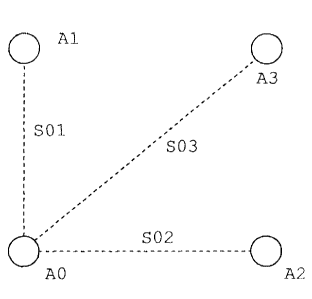
Fig. 2 shows the geometrical relationships between four
CA 02595296 2007-07-19
14
antennae A0, Al, A2 and A3 of an antenna array and the
base lines defined thereby. If the connecting line
between the antennae AO and Al is chosen as primary
base line S01, the connecting lines between the
antennae AO and A2 on the one hand and AO and A3 on the
other hand define the secondary base lines S02 and 503.
Fig. 3-5 explain successive limitation of the search
sector for permissible solutions.
Fig. 3 shows the still unrestricted search sector for
isolated solutions of the phase ambiguities. The
solutions are localized around an approximated position
for a solution of the pseudo-distance to the satellites
of a satellite-aided positioning system, the spacing of
the division of the sides of the sector being two
metres in each case. The crosses designate different
combinations for the phase ambiguity, which thus
represent candidates to be analyzed. In this example,
the search sector in fig. 3 comprises 4913 permissible
solutions.
Through a knowledge of the distance between two
antennae, a primary base line is defined and a
restriction is specified which, as a secondary
condition to be complied with, reduces the sector of
permissible solutions. After use of this information,
as shown in fig. 4, this still comprises 117 potential
candidates.
The introduction of a further restriction leads to the
limitation of the sector of permissible solutions,
which limitation is shown in fig. 5. By specifying the
CA 02595296 2007-07-19
maximum inclination relative to the horizontal, the
number of candidates in this example is reduced to 66.
In order to reduce this number even further, further
restrictions have to be added. One possibility is to
5 take into account further, secondary base lines.
A model according to the invention for calculating
these secondary base lines in association with the
primary base line is shown in fig. 6. The end points
10 of the primary base line S01 are fixed by the antennae
AO and Al, and the end points of the secondary base
line SOx are fixed by the antennae AO and Ax. From a
knowledge of the geometry of the antenna array, the
geometrical angle aolx between this primary base line
15 S01 and secondary base line SOx can be derived. There
remains as a degree of freedom the rotation of the
secondary base line SOx about the primary base line S01
acting as an axis, and hence a degree of rotational
freedom. This rotation is configured by the angle R.
The secondary base lines SOx are now calculated
according to the invention by varying the angle in
discrete steps, the antenna AO used equally for fixing
the two base lines forming a common point. By means of
this common point and a knowledge of the geometrical
angle aolx, the two base lines are related to one
another. For the secondary base lines SOx generated,
restrictions are once again derived, by means of which
solutions are eliminated so that the search sector is
further limited.
The embodiments shown represent only examples of
possible antenna arrays and are therefore not to be
understood as being definitive and limiting. Moreover,
-CA 02595296 2007-07-19
16
the person skilled in the art can derive further
antenna arrays suitable for a method according to the
invention, for example by arrangement in a plurality of
planes or in other geometrical forms. Furthermore, the
steps of the method can be combined or integrated so
that the sequence of limitations of the search sector
is effected in another way.