Note: Descriptions are shown in the official language in which they were submitted.
CA 02595442 2013-10-02
MF.Tucg.) OF BONE PLATE SI IA PlNci
10091f
BACKGROUND OF THE INVINTION
FIELD OF THF.. INVENTION,
109021 litis invention. relater; broadfy to surgical deviecs.
particularly, this
invention relates to orthopedic nnplants,, and specifically to elements to
implant and shape a
bone plate.
l'A'r I'. OF '1..1 I E A R-1',
1000,31 A li;Tinent and fixation or a fracture aro ivpicalk.- perfrolned by
ono of !,-everal
methods: casting,. external rixation, pinnitT, and plating. C'osiing is non-
invasive, but may
not be able to maintain alignment 01 (110 ft-0(qm,, where many bonc cragm(rnis
TherefOre.. as an alik.a.native, external lixators may be used. External
fixators Utiii4C7 ;I method
known as lic,amcntotaxis, which provides distraction t.i-aces across die joint
and permits the
Imeture to be aligned hased upon he tension placed on the surrounding
ligaments. However,
µvhile external rixators can maintain the position or the wrist bones. if may
nevertheless be
difficult in certain fractures to first: provide the bones in proper
alignment. In addition,
external rixators are often not suitable for fractures resultiiT in multiple
bone fragments.
Finniny with K-wires (Kirschner wires) is an invasive procedure whereby pins
arc positioned
into the various Crapments. 'Tins is a di Medi( and tune consuming procedure
thai provides
limited fixation the hone is comminuted or osteoporotie.
CA 02595442 2013-10-02
100041 Pim* uldizes a stabilizing metal plate typically placed
against thc.! hone.
FlxetkIngie 1:Steners (which may have threaded or non-threaded shafts)
positioned through
the plate and entering, drilled holes adjacent an articular bone surface, and
coil teal screws
eNktriding fi:oin the plate into holes drilled in the bone to provide
stabilized fracture fixation.
For example, co-owned 11.S. Pub, Na. 2004011)3164 Al to Orbay discloses a
plate
particularly adapted to treat dorsally displaced metaphyseal fractures from
the volar side or
the wrist
100051 When fiNed-angle fasteners are utilized in Conjunction
with a hone plate, it is
necessary to ensure that the pilot holes drilled for the. Losterters ore ca
axial with the hole
= axes. Otherwise, the shaft of the fasteners will not properly align with
the anatomy, and the
head of the fasteners will not properly align with the threaded holes of the
plate, potentially
resulitril.=.:iii eross-ihreading. As a result, with the plate placed upon the
bone, prior lo dntLhn
cacti tide in the hone in al il..11111e111. vithi it threaded hole, a drill
guide is attached to the plate
at the threaded hole. 'lime guide defines it tubular passage which directs the
drill bit in (he
proper orientation for a {timelier through the particular 1hre:uled hole.
Ariel-drilling each
hole, the drill etiide is removed. the fastener is inserted in the threaded
hole, and the drill
guide is coupled to a subsequent threaded hole.
100061 The process of -attaching the drill guide during the
surgical procedure is
CA 02595442 2007-07-24
laborious. It can be difficult to locate the appropriate angle for threadably
coupling the
guide to the peg hole during the procedure, given that each threaded hole may
have a
discrete axis angle from the other threaded holes. Such difficulty can
unnecessarily
prolong the surgical procedure.
[0003] Fragment plates are commonly used to fixate fractures along a bone,
e.g.,
along the diaphysis or at specific diaphyseal-metaphyseal or metaphyseal
locations. Such
plates are generally elongate, L-shaped, Y-shaped or have another shape which
is suited
for placement on a portion of a bone. The plates can be of varying length
depending
upon the intended fixation application. When fragment plates are provided with
threaded
holes they are subject to the same practical labor intensity for use as
presented above with
respect to the volar plate; i.e., it is laborious to attach a drill guide at
each threaded hole
for drilling a hole in alignment with the axis of the hole for receiving the
fixed angle
fastener therethrough.
[0004] In addition, the anatomy for which the fragment plates are
designed often
differs from the exact contours of the bone contacting surfaces of the plates.
Some
fragment plates have been designed to be shaped away from the bone for a
better
anatomical fit. However, presently available plating systems are not well
adapted for in
situ reconfiguration. Therefore, it has been necessary to shape a plate off
the target bone
with bending tools, remove the bending tools, place the plate in position on
the bone to
which the plate will eventually be attached, approximate the additional amount
of
reconfiguring required, remove the plate, and repeat the process until the
plate
approximately conforms to the shape of the bone. Moreover, in order to best
fit the
anatomy a plate may need to be re-contoured along three axes, and it has been
difficult to
3
CA 02595442 2007-07-24
transfer the contours of the anatomy to a stiff metal plate, especially when
such reshaping
is done at a distance from the bone.
[0005] Moreover, the problems with shaping a plate are compounded when
the
plate has threaded holes for receiving fasteners. In distinction from non-
fixed angle
fragment plates, inserting bending tools into the threaded holes of the plate
and applying
a force to the plate with the bending tools may distort the threads making
such holes
unaccepting to their threaded fasteners.
SUMMARY OF THE INVENTION
[0006] It is therefore an object of the invention to facilitate the
drilling of holes in
bone in alignment with the threaded holes in a bone plate.
[0007] It is another object of the invention to obviate the difficulties
presented in
connecting a drill guide in alignment with a threaded fixed angle hole in a
bone plate at
the time of surgery.
[0008] It is also an object of the invention to provide a system to
reshape a plate
while the plate is located on the bone.
[0009] It is a further object of the invention to provide a system which
permits
reshaping of the plate in three dimensions.
[0010] It is yet another object of the invention to provide a system
which protects
the threads of fixed angle holes during plate reshaping.
[0011] In accord with these objects, which will be discussed in detail
below, drill
4
CA 02595442 2007-07-24
guide tips are pre-assembled into at least one and preferably each of the
threaded holes of
the plate, so that the surgeon does not have to thread the drill guide with
the plate
positioned on the bone. The pre-assembly can be done by the operating room
technician
or at the factory. The drill guide tips may be reusable or disposable. The
tips are
sufficiently short that they do not interfere with adjacent tips or adjacent
structure on the
plate or intended to be inserted through the plate.
[0012] In a preferred method of pre-assembling the tips to the plate, a
nest of
short pins is placed beneath the plate such that the pins extend through the
holes in the
plate along the same angles as the axes of the holes. The pins then guide the
tips to be
threaded into the holes at the correct angle. Alternatively, no nest is
utilized and the tips
are individually guided into the holes at the appropriate angle. With respect
to a fragment
plate, such angle is typically normal to the bone contacting surface of the
plate.
[0013] There are two options for using the tips as drill guides. One is
to attach a
drill guide extension. The tip and extension together function as a
conventional drill
guide. After drilling, the extension is used to remove the tip from the plate.
According to
another use, the tip is used as a guide for a drill bit without any additional
extension and
then removed with a separate tool.
[0014] In addition, the guide tips have purpose other than for guiding a
drill. The
guide tips can also be used in conjunction with plate bending tools, and are
particularly
advantageous when the guide tips are pre-assembled on a fragment plate having
a
plurality of spaced apart fixed angle holes separated by a plate portion which
can be
deformed under force. Preferably two bending tools are used together to bend
the plate,
CA 02595442 2013-10-02
and the bending toiõils have first and second ends which are at least
partially inserted into
guide tips in two holes in the plate. Torque is applied by eouptin12, the
first ends of each of
the tools to the guide tips inserted in threaded holes and manipulating the
tools, lateral
bending forces (i.e.. heading within the plane of the plate) are applied with
the second ends in
the guide tips, and longitudinal bending forces are applied with the first
ends or a
combination of the first and second ends in the guide tips. The bending tools
can be operated
and force"; Can be applied to reshape the plate with the plate positioned
directly on the boric to
reshape the plate in close conformance to the bone surface. As the plate is
shaped at each set
of two holes, bending tools are removed and the guide tips can be used as
discussed above as
driIt guides to drill holes into bone beneath that portion of the plate. Fixed
angle screws are
then used to couple that portion of the fragnient plate to the hone. The
adjacent portion of the
plate is then shaped and fixed to the hone in a like manlier with the process
repeated until the
entire plate is shaped and coupled lo the hone.
1901.51 In another aspect, there is provided a method of shaping a bonc
plate.
comprising: a) providing a plate with holes and a plurality oldiserete tubular
guides coupled
within the holes: bl engaging at least one bending, tool at at least one of
the removable guides:
and c) manipulatinjt the at least one bending tool to bend the plate,
10015al In accordance with an aspect of the present invention, there is
provided the rise
of a hone plate for implanting on a hone, the use comprising the use of a
first portion of the
plate for a first coupling to the bone and the ilS6 of a second portion of the
plain. For a second
coupling to the bone, wherein the plate is for shaping between the first and
second couplings.
100i Sbl In accordance with another aspect of the present. invention, there
is provided
the use r at least one heading tool for elTagnir, at least one discrete
tubular removable guide
CA 02595442 2015-05-20
of a plurality of discrete tubular guides coupled within holes of a bone plate
for bending and
shaping the plate.
[0015c] In accordance with another aspect of the present invention, there
is provided a
use of a bone plate for implanting on a bone, the use comprising the use of a
first portion of
the plate for a first coupling to the bone and the use of a second portion of
the plate for a
second coupling to the bone, wherein the plate is for shaping between the
first and second
couplings for seating the plate closer to the bone before the second coupling.
[0016] Additional objects and advantages of the invention will become
apparent
to those skilled in the art upon reference to the detailed description taken
in conjunction with
the provided figures.
BRIEF DESCRIPTION OF THE DRAWINGS
[0017] FIG. 1 is a perspective view of a bone plate and a drill guide tip
being
6a
CA 02595442 2007-07-24
inserted or removed from the plate with a tool;
[0018] FIG. 2 is an exploded perspective view of drill guide tip and
tool;
[0019] FIG. 3 is a perspective view of the bone plate loaded with drill
guide tips
and K-wires;
[0020] FIG. 4 is a front end view of a head portion of the plate showing
that the
drill guide tips do not protrude through the bottom surface of the plate;
[0021] FIG. 5 is a perspective view of a drill guide tip and drill guide
extension;
[0022] FIG. 6 is a side elevation of a first embodiment of a drill guide
tip;
[0023] FIG. 7 is a top view of the first embodiment of the drill guide
tip;
[0024] FIG. 8 is a side elevation of a second embodiment of a drill guide
tip;
[0025] FIG. 9 is a side elevation view of an embodiment of a drill guide
extension;
[0026] FIG. 10 is a top view of a third embodiment of a drill guide tip;
[0027] FIG. 11 is a side elevation of a fourth embodiment of a drill
guide tip;
[0028] FIG. 12 is a bottom view of an embodiment of a drill guide
extension
engageable with the drill guide tip of FIG. 11;
[0029] FIG. 13 is an exploded side elevation view of a fragment plate
with guide
tips;
7
CA 02595442 2007-07-24
[0030] FIG. 14 is an exploded perspective view of the fragment plate and
guide
tips of FIG. 13;
[0031] FIG. 15 is a set of benders, shown in side elevation and
perspective view;
[0032] FIG. 16 is a top perspective view of the benders imparting a bend
along an
x-axis to impart a twist to the fragment plate along its longitudinal axis;
[0033] FIG. 17 is a perspective view of the benders imparting a bend
along a y-
axis to impart a lateral bend to the fragment plate;
[0034] FIG. 18 is an enlarged view similar to FIG. 17;
[0035] FIG. 19 is a side elevation view of the benders imparting a bend
along a z-
axis to impart a longitudinal bend to the fragment plate;
[0036] FIG. 20 is a perspective view of a fragment plate provided with
another
embodiment of a guide tip;
[0037] FIG. 21 is a top perspective view of the guide tip shown on the
plate in
FIG. 20;
[0038] FIG. 22 is a bottom perspective view of the guide tip shown on the
plate in
FIG. 20;
[0039] FIG. 23 is a side elevation of an assembly of FIG. 20 with another
embodiment of bender;
[0040] FIG. 24 is a broken bottom view of the assembly of FIG. 23;
8
CA 02595442 2007-07-24
[0041] FIG. 25 is a broken bottom perspective of the bender shown in FIG.
23;
[0042] FIG. 26 is a broken perspective view of the assembly of FIG. 23,
shown
applying a bend along the y-axis to a bone plate;
[0043] FIG. 27 is a broken bottom view showing the benders applying a bend
along the y-axis to the bone plate;
[0044] FIG. 28 is a top view of the plate with bend in the y-axis applied;
[0045] FIG. 29 is an end view of the plate, guide tip, and bender
assembly, with
the benders applying a bend along the x-axis to the bone plate;
[0046] FIG. 30 is a broken side elevation of the assembly of FIG. 29 in
which the
benders are applying a bend along the z-axis to the bone plate;
[0047] FIG. 31 shows a single bender applying a plate bend along the z-
axis;
[0048] FIG. 32 shows a single bender applying a plate bend along the y-
axis;
[0049] FIG. 33 is a broken side elevation of the assembly of the benders
being
used from the bottom of the plate to apply a bend along the z-axis to the bone
plate;
[0050] FIG. 34 is a side elevation of an assembly of another plate with
guide tips,
being bent along the x-axis by the benders;
[0051] FIG. 35 is a side elevation of the assembly of FIG. 34, in which
the plate
is further bent along the y-axis by the benders;
9
CA 02595442 2007-07-24
[0052] FIG. 36
is another plate according to the invention in the form of a volar
T-plate; and
[0053] FIG. 37 is another plate according to the invention in the form of
a
clavicle plate.
DETAILED DESCRIPTION
[0054] Turning
now to Fig. 1, a bone plate 10 is shown. The bone plate 10, and all
plates described herein, includes inner or lower (bone-facing) and outer or
upper (bone-
opposing) surfaces 10a, 10b. One or both of these surfaces may be contoured
generally
to follow a surface of a target bone (or bones) for which the bone plate is
intended, so
that the bone plate maintains a low profile and fits onto the bone(s). For
example, the
inner surface 10a of the plate may be generally complementary in contour to
the bone
surface. The outer surface 10b may correspond in contour to the bone surface
and may be
generally complementary to the inner surface of the plate.
[0055] Bone
plate 10 shown is particularly for placement over the volar side of the
distal radius. The bone plate 10 includes a plurality of threaded peg holes 12
for
threadably receiving the heads of pegs or locking screws (not shown) therein
and
relatively smaller alignment holes 14 sized to closely receive K-wires in a
fixed angle
orientation. In a preferred bone plate, the axes of the peg holes are all
oblique relative to
each other. In one of the peg holes, a drill guide tip 16 is shown being pre-
assembled into
the hole with an insertion tool 18. Referring to Figs. 1 and 2, in a preferred
embodiment,
CA 02595442 2007-07-24
the engagement between the insertion tool 18 and tip 16 is a tapered square 20
engaging a
circular opening 22, with the edges of the square driver providing sufficient
frictional
force to rotate the tip into and out of engagement with the plate 10. Other
suitable
engagements may be used as well.
[0056] Pre-assembly of the tips 16 into the peg holes of the plate 10 is
preferably
performed so that the surgeon does not have to thread the drill guide tips 16
with the plate
once the plate 10 is positioned on the bone during the procedure. The pre-
assembly can
be done by the operating room technician or at the factory. In a preferred
method of pre-
assembly, a nest of short pins 24 is placed beneath the plate such that the
pins extend
through the holes in the plate along the same angles as the axes of the holes.
The pins 24
then guide the tips to be threaded into the holes at the correct angle. With
respect to a
fragment plate, such angle is typically normal to the bone contacting surface
of the plate.
The pins 24 and insertion tool 18 are sized such that they do not interfere
with each other.
Alternatively, no nest is utilized and the tips 16 are individually guided
into the holes at
the appropriate angle. The drill guide tips 16 may be reusable or disposable.
[0057] Referring to Figs. 2 and 3, the tips 16 have a frustoconically
tapered upper
portion 30 and lower threaded portion 32, and are sufficiently short so that
they do not
interfere with adjacent tips, adjacent structure on the plate, or structure
intended to be
inserted through the plate, e.g., K-wires 50 through alignment holes 14.
Alternatively,
the upper portion 30 may be cylindrical. The lower threaded portion 32 of the
tips does
not have to be as long as conventional drill guides, as the threading into the
plate is done
away from the surgical environment under easier conditions, whether at the
factory (best
case) or pre-implantation at the medical facility. Shortening the threaded
portion reduces
11
CA 02595442 2007-07-24
protrusion of the guide tip below the plate relative to convention drill
guides, allowing
the plate 10 to sit closer to the bone while drilling, as discussed further
below.
[0058] The drill guide tips also eliminate the need to "countersink"
holes for a
drill guide for the distal row of holes in a distal radius plate. More
particularly and for
the following reasons, in the prior art it is initially necessary to drill
holes in bone through
the distal row of threaded peg holes with a drill bit larger than the diameter
of the peg
shaft which will eventually be inserted through the peg holes. The plate is
very thin at
the distal row. The prior art drill guide has a "nose" section which is
cylindrical and
unthreaded and approximately 0.030" long, which is slightly longer than the
pitch of the
peg-hole thread (0.023"). The nose section diameter is just under the inner
diameter of
thread so that it guides itself with one full turn of the thread and
establishes the direction
of the hole before the threads are engaged. If the plate thread depth is very
small (as is
the case for distal holes) there is no room below the plate for the nose
section of the drill
guide because the bone blocks entry. Thus, countersink holes must be drilled.
[0059] In accord with the invention, the drill guide tips do not require
a "nose"
section since they will be assembled with some other guidance (e.g., the above
described
nest of pins 24) or freehand. The drill guide tips can be made very short
since they need
just to hold on to the threads of the peg holes of a distal radius plate. One
and one-half
threads of engagement has been shown to provide a satisfactory coupling of the
tip to the
plate, and referring to Fig. 4 provides that the drill guide tip 16 does not
protrude through
the bottom 52 of the plate 10. In addition to eliminating the requirement for
countersinking, the fact that drill guide tips are so short results in the
plate seating almost
completely flush on the bone. Furthermore, the cylindrical unthreaded nose
portion of
12
CA 02595442 2007-07-24
the conventional drill guide, whose only job is to help the surgeon find by
feel the current
angle of the peg hole, is not required. A preferred size for each tip is
preferably
approximately 0.150 - 0.250 inch in length and certainly less than one inch.
As such, the
tip extends a short distance (maximum one inch and preferably not more than
0.25 inch)
above the upper surface (the surface opposite the bone contacting surface) of
the plate.
[0060] There are two options for using the tips as drill guides.
According to a
first option, the tips 16 are used as the sole guide for a drill bit and then
removed with a
tool similar to the insertion tool 18. The length of the tips provides
sufficient guidance
for the drill bit. In this use, the inner surface of the tip is preferably
hard, e.g., metal.
Thus, the tips 16 may be made entirely of metal or have an outer plastic body
with an
insert molded metal tube, e.g. hypotube, which is hard and readily available
with thin
walls.
[0061] Referring to Fig. 5 and according to a second option, a drill
guide
extension 34 may be attached to the top of the tip 16. The tip 16 and
extension 34
together function as a full length drill guide. The engagement between the
drill guide
extension 34 over the tip 16 is preferably such that a continuous constant
diameter path is
provided through the interiors of the extension and tip. To that end, the end
36 of the
extension 34 is preferably stepped to fit the upper portion of the tip. The
surgeon drills
through the drill guide extension and tip, thereby taking advantage of the
longer guidance
which may be used in conjunction with a scale and/or gauge to measure the
depth of the
drilled hole for peg length selection. After drilling, the extension 34 and
tip 16 are
removed from the plate 10, and the extension 34 may also function as a tool
for tip 16
removal. In fact, the taper at the upper portion 30 (Fig. 2) of the tip
provides a means for
13
CA 02595442 2007-07-24
axial and frictional engagement by the extension 34 which permits rotational
engagement. Once removed from the plate, the tip is then is pulled of the
extension by
hand or may be dispensed into a container without manual contact.
[0062] It is desirable to have some provision within the surgical set to
collect the
tips for counting as they are removed; i.e., to ensure that all tips from the
plate are
removed from the surgical site. In order to facilitate collection of the tips,
it is desirable
that the drill guide tips have a very conspicuous color, e.g., green or blue.
If made out of
metal, it may be desirable to make them out of titanium or aluminum and
anodize them in
a bright color that contrasts with the background in the surgical wound and
the bone
plate. A specialized container may be provided, or a dummy plate with threaded
holes
may be used to attach the tip thereto.
[0063] For drilling through the tips 16 where no drill guide extension is
used, it
may be desirable to modify the flutes of the drill bit, e.g. shortening and/or
increasing
twist, to reduce the play within the tip.
[0064] Other embodiments of the tips and extensions may be provided. For
example, referring to Figs. 6 and 7, the tips 116 may have an upper portion
130 with an
exterior hex shape, or any non-circular exterior cross-sectional shape that
will facilitate
torque transmission. To remove the tip from the plate the surgeon rotates the
extension,
unthreading the tip.
[0065] Turning now to Figs. 8 and 9, according to another embodiment of
the
invention, the tips 216 may be joined to the extension via one or more lateral
protrusions
240 on the body 230 of the tip and corresponding "key slots" 242 in the
extension 234.
14
CA 02595442 2007-07-24
[0066] Referring to Fig. 10, according to a further embodiment of the
invention,
the tips 316 may be joined to the extension by providing one or more corners
344 to the
inner circular opening 322 of the tip, and one or more outer corresponding
corners on the
extension which frictionally engage in the tip.
[0067] Turning to Figs. 11 and 12, according to another embodiment of the
invention, the tips 416 may include upper radially arranged slots 446 (e.g.,
180 or 120
separation) and the extension 434 includes corresponding radially arranged
pegs 448
which engage the tips 416 at the slots 446.
[0068] Turning to Figs. 13 and 14, the tips can also be used to
facilitate bending
of a fragment plate 500 in a manner that does not distort the threads at the
holes 502 at
which the tips 516 are coupled, as described below. The tips 516 are
cylindrical having
inside corners (similar to corners 344 in Fig. 10) to aid removal and/or
extension guide
coupling. Such distortion would otherwise prevent the holes 502 from accepting
fixed
angle fasteners with threaded heads which are later threadably coupled into
the threaded
holes.
[0069] Bendable plates, as described in more detail below, according to
the
invention may have at least one, and generally two or more, distinct anchor
(or bone-
attachment) portions including a threaded hole and at which the plate is
configured to be
secured to bone. Each anchor portion may be structured for a specific portion
of a bone,
generally to fit against a surface region of a specific or general bone. For
example, the
bone plate may include a proximal anchor portion for attachment to a more
proximal
region of a bone, and a distal anchor portion for attachment to a more distal
region of the
CA 02595442 2007-07-24
same bone. In some embodiments, the bone plates may include a support (or
buttress)
portion connected to an anchor portion. The support portion may lack
connective
features that permit a direct connection of the support portion to the bone
with one or
more fasteners. Such a support portion may limit movement of a bone fragment
using
contact between the support portion and the fragment, and may include
projections or
prongs to engage the fragment more effectively.
[0070] The bone plates described herein may be configured for use on any
suitable
bone of the human body and/or of another vertebrate species. Exemplary bones
may
include bones of the arms (radius, ulna, humerus), legs (femur, tibia, fibula,
patella),
hands, feet, the vertebrae, scapulas, pelvic bones, cranial and mandibular
bones, the ribs
and/or the clavicles, among others.
[0071] The fragment plate 500 is generally elongate, preferably designed
with a
series of alternating round anchor portions 504 and relatively narrower bridge
portions
506 that connect the anchor portions together. The anchor portions 504 have a
diameter
DA and a height HA, and the bridge portions 506 have a length LB, a width WB,
and height
HB. By way of example, and not by limitation, the following dimensions are
provided for
a plate for use on a radius bone: diameter DA = 0.22 inch, HA = 0.060 inch, LB
= 0.065
inch, WB = 0.085 inch, and HB= 0.50 inch. To maintain structural integrity and
desired
stiffness, while facilitating bendability, the length LB of each bridge
portion is preferably
less than one half, and more preferably less than forty percent, of the anchor
diameter DA.
The plate includes an inner (bone-facing) surface 512 and an outer (bone-
opposing)
surface 514. In use, a long axis Ap defined through the plate 500 may be
aligned with the
long axis of a corresponding bone or may extend obliquely or transversely
relative to the
16
CA 02595442 2007-07-24
long axis of the bone. The dimensions of the anchor and bridge portions 504,
506, and
the number of anchor and bridge portions, may be varied according to the
intended use,
for example, to match the plate with a preselected region of bone(s) and/or to
a particular
injury to the bone. The plates may be generally linear for use on the shaft of
a long bone
or may have a nonlinear shape, such as for use near an end of a bone. For
example, the
plate may be generally T-shaped, with a longer axis for attachment to a shaft
portion of a
bone, and a transverse portion connected to the longer axis portion, to
provide a wider
platform for attachment near an end of the bone. Also, by way of example, the
transverse
portion may be of a different construct, e.g., a plate portion without any
bridge portions
but multiple threaded holes, as shown in Fig. I. The plate may also be Y-
shaped. In
some embodiments, each bone plate may be configured for use on both sides of
the body,
such as when the bone plates are bilaterally symmetrical. In some embodiments,
each
bone plate may be asymmetrical and configured for use on either the left or
the right side
of the body.
[0072] Threaded holes 502 are provided in the anchor portions 504, and
preferably
each threaded hole 502 is provided with a guide tip 516. However, the tips may
be
strategically pre-assembled at locations that are recognized to commonly
benefit from
contour shaping for the plate 500 depending on the shape of the plate and to
best fit on
the bone.
[0073] Referring to Fig. 15, two preferably identical plate benders
(shaping tools)
550a, 550b have ends which can be coupled to the tips 516 and can be used
alone or
together to contour the plate 500 (Figs. 13 and 14). As described in more
detail below,
the benders 550a, 550b and tips 516 permit such plate contouring to occur with
the plate
17
CA 02595442 2007-07-24
500 positioned directly on the bone. Each tool, described with respect to tool
550a,
includes a handle portion 552a and first and second ends 554a, 556a which can
be at least
partially inserted into the guide tips 516. The first end 554a includes a
preferably axially
directed (or preferably at least directed generally parallel to the
longitudinal axis AL of
the handle portion 552a) peg element 558a which closely corresponds in size to
the inner
diameter of a guide tip 516. The second end 556a is provide with four peg
elements
560a, 562a, 564a, 566a, with two such pegs extending transversely to the
longitudinal
axis AL of the handle on each side 568a, 570a of the second end 556a. At one
such side
568a, the endmost peg element 560a closely corresponds in size to the inner
diameter of a
guide tip 516 and the inner peg element 562a has a stepped down nipple portion
572a,
whereas on the opposite side 570a of the second end the endmost peg element
564a has a
stepped down nipple portion 574a stepped down in diameter and the inner peg
element
566a closely corresponds in size to the interior of the guide tip 516. All the
peg elements
are preferably generally cylindrical, but may be polygonal or slightly
tapered.
[0074] As described as follows, the benders 550a, 550b can be coupled to
a
fragment plate at the guide tips 516 to apply torque, lateral and longitudinal
bending
forces to contour the plate; i.e., to bend the plate along x-, y- and z-axes.
In the present
embodiment it is preferred that the benders be coupled at adjacent guide tips
for localized
control of plate shaping. The plate is then shaped through a series of shaping
steps in
which adjacent portions of the plate are sequentially shaped, as needed.
Additionally all
such shaping, as also discussed further below, can be performed while the
plate is
positioned on the bone.
[0075] Referring to Fig. 16, in order to apply torque to the plate to
cause the plate
18
CA 02595442 2007-07-24
_
to twist, the peg elements 558a, 558b (Fig. 15) at the first ends 554a, 554b
of the benders
550a, 550b are inserted into preferably adjacent guide tips 516a, 516b. The
handle
portions 552a, 552b of the benders are then forced laterally relative to each
other so as to
apply a torque along the bridge portion 506 of the plate between the benders.
Such
torque results in defining a twist in the plate without deformation to the
threaded holes to
bend the plate along the x-axis.
[0076] Referring to Figs. 17 and 18, lateral bending forces
(i.e., bending within
the plane of the plate) are applied with the second end 556a, 556b of the
benders 550a,
550b coupled to the guide tips 516a, 516b, and then manipulating the benders
to bend the
plate about the y-axis. Referring to Fig. 18, more particularly, on bender
550a, peg
element 566a (see Fig. 15) is inserted into guide tip 516a and the nipple
portion 574a of
peg element 564a functions as fulcrum (rotational stop) against the bridge
portion 506a of
the plate to transfer rotational forces applied by the handle portion 552a of
bender 550a.
On bender 550b, peg element 560b (not shown, see Fig. 15) is inserted into
guide tip
516b and the nipple portion 572b of peg element 562b functions as a fulcrum
(rotational
stop) against the bridge portion 506b of the plate to transfer rotational
forces applied by
the handle portion 552b of bender 550b. As benders 550a, 550b are operated
together,
the resulting force subjects the plate to lateral bending at the bridge
portion 506a located
between the plate portions 504a, 504b at which the guide tips are coupled.
[0077] Referring to Fig. 19, longitudinal bending forces are
applied by inserting
the peg element at the first end 554a of bender 550a into guide tip 516c and a
peg
element, e.g. peg element 560b, at the first 554b or second ends 556b (shown)
of the
second bender 550b into the guide tip 516d. With the second end 556b coupled
at guide
19
CA 02595442 2007-07-24
_
tip 516d, the handle portion 552b thereof can be stabilized relative to the
bone. The
handle portion of tool 550a is then manipulated to bend the plate 500 at the
bridge portion
504 between the two benders to bend the plate relative to the z-axis.
[0078] It is also appreciated that a single bender can be used to
shape the plate once
at least a portion of the plate is fixed relative to the bone. Such is
described in more
detail below with reference to another embodiment of a bender.
[0079] Because the benders are not coupled at any locations below
the surface of the
plate nor do they have any portion which would otherwise interfere with the
bone or bone
contacting surface, plate shaping can occur directly on the bone. In one
method of
operation, a hole is first drilled through a guide tip at an end of the plate.
The guide tip is
then removed and a threaded fastener is inserted through the threaded hole of
the
fragment plate and into the drilled hole to couple the plate to the bone. The
benders are
then worked along the plate, moving hole by hole away from the first coupled
hole to
shape the plate to the bone as described above. As the plate is shaped at each
hole, if
needed, a hole is drilled through the respective guide tip, the guide tip is
removed and a
threaded fastener is inserted to hold the plate to the bone. One or both of
the benders are
then moved to subsequent holes along the plate for shaping until the plate is
fully
contoured and coupled to the bone. In another method, after the plate is
coupled to the
bone at an end, the plate is shaped along its entire length prior to coupling
to the bone at
remaining holes. In yet another embodiment, the plate may be shaped to the
bone before
it is attached at any screw hole. It is recognized that other variations on
shaping and
coupling can be used.
CA 02595442 2007-07-24
[0080] Turning now to Fig. 20, a shapeable bone plate 600 is shown with
another
embodiment of the guide tips 616. The plate is substantially as described
above with
respect to plate 500, including an alternating arrangement of anchor and
bridge portions
604, 606. Each anchor portion 604 is preferably curved along a constant radius
for at
least 1000 adjacent its adjacent bridge portion, and more preferably
approximately 120 ,
for cooperation with another embodiment of a plate bending tool 650a, 650b,
described
hereinafter.
[0081] Referring to Figs. 20 through 22, the guide tips 616 each have a
first end 618
assembled in a threaded hole in the anchor portion 604, a second end 620
extending
above an outer surface 614 of the anchor portion, and a circumferentially
extending
shoulder 622 disposed between the first and second ends, and preferably in
contact with
outer surface 614 of the plate 600. The shoulder 622 doubles the load carrying
capacity
of the guide tips 616 relative to the prior guide tips by reducing the load
carrying from
the thread/thread interface and transferring load carrying to the
shoulder/plate interface.
The second end 620 of the guide tip 616 preferably extends no more than 0.5
inch, and
more preferably is located not more than approximately 0.25 inch above the
outer surface
614 of the anchor portion.
[0082] Referring to Fig. 23, a pair of plate benders 650a, 650b is shown
coupled
to adjacent anchor portions 604a, 604b of the plate 600. The plate benders
650a, 650b
each include a first end 652a, 652b, a second end 654a, 654b, and a handle
656a, 656b
extending therebetween, with the respective handles 656a, 656b preferably
extending in
generally opposing directions. Referring to Figs. 23 through 25, the first end
652a
defines a socket 660a sized to closely receive a guide tip 616, and means for
rotationally
21
CA 02595442 2007-07-24
fixing the first end 652a relative to a portion of the bone plate 600, such as
the bridge
portion 606. In a preferred embodiment, the means for rotationally fixing the
first end
relative to the bone plate are two feet 662a, 664a that straddle the bridge
portion 606 of
the bone plate. The two feet 662a, 664a include curved inner surfaces 666a,
668a that
seat about the radiused portions 670, 672 of the anchor portion 604a to
quickly and easily
align the bender 656a on the plate. The feet 662a, 664a each have a toe end
674a, 676a
that abuts the bridge portion 606 at an optimal location to function as a
fulcrum for the
bender. Referring back to Fig. 23, the second ends 654a, 654b of the benders
define pegs
678a, 678b that are cylindrical and that step down in diameter from the
adjacent portion
of the handle. The handle 656a, 656b is preferably L-shaped and extends
between the
respective first and second ends. Each handle, e.g., 656a, includes a first
longitudinal
axis Al extending through its first end 652a and an adjacent portion of the
handle and a
second longitudinal axis A2 extending through the second end 654a and its
adjacent
portion of the handle. The handle 656a is preferably bent to offset the two
axes relative
to each other. Most preferably, the socket 660a at the first end 652a is
offset relative to
the second axis A2 by at least approximately 0.25 inch, more preferably at
least 0.5 inch
(to provide for guide tip and tissue clearance), but preferably by not more
than
approximately 3 inches (to maintain handle stability and control). It is noted
that the
benders 650a, 650b are preferably identical with the exception that the
handles are bent in
opposite directions from each other. The handles are coupled to the plate such
that the
longitudinal axis Al of each handle overlies the respective longitudinal axis
of the plate
portions surrounding the plate segment which is to be bent. An exception is
provided at
the anchor portion 604a at the end of the plate, where the appropriate bender
should be
22
CA 02595442 2007-07-24
coupled so that the handle extends outward from the plate, rather than over
the plate.
[0083] The plate 600 is generally bent so that its inner surface 612
thereof
approximates the shape of the bone surface generally in the manner described
above.
More particularly, referring to Figs. 26 and 27, a bend in the y-axis may be
imparted to
the plate at the bridge 606 between anchor portions 604a, 604b to which the
benders
650a, 650b are coupled by applying a relative rotational force. In imparting
such a bend,
the feet 662b, 664b of bender 650b stabilize anchor 604b, while the toe 674a
of foot 662a
functions as a fulcrum and the inner surface 668a of the opposite foot 664a
applies the
force to the anchor portion 604a to impart the desired bend. Without
relocating the
bender, force could be applied in an opposite rotational direction and the
opposite feet
would perform reverse functions. Each foot also functions as a stop to limit
angular
displacement to approximately 40 . The 'stop' function is effected in that the
toe end of
the foot operating as a fulcrum contacts the adjacent anchor portion after
approximately
40 of angular displacement and limits any further angular movement of the
anchor
portions relative to each other. Fig. 28 shows the plate 600 with a lateral
bend imparted
between anchor portions 604a and 604b after the benders have been removed from
the
plate.
[0084] In addition, the pegs 678a, 678b at the second ends of the benders
can be
inserted into the guide tips 616 at preferably adjacent anchor portions and
can be
manipulated to bend the plate relative to x- and z-axes; i.e., to impart
torque and a
resulting twist to the plate (x-axis displacement) and to longitudinally bend
the plate up
and/or down (z-axis displacement). Fig. 29 shows the benders 650a, 650b
imparting a
twist to the plate 600; i.e., to rotate anchor portion 604a in the x-axis
relative to anchor
23
CA 02595442 2007-07-24
portion 604b. It is appreciated that the benders may similarly be used to bend
the plate
along the z-axis.
[0085] However,
it is also recognized that the benders could possibly interfere
with each other when the necessary z-axis bend requires moving the benders
toward each
other in the same plane. Referring to Fig. 30, one way to overcome any
potential
interference is to move the benders 650a, 650b out of plane, but this may
impart an x-axis
twist to the plate 600, which could be undesired. Turning to Fig. 31, one
solution when
working in from the end of the plate (the ends of which are already fixed to
the bone 680
by screws 682) is to use a single bender 650a to impart a bend along the z-
axis.
Similarly, referring to Fig. 32, a bend along the x-axis can likewise be
imparted.
Referring to Fig. 33, another solution is to insert the pegs 678a, 678b (Fig.
23) of the
benders into the guide tips 616 from the bottom 612 of the plate and then
manipulate the
benders 650a, 650b away from each other to effect a bend about the z-axis
without any
bend about the x-axis. While it is recognized that the plate cannot be coupled
to the bone
during this type of bending, it nevertheless may be desirable to make certain
gross
contour adjustments with the plate located off the bone, e.g., prior to
applying the plate to
the bone.
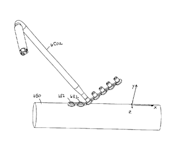
[0086] In most
instances, it is preferred that the bridge portion of the plate be
substantially narrower than the anchor portion to facilitate bending,
particularly a lateral
bend along the y-axis. Nevertheless, it is appreciated that plates with
smaller ratios of
anchor to bridge widths can also be bent and shaped using the guide tips and
tools
described herein, and there are circumstances where an overall relatively
stiffer plate may
be desirable. For example, referring to Figs. 34 and 35, a Y-shaped plate 700
with such a
24
CA 02595442 2007-07-24
smaller ratio is shown first being torqued along the x-axis to impart a twist
(Fig. 34) and
then being bent along the z-axis to impart a longitudinal bend (Fig. 35) in
accord with the
methods described above. In such a stiffer plate 700, it is preferable to
position the
benders 650a, 650b in guide tips that are spaced apart by at least one
threaded hole.
[00871 Also, while shapeable plates described above have a construct of
alternating anchor and bridge portions, it is recognized that hybrid plates
may be
provided that have both shapeable and relatively stiffer non-shapeable
portions. Such
plates are anticipated to be fracture specific and are rigid where the anatomy
is relatively
constant in contour across patients and shapeable where there may be
individual
variations in bone surface anatomy. For example, referring to Fig. 36, a volar
T-plate
800 is shown in which the axial shaft portion 802 is shapeable and provided
with guide
tips 816. In addition, the relatively transverse head portion 803 is
substantially non-
shapeable, with the exception of an anchor portion 804 coupled by a bridge 806
to the
remainder of the head portion 803. The anchor portion 804 is thus adapted to
be shaped
relative to the rest of the head portion to direct a fastener toward the volar
marginal
fragment. Preferably all the holes in the head portion are provided with guide
tips 817.
Guide tips 816 and 817 may be different sizes to accommodate relatively
different
diameter threaded holes in the respective portions of the plate. When the
guide tips are
removed from the head portion 803 and subchondral supports 818 (e.g., threaded
pegs or
screws) are inserted into the threaded holes therein, any load on the
subchondral supports
is transferred back to the axial shaft portion 802 of the plate 800. The same
principal can
be applied to other metaphyseal plates. By way of another example, a clavicle
plate 900
is shown in Fig. 37. The clavicle plate 900 has a relatively rigid non-
shapeable central
CA 02595442 2007-07-24
portion 902, and end portions 903 that are shapeable. The same principal can
be applied
to other diaphyseal places.
[0088] There
have been described and illustrated herein several embodiments of a
bone plate with pre-assembled guide tips, benders for use with a plate with
guide tips,
and methods of using the same. While particular embodiments of the invention
have
been described, it is not intended that the invention be limited thereto, as
it is intended
that the invention be as broad in scope as the art will allow and that the
specification be
read likewise. Thus, while the tips and benders have been shown with respect
to a volar
plate for dorsally displaced fractures and several fragment plates, it will be
appreciated
that the tips may be used in conjunction with threaded holes on other bone
plates as well.
For example, the tips may be used in conjunction with any plate for which they
would
provide advantage. In addition, one or more benders may be used to customize a
fracture
fixation plate for other bones, e.g., the clavicle, the ulna, the olecranon,
the jaw, the skull,
whether such plates are pre-formed flat or contoured to fit the anatomy.
Furthermore, a
distal radius plate having radial and ulnar sides provided with threaded fixed
angle holes,
the radial and/or ulnar sides being provided with guide tips and being
shapeable with the
benders, is considered within the scope of the invention. Also, a distal
radius plate
having shapeable segment(s) for capturing a volar marginal fragment is also
within the
scope of the invention. Optionally, such shapeable segment(s) may be removable
from
the plate if not used, e.g., by repeated bending, and provide a relatively
clean break with
the plate. In addition, while particular engagements between the tips and the
insertion/removal tool and the tips and drill guide extension have been
disclosed, it will
be understood that other suitable engagements, including non-destructive press-
fit, snap-
26
CA 02595442 2007-07-24
_
in, bayonet lock, etc. can also be used. Also, while the guide tips are
described as
threaded into the threaded holes, it is appreciated that non-threaded
assemblies, including
non-destructive press-fit, snap-in, bayonet lock, etc., which maintain the
tips in alignment
with the axes of the peg holes can also be used. While different benders have
been
shown, each can be used with multiple embodiments of the guide tips. With
respect to
the benders with multiple peg elements, preferred orientations of the peg
elements have
been described, but other configurations are possible within the scope of the
invention.
For example, the four peg elements can be located two each at, e.g., 90
apart. In
addition, such benders may only have two peg elements at a second end, each
with a
different configuration of larger and smaller size peg elements. Furthermore,
while it is
preferred to work a plate for shaping by coupling the benders at guide tips at
adjacent
holes, it is appreciated that not all holes of a shapeable plate need be
provided with a
guide tip and that the benders may be used relatively more spaced apart along
the plate
regardless of whether all holes of a shapeable plate include guide tips.
Moreover, while it
is preferable that the plate be coupled to be bone with bone screws while it
is shaped
relative to the bone, it is appreciated that the plate may be coupled to the
bone with
temporary fixation, such as with one or more clamps, during shaping.
Furthermore,
while the bendable plate segments are preferably bridge portions narrower than
the
surrounding anchor portions, it is appreciated that the one or more bendable
segments
may be of a different configuration than shown, provided that they are less
rigid than the
surrounding plate portions and are structured to deform prior to destruction
of the plate
threads in which the guide tips are threaded. It will therefore be appreciated
by those
skilled in the art that yet other modifications could be made to the provided
invention
27
,
CA 02595442 2007-07-24
without deviating from its scope.
28