Note: Descriptions are shown in the official language in which they were submitted.
CA 02595777 2007-07-24
WO 2006/086262 PCT/US2006/003992
-1-
ARTICLE HAVING A WEAR RESISTANT
COATING AND PROCESS FOR PRODUCING THE SAME
BACKGROUND OF THE INVENTION
[0001] The invention pertains to an article that has a wear-resistant coating
as
well as to a process for producing such article that has a wear-resistant
coating. More
specifically, the invention pertains to an article that comprises a substrate
and a wear-
resistant coating as well as to a process for producing such article that
comprises a
substrate and a wear-resistant coating.
[0002] In industrial processes, components of machinery and the like are often
times subjected to wear. The same is true for many other articles in that they
are often
times subjected to wear. It has proven to be beneficial to protect these
articles
(including components) from wear. A well-accepted way to provide such
protection
against wear of an article is to apply a wear-resistant coating thereto.
[0003] One common method of applying a wear-resistant coating is by a
thermal spray method. Thermal spray methods include processes that use
detonation
guns, high velocity oxygen flame spraying, plasma spraying, wire arc spraying,
and
flame spraying. There are, however, disadvantages associated with applying
coatings
via thermal spray methods. Except for vacuum plasma spraying, thermal spraying
exposes the powders being sprayed to oxygen or water vapor so as to result in
the
formation of metal oxides that can be detrimental to the coating. There is a
limitation
to the scope of the articles that are suitable for coating via thermal spray
methods
because there must a line of sight between the end of the spray nozzle and the
surface
to be coated. Further, if the angle of impingement of the spray on the
substrate is not
constant, it'is possible to deposit undesirable non-uniform coatings. U.S.
Patent No.
4,173,685 to Weatherly discloses the application of a wear and corrosion
resistant
coating to a substrate via a plasma or a d-gun technique.
[0004] Another process for applying wear-resistant coatings is described in
U.S. Patent No. 3,743,556 to Breton et al. The `556 Breton et al. patent
discloses a
process for applying a wear-resistant coating that first applies a cloth that
contains
particles of tungsten carbide to a surface that requires protection against
wear.
Second, another piece of cloth that contains particles of a braze alloy is
positioned
over the cloth that contains the carbide particles. The substrate with the two
layers of
CA 02595777 2007-07-24
WO 2006/086262 PCT/US2006/003992
-2-
cloth is placed in an inert-atmosphere furnace and then heated to the brazing
temperature of the braze alloy. The braze alloy infiltrates down into the
carbide
particles and brazes them to each other and to the substrate. Although this
process
produces a wear-resistant coating, this process has limitations with respect
to applying
a thin coating layer, as well as limitations as to the geometry of the
component since
the component must be accessed with fingers or tools. The cloth process also
can
sometimes present seams in the wear-resistant coating that can result in
structural
discontinuities in the carbide coating.
[00051 U.S. Patent No. 6,649,682 B1 to Breton et al. discloses a paint system
and process for hardfacing metal surfaces. In the `682 Brenton et al. Patent,
a paint
that includes a dispersion of hard particles is first applied as a coating to
the surface of
the substrate. Next, a paint including a dispersion of braze alloy is applied
over the
layer of hard particles. The substrate is then heated to cause the braze alloy
to melt
and infiltrate into the hard particles thereby bonding them to the metallic
surface. The
`682 Brenton et al. Patent also discloses an embodiment of the process wherein
a first
layer of adhesive is applied to the substrate and a hardfacing powder is then
applied to
the adhesive. A second layer of adhesive is applied and a braze alloy powder
is
applied to the second adhesive. The substrate is then heated whereby the braze
alloy
melts and infiltrates into the hard particles so as to bond them to the
metallic surface.
In a third embodiment of the `652 Brenton et al. Patent, a hardfacing alloy
powder
containing precipitated intermetallic hard compounds is made into a paint and
applied
to the surface that is to be protected. After drying, the paint is heated to
from a
coating. In a fourth embodiment, hardfacing particles and braze alloy powder
are
made into a paint and applied to the surface to be protected. The paint is
then dried
and heated to form the coating.
[00061 In a process such as that disclosed in `682 Breton et al. Patent, in
order
to obtain a layer of the paint that includes a dispersion of hard materials
that has
sufficient thickness, it takes multiple coats (or dips) of the substrate into
the paint to
achieve the necessary cladding thickness. At sharp corners or edges of the
substrate
the paint has a tendency to pull away which results in a thinner cladding and
a
premature wear in these areas adjacent to the sharp corners or edges of the
substrate.
CA 02595777 2010-09-17
68188-237
-3-
[0007] It would thus be desirable to provide a coating process, as well as an
article produced by the process, wherein the coating is not subject to
oxidation such as
is the case for coatings applied by thermal spray techniques.
[0008] It would thus be desirable to provide a coating process, as well as an
article produced by the process, wherein the coating can be applied in a
consistent
fashion to the substrate so as to result in a uniform coating
[0009] It would thus be desirable to provide a coating process, as well as an
article produced by the process, wherein the coating can be a relatively thin
coating.
[0010] It would thus be desirable to provide a coating process, as well as an
article produced by the process, wherein the coating can be applied to
components or
surfaces of components that are not accessible (or easily accessible) by hand
or tools.
[0011] It would thus be desirable to provide a coating process, as well as an
article produced by the process, wherein the wear-resistant coating is without
seams-
[0012] It would thus be desirable to provide a coating process, as well as an
article produced by the process, wherein it would not be necessary to use
multiple
coats or dips of a coating paint on a substrate to achieve the necessary
coating
(cladding) thickness.
[0013] It would also be highly desirable to provide a coating process, as well
as an article produced by such process, wherein the thickness of the coating
(or
cladding) is sufficient at sharp corners or edges of the substrate so as to
provide
adequate wear resistance in these areas.
[0014] It would also be highly desirable to provide a coating process, as well
as an article produced by such process, wherein the thickness of the coating
(or
cladding) at selected locations can be varied so that the substrate can have a
coating
that has a selectively variable thickness.
SUMMARY OF THE INVENTION
[00151 In one form thereof, the invention is an article produced by a process
that comprises the steps of. providing a substrate; applying a viscous coating
that
contains a ferromagnetic or paramagnetic component to at least a selected
portion of
the substrate; causing the selected portion of the substrate to be under the
influence of
CA 02595777 2007-07-24
WO 2006/086262 PCT/US2006/003992
-4-
a magnetic field; and transforming the viscous coating so as to form a wear-
resistant
coating on the substrate.
[0016] In another form thereof, the invention an article produced by a process
comprising the steps of: providing a substrate; contacting the substrate with
a viscous
coating wherein the viscous coating contains a ferromagnetic or paramagnetic
component; causing at least a portion of the viscous coating to be under the
influence
of a magnetic field; and transforming the viscous coating into a wear-
resistant coating
adhered to the substrate.
[0017] In still another form, the invention is an article produced by a
process
comprising the steps of: providing a magnetically permeable substrate; causing
at least
a selected portion of the substrate to be under the influence of a magnetic
field;
contacting the selected portion of the substrate with a viscous coating
wherein the
viscous coating contains hard particles and a braze material wherein the
viscous
coating contains a ferromagnetic or paramagnetic component; and transforming
the
viscous coating to a wear-resistant coating adhered to the substrate.
BRIEF DESCRIPTION OF THE DRAWINGS
[0018] The following is a brief description of the drawings that form a part
of
this patent application:
[0019] FIG. 1 is a mechanical schematic view of a first specific embodiment
for applying a coating to a substrate wherein a single magnet is attached to
the near
side surface of the substrate;
[0020] FIG. 1A is a mechanical schematic view of a second specific
embodiment for applying a coating to a substrate wherein a pair (i.e., a
plurality) of
magnets is attached to the near side surface of the substrate;
[0021] FIG. 1B is a mechanical schematic view of a third specific embodiment
for applying a coating to a substrate wherein an electro-magnetic field is
applied to the
substrate;
[0022] FIG. 2 is a colorized photomicrograph (with a scale of 150
micrometers) that shows the coating layer at a corner of the Control Sample
and the
photomicrograph shows the coating to have a thickness equal to about 135.1
micrometers;
CA 02595777 2007-07-24
WO 2006/086262 PCT/US2006/003992
-5-
[0023] FIG. 3 is a colorized photomicrograph (with a 150 micrometer scale)
that shows the coating layer at a side surface of the Control Sample and the
photomicrograph shows the coating to have a thickness equal to about 269
micrometers ;
[0024] FIG. 4 is a colorized photomicrograph (with a 150 micrometer scale)
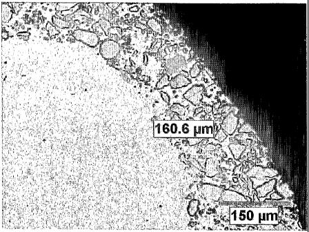
that shows the coating layer at a corner of a specific embodiment (Sample A)
wherein
the substrate was immersed in the viscous coating material with a magnet
applied to
one side surface (near side surface) of the substrate, but the magnet was
immediately
removed after the substrate was removed from the viscous coating material, and
the
photomicrograph shows the coating to have a thickness equal to about 160.6
micrometers;
[0025] FIG. 5 is a colorized photomicrograph (with a 150 micrometer scale)
that shows the coating on the opposite side surface of the substrate opposite
to the side
on which the magnet was attached for Sample A, and the photomicrograph shows
the
coating to have a thickness equal to about 282 micrometers;
[0026] FIG. 6 is a colorized photomicrograph (with a 150 micrometer scale)
that shows the coating on the near side surface of the substrate on which the
magnet
was attached for Sample A, and the photomicrograph shows the coating to have a
thickness equal to about 301.9 micrometers;
[0027] FIG. 7 is a colorized photomicrograph (with a 300 micrometer scale)
that shows the coating at a corner of the substrate of Sample B wherein the
substrate
was immersed in the viscous coating with a magnet applied to the substrate and
the
magnet was not removed from the substrate until after the coating had
solidified, and
the photomicrograph shows the coating to have a thickness equal to about 749.5
micrometers;
[0028] FIG. 8 is a colorized photomicrograph (with a 300 micrometer scale)
that shows the coating on the opposite side surface of the substrate opposite
from that
to which the magnet was applied for Sample B, and the photomicrograph shows
the
coating to have a thickness equal to about 410.4 micrometers; and
[0029] FIG. 9 is a colorized photomicrograph (with a 300 micrometer scale)
that shows the coating on the near side surface of the substrate to which the
magnet
CA 02595777 2007-07-24
WO 2006/086262 PCT/US2006/003992
-6-
was applied for Sample B, and the photomicrograph shows the coating to have a
thickness equal to about 617.5 micrometers.
DETAILED DESCRIPTION OF THE INVENTION
[0030] Referring to the drawings, FIG. 1 is a mechanical schematic view that
illustrates an arrangement for applying a coating to a substrate. In this
specific
embodiment, the substrate 20 should be a magnetically permeable material such
as,
for example, a ferromagnetic material or a paramagnetic material. Exemplary
suitable
substrates include: carbon and alloy steels, tool steels, martensitic and
ferritic stainless
steels. In this arrangement, the substrate 20 is illustrated as a generally
rectangular
planar geometry. It should be appreciated that the substrate can take on
virtually any
geometry so long as it can be immersed into the viscous coating material 26 or
the
viscous coating can be applied via other techniques. As discussed hereinafter,
the
substrate 20 can be a permanent magnet. The substrate can also comprise a non-
magnetic material. Thus, it can be seen that the present process has
application to a
wide variety of articles.
[0031] In this specific embodiment, the substrate 20 has a magnet 22 applied
thereto. Although the magnet is illustrated as generally cylindrical (or
circular), it
should be appreciated that magnets of different sizes and shapes can be
attached to (or
positioned adjacent to) the substrate 20. The attachment of the magnet 22 to
the
surface of the substrate 20 causes a magnetic field to be applied to at least
certain
portions of the substrate 20 (i.e., this portion of the substrate is under the
influence of
a magnetic field) and there is the possibility that a magnetic field may not
be applied
to other portions of the substrate which means that these other portions are
not under
the influence of a magnetic field. It should be appreciated that magnets may
be
positioned on the substrate so that a magnetic field is applied to the entire
substrate.
[0032] In this patent application, the use of the term magnetic field is
intended
to mean a magnetic field that is above the earth's ambient magnetic field.
[0033] The arrangement further includes a container 24 that contains a viscous
coating material 26 into which the substrate 20 is immersed (or dipped) so as
to apply
the coating 26 to the substrate 20. It should be appreciated that the viscous
coating
may be applied by other techniques such as, for example, painting. The viscous
CA 02595777 2007-07-24
WO 2006/086262 PCT/US2006/003992
-7-
coating material contains a ferromagnetic or paramagnetic component that is a
cemented hard particle. One preferred example of a suitable hard particle is
cobalt
cemented tungsten carbide particles. Other examples of suitable cemented hard
particles, in addition to cemented tungsten carbide, include one or more of
cemented
vanadium carbide, cemented niobium carbide, cemented chromium carbide,
cemented
titanium carbide and cemented tantalum carbide. The cemented hard particles
can
include any one or more of nickel, cobalt, iron and their alloys, as well as
copper-
based alloys or aluminum-based alloys.
[0034] In addition to the hard particles, the viscous coating material
contains a
braze material. The braze material can comprise the ferromagnetic or
paramagnetic
component of the viscous coating material. One exemplary braze material is a
nickel-
chromium-boron braze alloy. The viscous coating material can contain
additional
components (e.g., a polymeric agent) that assist in the flowability and
application of
the coating to the substrate. Additional descriptions of the hard particles,
the braze
material and other components of the viscous coating material are set out
hereinafter.
[0035] It should be appreciated that applicants contemplate that the
ferromagnetic or paramagnetic component of the viscous coating material can
comprise the hard particles and the braze material.
[0036] The substrate 20 is then removed from the container 24 and the coating
is allowed to dry and solidify. It is typical that the coating air dries. It
is also
contemplated that heat can be applied to the coating to assist in the drying
thereof. As
will become apparent from the discussion below, the magnet can either be
immediately removed from the substrate after the substrate has been removed
from the
viscous coating material or the magnet may remain on the substrate until the
coating
has dried, i.e., become solid.
[00371 Once the coating has dried, either with or without the application of
heat, the substrate with the dried coating thereon is heated to a temperature
above the
solidus of the braze material to effect the metallurgical bonding of the hard
particles to
the braze material. This heating step is the final step in the process that
solidifies (or
transforms) the viscous coating into a wear-resistant coating on the
substrate. As can
be appreciated the temperatures can vary depending upon the properties of the
braze
material, but exemplary temperatures range between a lower limit equal to
about
CA 02595777 2010-09-17
68188-237
-8-
875 C and an upper limit equal to about 1230 0C. It should also be
appreciated that
the heating process to effect the metallurgical bonding may include multiple
steps.
Exemplary heating processes to effect the metallurgical bonding are set forth
in U.S.
Patent No. 6,649,682 to Brenton et at.
(0038] FIG. IA is a mechanical view that illustrates a second specific
embodiment of an assembly by which one can apply the coating to a substrate
30.
This assembly includes a substrate 30 that has a pair of magnets (32, 33)
applied to the
rear surface thereof. It can be appreciated that a magnetic field can be
applied to more
than one portion of the substrate wherein magnets are located on only one side
surface. It is also contemplated that magnets can be positioned on both side
surfaces
of a substrate like substrate 30.
[0039] Like for the first arrangement, in order to apply the coating, the
substrate 30 is immersed (or dipped) into a container 34 that contains the
viscous
coating 36. The substrate 30 is then removed from the container 34 and the
coating is
allowed to dry and solidify. The magnets can either be immediately removed
from the
substrate after the substrate has been removed from the viscous coating
material or the
magnets may remain on the substrate until the coating has dried, i.e., become
solid.
[0040) In a specific embodiment in which one or more magnets are positioned
on the surface of the substrate, each magnet will cause at least a portion of
the
substrate to be under the influence of a magnetic field. Each magnet will not,
however, typically cause the entire substrate to be under the influence of the
magnetic
field which means that another portion of the substrate is not under the
influence of
the magnetic field. In such a situation, it can be expected that the thickness
of the
wear-resistant coating in the vicinity of the portion of the substrate under
the influence
of the magnetic field will be thicker than the thickness of the wear-resistant
coating in
the vicinity of those portion(s) of the substrate not under the influence of
the magnetic
field. It can thus be appreciated that the placement and the strength of the
magnets
produces a substrate with a wear-resistant coating wherein the wear-resistant
coating
can have a predetermined thickness at a selective location (i.e., a coating
with a
selectively variable thickness).
CA 02595777 2007-07-24
WO 2006/086262 PCT/US2006/003992
-9-
[0041] FIG. lB illustrates still another specific embodiment of the
arrangement to apply the viscous coating to the substrate. In this
arrangement, the
substrate 40 is subjected to an electro-magnetic field via electro-magnetic
apparatus
42 wherein an electric current-carrying wire 43 surrounds one portion of the
substrate
40. In order to apply the coating, the substrate 40 is immersed into a
container 44 that
contains the viscous coating 46. The substrate 40 is then removed from the
container
44 and the coating is allowed to dry and solidify. As will become apparent
from the
discussion below, the electro-magnetic field can either be immediately removed
from
the substrate after the substrate has been removed from the viscous coating
material or
the electro-magnetic field may be continuously applied to the substrate until
the
coating has dried, i.e., become solid. As another alternative, the electro-
magnetic field
can be increased during the solidification process. As still another
alternative, the
electro-magnetic field can be decreased (but not completely removed) during
the
solidification process.
[0042] In regard to the application of the magnetic field, applicant
contemplates that where the solidifying step comprises a drying step that
forms a dried
coating and a heating step that transforms the dried coating into the wear-
resistant
coating, the influence of the magnetic field can be changed after the applying
step and
prior to the drying step. More specifically, as one alternative, the influence
of the
magnetic field can be decreased after the applying step and prior to the
drying step.
As another alternative, the influence of the magnetic field can be removed
after the
applying step and prior to the drying step. As still another alternative, the
influence of
the magnetic field can be increased after the applying step and prior to the
drying step.
[0043] Applicants also contemplate that where the solidifying step comprises a
drying step that forms a dried coating and a heating step that transforms the
dried
coating into the wear-resistant coating, and the influence of the magnetic
field can be
maintained through the completion of the drying step.
[0044] Applicants also contemplate that an arrangement to apply the viscous
coating can have the magnetic field located about the substrate during all or
part of the
coating process. More specifically, the substrate does not itself have to be
magnetically permeable, but instead, a magnetic field is applied so as to be
about the
surface of the substrate (or in the vicinity of the surface of the substrate).
In this
CA 02595777 2010-09-17
68188-237
-10-
regard, a suitable substrate can be a titanium substrate or a titanium-based
substrate, as
well as a ceramic substrate.
[0045] Applicants further contemplate that the arrangement to apply the
viscous coating can have the magnetic field applied through the viscous
coating
material. li this regard, the substrate does not have to be magnetically
permeable, but
only that the magnetic field pass through the viscous coating during all or
part of the
coating process. For the arrangement in which the magnetic field passes
through the
viscous coating, a suitable substrate can be a titanium substrate or a
titanium-based
substrate, as well as a ceramic substrate.
[0046] Referring to the viscous coating material, the preferred hard particles
comprise cobalt cemented tungsten carbide particles. In regard to the
composition of
the cobalt cemented tungsten carbide particles, these particles comprise
between about
5.5 weight percent and about 6.8 weight percent cobalt and between about 93.2
weight
percent and about 94.5 weight percent tungsten carbide. Iii another
compositional
range, these particles comprise between about 5.5 weight percent and about
10.5
weight percent cobalt and between about 89.5 weight percent and about 94.5
weight
percent tungsten carbide. The tungsten carbide particles have a size that
ranges
between about 37 micrometers and about 53 micrometers.
[0047] The braze material can comprise any one or more of the following:
nickel, chromium, boron, silicon, iron, aluminum, gold, copper, manganese,
copper-
based alloys, aluminum-based alloys, other precious metals and alloys thereof.
A
preferred braze material is a nickel-chromium-boron braze alloy that has the
following
compositions: 4.0 wt.% B, 15.5 wt.% Cr and remainder Ni.
[0048] The viscous coating material further includes a polymeric agent. The
polymeric agent can be selected from the group comprising one or more of
crosslinked, acrylic emulsions. A preferred polymeric agent is an acrylate
polymer
that is sold by Rohm and Haas under the trade-mark Acrysol ASE-60.
[0049] A number of tests were run to evaluate the process of the present
invention. These tests are described along with the results hereinafter. For
all of the
tests set out below, the substrate comprised a one inch (2.54 centimeters) by
three inch
(7.62 centimeters) steel coupon having a thickness equal to about 0.250 inches
(6.35
millimeters). The substrate was made out of AISI 1018 steel. For all of the
tests, the
CA 02595777 2010-09-17
68188-237
-11-
viscous coating material comprised a water-based paint that contained cobalt
cemented tungsten carbide particles and a nickel-chromium-boron braze alloy
and an
acrylate polymer to hold the particles in suspension. The paint was
thixotropic. The
paint had a viscosity of 160,000 CP as measured with a Brookfield viscometer
rotating at 0.5 rotations per minute (according to ASTM Standard D2196) and
had a
density of about 5.0 grams per cubic centimeter as measured according to ASTM
Standard D 1475. The pH of the paint was neutral to slightly basic as measured
according to ASTM Standard E70.
[00501 The paint used in the tests was made according to the method as
outlined in U.S. Patent No. 6,649,682. More specifically, the following
components
TM
were mixed together: 1.890 milliliters (ml) of water, 42 grams of Surfynol 75
made
and sold by Air Products, Inc., 27 ml of a solution of 5% by weight of ammonia
in
water, 9630 grams of cemented tungsten carbide (6 weight percent cobalt and
the
balance tungsten carbide) with a mean grain size equal to 44 microns, and 8667
grams
of a nickel (balance)-chromium (15.5 weight percent)-boron (4.0 weight
percent)
eutectic braze alloy. Then 78 ml of Acrysol 60 thickening agent was titrated
into the
mixture as it was being stirred wherein the resulting viscosity was as set
forth above.
[0051) Tests were conducted to identify the differences between the coating
layer on the substrate due to the application of a magnetic field to the
substrate during
the immersion of the substrate in the viscous coating material and, as an
option,
during the drying of the coating on the substrate. More specifically, in one
test, i.e.,
Sample A, the magnetic field was applied to one side surface (i.e., the near
side
surface) of the substrate only during the immersion of the substrate in the
viscous
coating material, hi these tests the magnet was immediately removed after
removing
the substrate from the viscous coating material. In another test, i.e., Sample
B, the
magnet was applied to the near side surface of the substrate during the
immersion of
the substrate in the viscous coating material and was left on the substrate
until after
the coating had dried.
[00521 The testing included one Control Sample. The Control Sample did not
have a magnet attached thereto at any time during the immersion of the
substrate in
the viscous coating material or during the drying of the coating on the
substrate.
CA 02595777 2007-07-24
WO 2006/086262 PCT/US2006/003992
-12-
[0053] Referring now to the control test, the Control Sample was immersed
(or dipped) into the viscous coating material (i.e., the paint). A magnetic
field was not
applied to the substrate of the Control Sample. The control substrate was then
removed from the viscous coating material, and then allowed to dry at room
temperature for twenty-four hours.
[0054] In regard to the thickness of the coating layer on the Control Sample,
FIGS. 2 and 3 comprise photomicrographs that show the microstructure of the
coating
layer at two different locations on the substrate of the Control Sample. FIG.
2 shows
the coating layer at a corner of the substrate wherein the thickness of the
coating layer
at a corner of the substrate of the Control Sample is about 135.1 micrometers.
FIG. 3
shows the coating layer at one side surface of the substrate wherein the
thickness of
the coating layer on the side surface of the substrate of the Control Sample
is about
269 micrometers. The Control Sample represents what has been done in the past
in a
process in which the substrate is immersed in a viscous coating material,
removed
from the viscous coating material, and then allowed to air dry, and wherein a
magnetic
field is not applied to the substrate at any time during the entire coating
process.
[0055] In one (Sample A) specific embodiment of the process of the invention,
a magnet was attached to one side surface (or the near side surface) of the
substrate.
The substrate (with the magnet attached thereto) was immersed into the viscous
coating material. The substrate was removed from the viscous coating and the
magnet
was immediately removed from the substrate. The substrate was then allowed to
dry
at room temperature for twenty-four hours so as to form Sample A.
[0056] FIGS. 4-6 comprise photomicrographs that show the coating layer on
the substrate of Sample A at three different locations. FIG. 4 shows the
coating at a
corner of the substrate of Sample A wherein the thickness`of the coating is
about
160.6 micrometers. FIG. 5 shows the coating on the opposite side surface of
the
substrate (of Sample A) that was opposite to the near side surface on which
the
magnet was attached prior to removal. As shown in FIG. 5, the thickness of the
coating layer on the opposite side surface of the substrate of Sample A is
about 282
micrometers. FIG. 6 shows the coating layer on the near side surface of the
substrate
of Sample A where the magnet was originally attached prior to removal from the
CA 02595777 2007-07-24
WO 2006/086262 PCT/US2006/003992
-13-
substrate. As shown in FIG. 6, the thickness of the coating layer on the near
side
surface of the substrate of Sample A is about 301.9 micrometers.
[0057] In (Sample B) a second specific embodiment of the process of the
invention, a substrate that had a magnet attached to the near side surface
thereof was
immersed into the viscous coating material. The substrate was removed from the
viscous coating material and allowed to air dry at room temperature for twenty-
four
hours. The magnet remained attached to the substrate until the coating
material had
solidified.
[0058] FIGS. 7-9 show the coating layer at different locations, i.e., at one
corner, at the opposite side surface and at the near side surface, on the
substrate for
Sample B. As illustrated in FIG. 7, the coating layer at a corner of the
substrate of
Sample B has a thickness equal to about 749.5 micrometers. As illustrated in
FIG. 8,
the thickness of the coating layer on the opposite side surface of the
substrate that was
opposite to the side surface where the magnet was attached is equal to about
410.4
micrometers. FIG. 9 illustrates the coating layer on the near side surface of
the
substrate wherein a magnet was affixed during the complete process to produce
the
solidified coating. As illustrated in FIG. 9, the coating layer on the near
side surface
has a thickness equal to about 617.5 micrometers.
[0059] Table I below sets forth the thickness of the coating layer for the
Control Sample and Samples A and B at different locations on the substrate.
Table I
The Thickness of Coating Layers at a Corner,
the Near Side Surface and the Opposite Side Surface
Opposite Side Near Side Surface
Corner Surface Thickness Thickness of
Thickness of of Coating Coating
Sample Coating (micrometers) (micrometers)
(micrometers)
Control 135.1 269 269
A [magnet removed 160.6 282 301.9
after removal from
coating material]
B [magnet retained 749.5 410.4 617.5
until after coating
dried
CA 02595777 2007-07-24
WO 2006/086262 PCT/US2006/003992
-14-
As can be seen from the information set forth in Table I, it is very apparent
that the
application of a magnetic field to the substrate increased the thickness of
the coating
layer.
[0060] It is generally understood and accepted that for the geometry, i.e., a
solid rectangular geometry, of the substrates of the Control Sample and
Samples A
and B, the strength of a magnetic field applied to such a substrate is
strongest at the
corners of the substrate. For the substrates of the Control Sample and Samples
A and
B, it is also understood and well-accepted that the strength of a magnetic
field applied
to the substrate via a magnet attached to the near side surface, would be
stronger on
the near side surface to which the magnet is attached than on the opposite
side surface.
Keeping these principles in mind, the coating thickness data set forth in
Table I show
that an increase in the strength of the magnetic field applied to the surface
(or corners)
of the substrate results in an increase in the thickness of the coating layer
at that
location on the substrate.
[0061] Referring to the thickness of the coating layer at the corner of the
substrate (the location where the strength of the magnetic field would be
expected to
be the greatest), when the magnetic field was applied only during the
immersion of the
substrate in the viscous coating material, the coating thickness increased to
equal
about 118 percent of the coating thickness for the Control Sample. However,
when
the magnetic field was applied during the entire coating process (i.e.,
immersion and
drying), the coating thickness increased to equal about 555 percent of the
coating
thickness for the Control Sample.
[0062] Referring to the thickness of the coating layer on the opposite side
surface of the substrate (the location where the strength of the magnetic
field would be
the weakest), when the magnetic field was applied only during the immersion of
the
substrate in the viscous coating material, the coating thickness increased to
equal
about 104 percent of the coating thickness for the Control Sample. When the
magnetic field was applied during the entire coating process (i.e., immersion
and
drying), the coating thickness increased to equal about 152 percent of the
coating
thickness for the Control Sample.
[0063] Referring to the thickness of the coating layer on the near side
surface
of the substrate (the location where the strength of the magnetic field would
be
CA 02595777 2007-07-24
WO 2006/086262 PCT/US2006/003992
-15-
between the greatest and the weakest), when the magnetic field was applied
only
during the immersion of the substrate in the viscous coating material, the
coating
thickness increased to equal about 112 percent of the coating thickness for
the Control
Sample. However, when the magnetic field was applied during the entire coating
process (i.e., immersion and drying), the coating thickness increased to equal
about
230 percent of the coating thickness for the Control Sample.
[0064] A review of the above results shows that the application of a magnetic
field to the substrate can increase the coating (or cladding) thickness
multiple times
over a substrate on which there is no magnetic field. From a practical point
of view
what this means is that fewer immersions (or dips) of the substrate into the
viscous
coating material are needed to achieve a coating layer of a satisfactory
thickness.
This, in turn, means that fewer drying steps, which occur between each coating
step,
are necessary. Each one of these practical advantages leads to better
productivity in
the process of applying the coating to a substrate. Further, it is apparent
that the
application of a magnetic field increased the thickness of the coating layer
along the
corners (i.e., sharp edges) of the substrate so as to help with certain
applications,
especially those wherein the substrate has several edges or sharp corners.
[0065] It is thus apparent that the present invention provides a process, as
well
as an article produced by the process, wherein the coating is not subject to
oxidation
such as is the case for coatings applied by thermal spray techniques.
[0066] It is also apparent that the present invention provides a process, as
well
as an article produced by the process, wherein the coating can be applied in a
consistent fashion to the substrate so as to result in a uniform or controlled
variable
coating.
[0067] It is thus apparent that the present invention provides a process, as
well
as an article produced by the process, wherein the coating can be a relatively
thin
coating.
[0068] It is thus apparent that the present invention provides a process, as
well
as an article produced by the process, wherein the coating can be applied to
components or surfaces of components that are not accessible by hand or tools.
[0069] It is thus apparent that the present invention provides a process, as
well
as an article produced by the process, wherein the coating is without seams.
CA 02595777 2010-09-17
68188-237
-16-
[0070] It is thus apparent that the present invention provides a process, as
well
as an article produced by the process, wherein it would not be necessary to
use
multiple coats or dips of a coating paint on a substrate to achieve the
necessary
cladding thickness.
(00711 It is thus apparent that the present invention provides a process, as
well
as an article produced by such process, wherein the thickness of the cladding
is
sufficient at sharp corners or edges of the substrate so as to provide
adequate wear
resistance.
[0072] It is thus apparent that the present invention provides a coating
process,
as well as an article produced by such process, wherein the thickness of the
coating (or
cladding) at selected locations can be varied so that the substrate can have a
coating
that has a selectively variable thickness.
[0073] Other embodiments of the invention will be apparent to those skilled in
the art from a consideration of the specification or a practice of the
invention disclosed
herein. It is intended that the specification and examples are illustrative
only and are
not intended to be limiting on the scope of the invention. The true scope and
spirit of
the invention is indicated by the following claims.