Note: Descriptions are shown in the official language in which they were submitted.
CA 02596104 2015-04-08
CA2596104
METHOD FOR PRODUCING AND A SYSTEM FOR COOLING A
HOT-FILLED SOFTGEL CAPSULE
TECHNICAL FIELD
The present disclosure generally relates to softgel capsule manufacturing and,
more
particularly, relates to a method for producing and a system for cooling
softgel capsules formed by
encapsulating a hot fill material in a film followed by cooling the capsule
with a chilled liquid.
BACKGROUND
Soft capsules generally consist of a shell which is produced, for example, by
extending a
mixture of gelatin, plasticizer, and water into a thin sheet, film, or band.
Capsules formed from such
a sheet hold a wide variety of substances. The shell of a soft capsule is
typically produced, for
example, by adding, to an aqueous gelatin melt, a plasticizer in an amount of
30-40 wt % with
respect to the gelatin, and drying the shell until the water content becomes 5-
10% by weight.
One manufacturing process used to make soft capsules uses a rotary die machine
to
encapsulate a fill material between two films. The rotary die method is more
commonly referred to
as the Scherer process. In this process, for example, two separate, continuous
bands or sheets of
gelatin are feed into the rotary die machine. The fill material or ingredients
are simultaneously
injected by an injector wedge between the two gelatin bands as the bands are
drawn between two
opposing, rotating dies or rollers. The rotating dies each have a plurality of
cavities which align on
opposing sides of the gelatin bands. The bands are pinched between the dies
with each die cavity
essentially forming one-half of a capsule. Thus, the gelatin bands and the
fill material are
introduced between the rotating dies where the fill material is sealed within
the two halves of
gelatin. Once formed, the gelatin capsule is ejected from the rotating die
machine. Subsequent
processes are used to prepare the gelatin capsule for packaging and shipment.
As used in this disclosure and in the claims, the term gelatin is meant to
include not only the
mammalian gelatin such as bovine and porcine, but also fish gelatins and other
non- gelatin
materials that are useful in soft capsule preparation. Those skilled in the
art readily appreciate that
there are a number of non-gelatin materials that can be used for soft capsule
preparation such as
modified starches and carrageenans, modified starches alone, and other
compositions that are well
known to those skilled in the art.
- 1 -
CA 02596104 2015-04-08
= CA2596104
Gelatin is a substantially pure protein food ingredient, obtained by the
thermal denaturation
of collagen, which is the most common structural material and most common
protein in animals.
Gelatin forms thermally reversible gels with water, which gives gelatin
products unique properties,
such as reversible sol-gel transition states at near physiologic temperatures.
Therefore, gelatin
encapsulation of a fill material having an elevated temperature is
problematic.
The temperature influence on the gelatin's physical properties imposes
significant process
challenges for encapsulating fill materials that are heated prior to the
encapsulation process. This is
particularly true when the fill material approaches, or exceeds, a gelatin
sealing temperature.
Capsules having hot fill materials readily deform when they make contact with
external surfaces.
The deformation is due to the elevated temperature of the fill material which
maintains the gelatin at
a temperature where the gelatin is very soft and pliable. While deformation,
by itself, does not
generally result in any deleterious problems with how the capsule functions,
permanent deformation
is unacceptable from a product aesthetics perspective. That is, consumers
respond negatively to
poor shape uniformity, finding faceted or flattened capsules unacceptable.
Therefore, capsules that
are deformed or that lack of shape uniformity are not merchantable.
The soft capsule manufacturing industry has long sought a softgel
manufacturing processes
that can encapsulate hot fill materials within gelatin. The numerous
advantages of the gelatin
capsule may be expanded by enlarging the variety of fill materials that may be
encapsulated. In
addition, there is a need for a manufacturing process that is capable of
encapsulating hot fill
materials at a high rate, yet can provide aesthetically pleasing, uniformly
formed capsules which do
not permanently deform during subsequent handling or packaging. Finally, there
is a need for a
softgel manufacturing process that is environmentally friendly, consumer safe,
and cost effective.
The aforementioned qualities can be provided by contacting the capsule with a
chilled liquid
immediately subsequent to capsule formation.
SUMMARY
The present disclosure advances the state of the art with a variety of new
capabilities and
overcomes many of the shortcomings of prior devices in new and novel ways.
Subject matter
disclosed herein overcomes the shortcomings and limitations of the prior art
in any of a number of
generally effective configurations. The instant disclosure demonstrates such
capabilities and
overcomes many of the shortcomings of prior methods in new and novel ways.
- 2 -
CA 02596104 2015-04-08
CA2596104
A primary mixing system may be used to mix, homogenize, and heat one or more
fill
materials. The fill material may be pumped to a secondary mixing system which
heats the fill
material to a fill material temperature prior to being fed to an encapsulation
pump head assembly.
The encapsulation pump head assembly may receive the fill material from the
secondary mixing
system. A pair of rotating dies presses the fill material between the first
and second gelatin bands at
the gelatin bands sealing temperature, thus forming a capsule. In one
disclosed embodiment, the fill
material temperature is higher than the sealing temperature.
Following formation, the capsule is brought into contact with a chilled
liquid. The chilled
liquid may be at a chilled liquid temperature that is less than the fill
material temperature and the
sealing temperature. In one disclosed embodiment, the gelatin is cooled to a
handling temperature
so that it is sufficiently durable preventing discernible faceting or
flattening of the capsule during
further processing.
In another disclosed embodiment, the chilled liquid may be a liquid deemed
safe with respect
to product contact by the Food and Drug Administration. In one particular
embodiment, the chilled
liquid is fractionated coconut oil. Once the capsule is substantially at the
handling temperature, the
chilled liquid is separated from the capsule. Following separation of the
chilled liquid from the
capsule, the capsule is transferred into a dryer basket. The dryer basket
reduces the water content of
the capsule so that the gelatin sheath is not substantially sticky.
In another disclosed embodiment, the capsule may contact a flowing chilled
liquid layer. In
yet another disclosed embodiment, the flowing chilled liquid layer discharges
the capsule into a
chilled liquid bath.
The system for cooling a hot-filled softgel capsule is designed to cool the
capsule formed by
the rotary die machine. As previously mentioned, the rotary die machine
encases the fill material
between two gelatin bands by sealing the gelatin bands together at the sealing
temperature.
In one disclosed embodiment, a chilled liquid conveyor tray is filled with the
chilled liquid.
The chilled liquid conveyor tray is formed with a base, at least one sidewall,
a chilled liquid influent
port, and a discharge edge. The sidewall is connected to and surrounds a
portion of the base. Thus,
an interior surface and an exterior surface are formed. The chilled liquid
influent port extends from
the exterior surface to the interior surface to permit the chilled liquid to
flow into the chilled liquid
conveyor tray. The discharge edge connects the interior surface to the
exterior surface so that the
chilled liquid, carrying the capsule, may flow out of the chilled liquid
conveyor tray.
- 3 -
CA 02596104 2015-04-08
= CA2596104
The chilled liquid enters the chilled liquid conveyor tray through the chilled
liquid influent
port. The chilled liquid forms a flowing chilled liquid layer having a flowing
chilled liquid layer
depth and a liquid layer flow rate inside the chilled liquid conveyor tray.
The capsule drops into
contact with the flowing chilled liquid layer and heat flows from the capsule
to the chilled liquid.
The chilled liquid and the capsule flow across the discharge edge and out of
the chilled liquid
conveyor tray.
In another disclosed embodiment, the chilled liquid conveyor tray may include
a chilled
liquid layer forming base and the sidewall has a proximal side, a distal side,
and a back side. A
chilled liquid passageway is formed between the chilled liquid layer forming
base and the base. The
chilled liquid flows through a chilled liquid influent port into the chilled
liquid passageway, through
a chilled liquid layer forming passageway and onto a chilled liquid layer
forming surface.
In another disclosed embodiment, the system further includes a chilled liquid
tank filled with
the chilled liquid. The chilled liquid tank holds a chilled liquid bath with
flow of the chilled liquid
supplied from the chilled liquid conveyor tray. In another disclosed
embodiment, the system for
cooling a hot-filled softgel capsule may include discharging the capsules
directly into the chilled
liquid tank filled with the chilled liquid.
Thus, there is disclosed a method of producing a hot-filled softgel capsule
comprising the
steps: encapsulating a fill material at a fill material temperature by
injecting the fill material between
a first gelatin band and a second gelatin band wherein the first gelatin band
and the second gelatin
band are sealed at a sealing temperature such that a capsule is formed;
bringing the capsule into
contact with a chilled liquid wherein the liquid is at a temperature less than
the fill material
temperature, and wherein said chilled liquid is a Food and Drug Administration
approved liquid;
cooling the capsule with the chilled liquid to a handling temperature such
that the capsule does not
substantially deform, wherein the handling temperature is less than the fill
material temperature; and
separating the capsule from the chilled liquid, which comprises blowing a
pressurized gas onto the
capsule.
There is further disclosed a system for cooling a hot-filled softgel capsule
where a capsule is
formed by encasing a fill material held at a fill material temperature between
two gelatin bands
sealed together at a sealing temperature, comprising: a chilled liquid
conveyor tray formed with a
base, at least one sidewall, a chilled liquid influent port, and a discharge
edge, wherein the sidewall
is connected to and surrounds a portion of the base thereby forming an
interior surface and an
exterior surface, the chilled liquid influent port extends from the exterior
surface to the interior
- 4 -
CA 02596104 2015-04-08
CA2596104
surface, and the discharge edge connects the interior surface to the exterior
surface, wherein a
chilled liquid enters the chilled liquid conveyor tray at a chilled liquid
temperature through the
chilled liquid influent port and forms a flowing chilled liquid layer having a
flowing chilled liquid
layer depth and a liquid layer flow rate, whereby the capsule contacts the
flowing chilled liquid
layer, heat flows from the capsule to the chilled liquid, and the discharge
edge discharges the
capsule and the chilled liquid out of the chilled liquid conveyor tray.
Various objects and advantages of subject matter disclosed herein will become
apparent
from the following detailed description when viewed in conjunction with the
accompanying
drawings, which set forth certain embodiments.
Various embodiments of the claimed invention relate to a method of producing a
hot-filled
softgel capsule comprising the steps of: encapsulating a fill material at a
fill material temperature by
injecting the fill material between a first gelatin band and a second gelatin
band wherein the first
gelatin band and the second gelatin band are sealed at a sealing temperature
such that a capsule is
formed; bringing the capsule into contact with a flowing chilled liquid that
flows into a bath
containing the chilled liquid, wherein the chilled liquid is at a temperature
less than the fill material
temperature, such that heat is transferred from the capsule to the chilled
liquid and wherein the
capsule is transported to the bath and becomes immersed in the chilled liquid
in the bath; cooling the
capsule in the chilled liquid to a handling temperature such that the capsule
does not substantially
deform, wherein the handling temperature is less than the fill material
temperature; and blowing a
pressurized gas onto the cooled capsule to separate the capsule from the
chilled liquid in the bath.
Various embodiments of the claimed invention relate to a system for cooling a
hot-filled
softgel capsule where the capsule is formed by encasing a fill material held
at a fill material
temperature between two gelatin bands sealed together at a sealing
temperature, comprising: a
chilled liquid conveyor tray formed with a tray base, at least one sidewall, a
chilled liquid influent
port, and a discharge edge, wherein the sidewall is connected to and surrounds
a portion of the tray
base thereby forming an interior surface and an exterior surface, the chilled
liquid influent port
extends from the exterior surface to the interior surface, and the discharge
edge connects the interior
surface to the exterior surface, wherein a chilled liquid enters the chilled
liquid conveyor tray at a
chilled liquid temperature through the chilled liquid influent port and forms
a flowing chilled liquid
layer having a flowing chilled liquid layer depth and a liquid layer flow
rate, whereby the capsule
contacts the flowing chilled liquid layer, heat flows from the capsule to the
chilled liquid, and the
discharge edge discharges the capsule and the chilled liquid out of the
chilled liquid conveyor tray.
- 5 -
CA 02596104 2015-04-08
CA2596104
Such a system may further include a chilled liquid tank containing the chilled
liquid thereby creating
a chilled liquid bath, wherein: (A) the discharge edge is positioned relative
to the chilled liquid bath
so that the chilled fluid and the capsule flow from the chilled liquid
conveyor tray to the chilled
liquid tank; and (B) the chilled liquid tank has a capsule transfer conveyor
having a transfer
conveyor submerged portion, a transfer conveyor inclined portion, and a
transfer conveyor chilled
liquid removal portion wherein, (i) the transfer conveyor submerged portion
captures the capsule as
the capsule falls through the chilled liquid, (ii) the transfer conveyor
inclined portion transports the
capsule out of the chilled liquid bath, and (iii) the transfer conveyor
chilled liquid removal portion
has a chilled liquid removal device and a discharge end, wherein the chilled
liquid removal device
cleans a portion of the chilled liquid from the capsule and the capsule is
transported off the capsule
transfer conveyor at the capsule discharge end. Such a system may include: a
chilled liquid tank
filled with the chilled liquid thereby creating a chilled liquid bath at a
chilled liquid bath
temperature, wherein the capsule (i) drops into the chilled liquid bath, (ii)
sinks, and (iii) transfers
heat to the chilled liquid bath because the chilled liquid bath temperature is
less than the fill material
temperature, and the chilled liquid tank has a capsule transfer conveyor for
controlling the egress of
the capsule from the chilled liquid tank, wherein the capsule transfer
conveyor has a transfer
conveyor submerged portion, a transfer conveyor inclined portion, and a
transfer conveyor chilled
liquid removal portion, and wherein, (a) the transfer conveyor submerged
portion captures the
capsule as the capsule falls through the chilled liquid, (b) the transfer
conveyor inclined portion
transports the capsule out of the chilled liquid bath, and (c) the transfer
conveyor chilled liquid
removal portion has a chilled liquid removal device and a discharge end,
wherein the chilled liquid
removal device cleans a portion of the chilled liquid from the capsule and the
capsule is transported
off the capsule transfer conveyor.
BRIEF DESCRIPTION OF THE DRAWINGS
Without limiting the scope of the invention as claimed below and referring now
to the
drawings and figures:
FIG. 1 is a schematic of one embodiment, not to scale;
FIG. 2 is an embodiment of an encapsulation assembly, not to scale;
FIG. 3 is a schematic of an embodiment of the flowing chilled liquid layer and
an embodiment of
the chilled liquid bath showing capsules being transported with the flowing
chilled liquid layer to the
chilled liquid bath, not to scale;
- 6 -
CA 02596104 2015-04-08
= CA2596104
FIG. 4 is a perspective view of an embodiment of the chilled liquid conveyor
tray, not to scale;
and
FIG. 5 is a cross-sectional view taken along section line 5-5 in FIG. 4 of an
embodiment of the
chilled liquid conveyor tray.
DETAILED DESCRIPTION
Methods for producing and systems for cooling a hot-filled softgel capsule as
disclosed herein
enable a significant advance in the state of the art. The preferred
embodiments of the apparatus
accomplish this by new and novel arrangements of elements that are configured
in unique and novel
ways and which demonstrate previously unavailable but preferred and desirable
capabilities. The
detailed description set forth below in connection with the drawings is
intended merely as a description
of the presently preferred embodiments, and is not intended to represent the
only form in which the
subject matter described may be constructed or utilized. The description sets
forth the designs,
functions, means, and methods of implementation in connection with the
illustrated embodiments. It is
to be understood, however, that the same or equivalent functions and features
may be accomplished by
different embodiments that are also intended to be encompassed within the
scope of this disclosure and
the claimed invention.
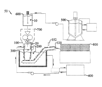
As seen in FIG. 1, the method for producing a hot-filled capsule may include a
primary mixing
system (500) used to mix and homogenize one or more fill materials (10).
During the mixing and
homogenization, the primary mixing system (500) heats the fill material (10)
to an elevated
temperature. For example, a heating bath may be coupled to a jacketed tank. A
heated fluid is
circulated from the heating bath to the tank to heat the fill material (10).
As one skilled in the art will
appreciate, the temperature may be controlled with a temperature sensing
device coupled to a
temperature controller which energizes a heat source.
With continued reference to FIG. 1, the fill material (10) is pumped to a
secondary mixing
system (600) which may, for example, be a transfer receiver. The secondary
mixing system (600)
may continue to perturb and heat the fill material (10) to a fill material
temperature prior to being
fed to an encapsulation pump head assembly (700). As one skilled in the art
will appreciate, other
means may be used to heat the fill material (10). Additionally, mixing the
fill material (10) while
heating may not be necessary. For example, the fill material (10) may be
locally heated, but not
mixed, immediately prior to entering the encapsulation pump head assembly
(700).
The encapsulation pump head assembly (700) is best seen in FIG. 2. In this
embodiment, the
encapsulation pump head assembly (700) may receive the fill material (10) from
the secondary
- 7 -
CA 02596104 2015-04-08
CA2596104
mixing system (600) together with a first gelatin band (14) and a second
gelatin band (16). A pair of
rotating dies encapsulates the fill material (10) between the first and second
gelatin bands (14, 16)
forming a capsule (20) where the fill material (10) is surrounded by gelatin.
As one skilled in the art
will observe and appreciate, encapsulating the fill material (10) between the
first and second gelatin
bands (14, 16) may require the gelatin to be held at a sealing temperature to
seal each half capsule to
the other in order to form the capsule (20). In one embodiment, the fill
material temperature is
approximately the same as the sealing temperature. In one particular
embodiment, the fill material
temperature is between approximately 38 degrees Celsius and approximately 45
degrees Celsius.
As the fill material temperature surpasses the sealing temperature, the
gelatin becomes progressively
softer, that is, the gelatin viscosity decreases, thus making uniform,
aesthetic capsule formation
more difficult. As one skilled in the art will observe and appreciate, gelatin
viscosity may be a
function of a number of factors, including the type of gelatin and the
temperature. For example,
pork, bovine, and fish gelatins do not exhibit the same viscosity relationship
with temperature.
With reference once again to FIG. 1, in this embodiment, once formed, the
capsule (20) is
brought into contact with a chilled liquid (200). The chilled liquid (200) is
at a chilled liquid
temperature. As one skilled in the art will observe and appreciate, when the
chilled liquid
temperature is less than the sealing temperature and the fill material
temperature, heat is transferred
from the capsule (20) to the chilled liquid (200) causing the temperature of
the capsule (20) to
decrease and the chilled liquid temperature to increase. In one embodiment,
the chilled liquid
temperature is between approximately minus 10 degrees Celsius and
approximately 10 degrees
Celsius. However, the chilled liquid temperature may be only slightly less
than the sealing
temperature or the chilled liquid temperature may be colder than minus 10
degrees Celsius. In either
case, any temperature difference between the chilled liquid (200) and the
capsule (20) that cools the
capsule (20) may be sufficient to prevent permanent deformation. For example,
as the temperature
difference between the fill material (10) and the chill liquid (200)
increases, the cooling rate of the
capsule (20) increases. Large capsules may require higher cooling rates to
bring them from the fill
material temperature to a handling temperature within a sufficient time period
to make their
manufacture cost effective. The chilled liquid temperature may be adjusted by
setting a target
temperature on a chilled liquid cooling system (400), best seen in FIG. 1.
Furthermore, by
maintaining the gelatin sheath at the handling temperature, the capsule (20)
may resist external
pressures exerted on the capsule (20). Thus, the capsule (20) is less likely
to form facets or flat
spots as a result of contact with external objects.
- 8 -
CA 02596104 2015-04-08
= CA2596104
In one embodiment, the chilled liquid (200) is a Food and Drug Administration
approved
non-aqueous liquid deemed safe for human consumption. In one particular
embodiment, the chilled
liquid (200) is fractionated coconut oil. Other representative non-aqueous
edible liquids suitable for
chilling include oils such as linseed oil, sesame oil, mustard oil, castor
oil, clove oil, and vegetable
and marine oils. In general, any material that does not degrade or dissolve
the soft capsule, is
relatively inexpensive, non-toxic, and easily removed from the soft capsule is
suitable for use herein.
Once the capsule (20) is substantially at the handling temperature, the
chilled liquid (200) is
separated from the capsule (20). In one embodiment, a large percentage of the
chilled liquid (200) is
removed from the capsule (20) with an air knife (352). The air knife (352)
forms a high pressure gas
stream and directs the gas stream onto the capsule (20). In one particular
embodiment, the gas
stream is between approximately 10 pounds per square inch (psi) and
approximately 60 psi. As seen
in FIG. 1, in another embodiment, following separation of the chilled liquid
(200) from the capsule
(20), the capsule (20) is transferred into a dryer basket (800). The dryer
basket (800) reduces the
water content of the capsule (20). As one skilled in the art will observe and
appreciate, numerous
drying baskets may be implemented, depending on the water volume desired, the
production rate,
and the capsule size, to name only a few factors. In one embodiment, for
example the embodiment
seen in FIG. 1, successful production of capsules of the size range #4 to #40
with any one or more of
the common shapes, such as round, oval, or oblong with heated fill materials,
is possible.
In another embodiment, as seen in FIGS. 3 and 5, the chilled liquid (200) may
take the form
of a flowing chilled liquid layer (170). The flowing chilled liquid layer
(170) is the chilled liquid
(200) formed into a flowing layer having a flowing liquid layer depth (172)
and a flowing liquid
layer flow rate. As one skilled in the art will observe, when the capsule (20)
contacts the flowing
chilled liquid layer- (170) heat is transferred from the capsule (20) to the
chilled liquid (200). In
addition, while cooling the capsule (20), the flowing chilled liquid layer
(170) transports the capsule
(20). In one particular embodiment, the flowing liquid layer depth is between
approximately 0.5
inches and approximately 2 inches. As the capsule size increases the flowing
liquid layer depth
(172) may also increase to help cushion the capsule (20) as it falls from the
encapsulation pump
head assembly (700) following formation. In another embodiment, the flowing
liquid layer flow
rate is between approximately 1 gallon per minute and approximately 30 gallons
per minute
depending on the flowing liquid layer depth (172) desired. Again, the capsule
size may determine
the liquid layer flow rate. As with the flowing liquid layer depth (172), one
skilled in the art will
- 9 -
CA 02596104 2015-04-08
CA2596104
appreciate that having a higher flowing, liquid layer flow rate will generally
provide a deeper
flowing liquid layer depth (172).
With reference to FIG. 3, in another embodiment, the flowing chilled liquid
layer (170)
discharges the capsule (20) into a chilled liquid bath (310) having a chilled
liquid bath depth (312).
Once the capsule (20) departs the flowing chilled liquid layer (170), the
capsule (20) may be
submerged in the chilled liquid bath (310) where heat is transferred from the
capsule (20) to the
chilled liquid bath (310). Similar to the flowing liquid layer depth (172),
the chilled liquid bath
depth (312) may increase, as the capsule size increases and as the fill
material temperature increases,
in order to provide sufficient cooling to the capsule (20) and to prevent the
capsule (20) from
deforming due to contact between the capsule (20) and another capsule or rigid
surface.
In another embodiment, immediately after the capsule (20) is formed by the
encapsulation
pump head assembly (700), the capsule (20) is brought into contact with the
chilled liquid bath
(310), as seen in FIGS. 1 and 3, held at a chilled liquid bath temperature.
The chilled liquid bath
temperature is less than the fill material temperature so that when the
capsule (20) contacts the
chilled liquid bath (310) heat is transferred from the capsule (20) to the
chilled liquid bath (310).
In one embodiment, a temperature drop from the fill material temperature to
the handling
temperature may be as little as 8 degrees Celsius for small capsules to bring
them to the handling
temperature. In another embodiment, the capsule (20) may require a temperature
drop of at least 34
degrees Celsius. The capsule size also influences the cooling period required.
Therefore, in one
embodiment, the cooling period may be between approximately 30 seconds and
approximately 120
seconds, depending on the capsule size, fill material temperature, capsule
production rate, and the
chilled liquid temperature. As one skilled in the art will appreciate, as the
capsule size increases, the
thermal mass of the fill material (10) increases relative to the mass of the
gelatin. In turn, as the fill
material thermal mass increases, the cooling period may increase in order to
remove additional
thermal energy to bring the capsule (20) to the handling temperature.
The system for cooling a hot-filled softgel capsule (50) may be designed to
cool the capsule
(20) formed by the rotary die machine. As previously mentioned and as seen in
FIG. 2, the rotary
die machine encases the fill material (10) between two gelatin bands by
sealing the gelatin bands
together at the sealing temperature.
As seen in FIGS. 4 and 5, in one embodiment, a chilled liquid conveyor tray
(100) is filled
with the chilled liquid (200). The chilled liquid conveyor tray (100) is
formed with a base (120), at
least one sidewall (110), a chilled liquid influent port (150), and a
discharge edge (160). The
- 10-
CA 02596104 2015-04-08
CA2596104
sidewall (110) is connected to and surrounds a portion of the base (120).
Thus, an interior surface
(130) and an exterior surface (140) are formed. The chilled liquid influent
port (150) extends from
the exterior surface (140) to the interior surface (130) to permit the chilled
liquid (200) to flow into
the chilled liquid conveyor tray (100). The discharge edge (160) connects the
interior surface (130)
to the exterior surface (140) so that the chilled liquid (200) may flow out of
the chilled liquid
conveyor tray (100). As one skilled in the art will observe and appreciate,
the chilled liquid
conveyor tray (100) may be designed to allow the chilled liquid (200) flow in
a laminar or turbulent
fashion. For example, various devices or structure may be added to the chilled
liquid conveyor tray
(100) to agitate the chilled liquid (200) thus creating a turbulent flow
pattern within the chilled
liquid conveyor tray (100). On the other hand, the dimensions of the chilled
liquid conveyor tray
(100) and the chilled liquid flow may be adjusted to provide laminar flow of
the chilled liquid (200)
within the chilled liquid conveyor tray (100). One skilled in the art will
also observe that the length
of the chilled liquid conveyor tray (100) may be designed to target a length
of time the capsule (20)
resides in the chilled liquid conveyor tray (100). Besides the length, the
declination of the chilled
liquid conveyor tray (100) may provide another means to control the length of
time the capsule (20)
spends in the chilled liquid conveyor tray (100).
During operation, as best seen in FIG. 5, the chilled liquid (200) enters the
chilled liquid
conveyor tray (100) through the chilled liquid influent port (150). The
chilled liquid (200) forms the
flowing chilled liquid layer (170) having the flowing chilled liquid layer
depth (172) and the liquid
layer flow rate inside the chilled liquid conveyor tray (100). Once formed,
the capsule (20) drops
into contact with the flowing chilled liquid layer (170). Heat flows from the
capsule (20) to the
chilled liquid (200) while the capsule (20) is transported to the discharge
edge (160). The chilled
liquid (200) and the capsule (20) flow across the discharge edge (160) and out
of the chilled liquid
conveyor tray (100).
As one skilled in the art will observe and appreciate, the chilled liquid
conveyor tray (100)
may have many configurations and accomplish cooling of the capsule (20)
subsequent to its
formation. For example, the chilled liquid influent port (150) may be located
in the sidewall (110)
rather than in the base (120). In another example, the discharge edge (160)
may be elevated from
the base (120) forming a shallow weir to aide in the formation of the flowing
chilled liquid layer
(170). In addition, the chilled liquid conveyor tray (100) may be formed from
a variety of materials.
By way of example and not limitation, the chilled liquid conveyor tray (100)
may be made of
stainless sheet metal or plastic.
- 11 -
CA 02596104 2015-04-08
CA2596104
In another embodiment, the chilled liquid conveyor tray (100) may be designed
to fit to an
existing rotary die machine. As seen in FIGS. 4 and 5, the chilled liquid
conveyor tray (100) may
include a chilled liquid layer forming base (180) and the sidewall (110) has a
proximal side (112), a
distal side (114), and a back side (116). The chilled liquid layer forming
base (180) extends from
the proximal side (112) to the distal side (114) of the sidewall (110). A
chilled liquid passageway
(190) is formed between the chilled liquid layer forming base (180) and the
base (120). The chilled
liquid layer forming base (180) has a chilled liquid layer forming surface
(182) and a chilled liquid
layer forming passageway (184). The chilled liquid passageway (190) provides
fluid
communication between the chilled liquid influent port (150) and the chilled
liquid layer forming
passageway (184), as best seen in FIG. 5. Thus, the chilled liquid (200) flows
through the chilled
liquid influent port (150) into the chilled liquid passageway (190). The
chilled liquid (200) then
flows through the chilled liquid layer forming passageway (184) and onto the
chilled liquid layer
forming surface (182) where the flowing chilled liquid layer (170) is formed.
In another embodiment, the system (50) further includes a chilled liquid tank
(300) filled
with the chilled liquid (200), as seen in FIG. 3. The chilled liquid tank
(300) holds a chilled liquid
bath (310) that is in fluid communication with the chilled liquid conveyor
tray (100) via the
discharge edge (160). During operation, the chilled fluid (200) and the
capsule (20) flow from the
chilled liquid conveyor tray (100) to the chilled liquid tank (300). The
chilled liquid tank (300) has a
capsule transfer conveyor (320) having a transfer conveyor submerged portion
(330), a transfer
conveyor inclined portion (340), and a transfer conveyor chilled liquid
removal portion (350).
The transfer conveyor submerged portion (330) captures the capsule (20) on a
capsule
capturing portion (332) as the capsule (20) falls through the chilled liquid
(200). The transfer
conveyor inclined portion (340) transports the capsule (20) out of the chilled
liquid bath (310) to the
transfer conveyor chilled liquid removal portion (350) where a portion of the
chilled liquid (200) is
removed. The transfer conveyor chilled liquid removal portion (350) may have
the air knife (352)
positioned to direct pressurized gas onto the capsules (20). The air knife
(352) cleans a portion of
the chilled liquid (200) from the capsule (20). The transfer conveyor chilled
liquid removal portion
(350) may have a discharge end (354). The capsule (20) is transported off the
capsule transfer
conveyor (320) at a capsule discharge end (354). As one skilled in the art
will observe and
appreciate, the transfer conveyor inclined portion (340) may be designed to
transport the capsules
(20) vertically out of the chilled liquid bath (310) rather than at along an
inclination, as seen in
FIGS. 1 and 3.
- 12 -
CA 02596104 2015-04-08
= CA2596104
As one skilled in the art will observe and appreciate, the cooling period may
be adjusted by
altering the depth of the chilled liquid bath (310) and the velocity of the
capsule transfer conveyor
(320). By increasing the depth of the chilled liquid bath (310) or by
decreasing the velocity of the
capsule transfer conveyor (320), the cooling period may be increased. As one
skilled in the art will
observe, even while the capsule (20) is in contact with the capsule transfer
conveyor (320), the
capsule (20) may not deform even though the fill material (10) may still be
hot. In addition to
providing a means for rapidly transferring heat from the capsule (20), when
the capsule (20) is
submerged in the chilled liquid (200), the chilled liquid (200) provides
buoyancy to the capsule (20).
Thus, the weight of the capsule (20) does not rest entirely on the capsule
contact area with transfer
conveyor (320) until the capsule (20) is removed from the chilled liquid (200)
at which point it has
been cooled to the handling temperature. The cooling period may require
adjustment depending
upon the capsule size, the fill material temperature, and the production rate.
In another embodiment, by redesigning the encapsulation pump head assembly
(700), the
system for cooling a hot-filled softgel capsule (50) may include discharging
the capsules (20)
directly into the chilled liquid tank (300) filled with the chilled liquid
(200). Similar to an
embodiment having both the chilled liquid conveyor tray (100) and the chilled
liquid tank (300), the
chilled liquid tank (300) may have the capsule transfer conveyor (320) having
the transfer conveyor
submerged portion (330), the transfer conveyor inclined portion (340), and the
transfer conveyor
chilled liquid removal portion (350).
In one embodiment, the liquid layer flow rate is between approximately 1
gallon per minute
and 30 gallons per minute. The liquid layer flow rate may be adjusted to
account for the
productivity of the encapsulation machine, the capsule size, the temperature
of the fill material, the
dimensions of the chilled liquid conveyor tray (100), and the chilled liquid
layer depth (172).
By way of example and not limitation, in one embodiment, a #40 capsule is
produced with
the fill material temperature of at least 38 degrees Celsius. After leaving
the encapsulation pump
head assembly (700), the capsule (20) drops into the liquid conveyor tray
(100). The chilled liquid
(200) is fractionated coconut oil held at a temperature of approximately 0
degrees Celsius. The
capsule (20) is cooled as the capsule (20) is transported across the discharge
edge (160) out of the
chilled liquid conveyor tray (100) and into the chilled liquid bath (310). The
capsule (20) sinks and
gently contacts the capsule transfer conveyor (320). The capsule transfer
conveyor (320) transports
the capsule (20) out of the chilled liquid (200) to the air knife (352) where
the majority of the chilled
liquid (200) is removed. The cooling period from the capsule (20) first
contact with the chilled
- 13 -
CA 02596104 2015-07-14
I"
liquid (200) to exiting the chilled liquid bath (310) is approximately 60
seconds. Moreover, no
permanent deformation is apparent in the #40 capsule.
In another example, the fill material temperature is greater than
approximately 35 degrees
Celsius. Following encapsulation where the gelatin is sealed around the fill
material (10), the
capsule (20) is dropped into the chilled liquid conveyor tray (100). The
chilled liquid
temperature is less than approximately 10 degrees Celsius. The capsule (20) is
transported into
the chilled liquid bath (310) and emerges between approximately 30 seconds and
60 seconds
later. In another example, the fill material temperature is at least
approximately 38 degrees
Celsius and the chilled liquid temperature is less than approximately 0
degrees Celsius.
Generally, as the fill material temperature increases, the chilled liquid
temperature decreases.
Numerous alterations, modifications, and variations of the preferred
embodiments
disclosed herein will be apparent to those skilled in the art and they are all
anticipated and
contemplated to be within the scope of the present disclosure and the claimed
invention. For
example, although specific embodiments have been described in detail, those
with skill in the
art will understand that the preceding embodiments and variations can be
modified to
incorporate various types of substitute and/or additional or alternative
materials, relative
arrangement of elements, and dimensional configurations.
INDUSTRIAL APPLICABILITY
The system for producing a hot-filled softgel capsule disclosed herein answers
a long
felt need for a system and method that is capable of encapsulating hot fill
material in gelatin.
The system is used to produce small or large softgel capsules of various
shapes by injecting the
heated fill material between two bands of gelatin introduced between two
rotating dies. The
present disclosure is of a system and method that implements a chilled liquid
subsequent to
encapsulation. The softgel capsules produced by the rotating dies contact the
chilled liquid
thus transferring heat from the capsule to the chilled liquid. The system and
method thereby
avoids some of the aesthetic problems associated with encapsulating hot fill
materials with
gelatin. The system produces softgel capsules that are safe for consumers, and
the system is
environmentally friendly and cost effective.
- 14 -