Language selection

Search

Patent 2596110 Summary

Third-party information liability

Some of the information on this Web page has been provided by external sources. The Government of Canada is not responsible for the accuracy, reliability or currency of the information supplied by external sources. Users wishing to rely upon this information should consult directly with the source of the information. Content provided by external sources is not subject to official languages, privacy and accessibility requirements.

Claims and Abstract availability

Any discrepancies in the text and image of the Claims and Abstract are due to differing posting times. Text of the Claims and Abstract are posted:

  • At the time the application is open to public inspection;
  • At the time of issue of the patent (grant).
(12) Patent: (11) CA 2596110
(54) English Title: SYSTEM FOR ASSEMBLING A HIGH-PRESSURE FLUID TUBE AND A FITTING ELEMENT, AND FITTING OBTAINED BY THIS SYSTEM
(54) French Title: SYSTEME D'ASSEMBLAGE D'UN TUBE A LIQUIDE SOUS HAUTE PRESSION ET D'UN ELEMENT D'AJUSTAGE, ET MONTAGE OBTENU
Status: Deemed expired
Bibliographic Data
(51) International Patent Classification (IPC):
  • F16L 13/11 (2006.01)
  • F16L 33/34 (2006.01)
(72) Inventors :
  • PICCINALI, EUGENIO (Italy)
(73) Owners :
  • MECCANICA FINNORD S.P.A. (Italy)
(71) Applicants :
  • MECCANICA FINNORD S.P.A. (Italy)
(74) Agent: ROBIC
(74) Associate agent:
(45) Issued: 2014-04-15
(22) Filed Date: 2007-08-03
(41) Open to Public Inspection: 2008-02-11
Examination requested: 2012-03-16
Availability of licence: N/A
(25) Language of filing: English

Patent Cooperation Treaty (PCT): No

(30) Application Priority Data:
Application No. Country/Territory Date
MI2006A 001621 Italy 2006-08-11

Abstracts

English Abstract


A system for assembling a high-pressure fluid tube on a tubular pin and which
is
provided to be used in particular on motorcycles and motor-vehicles, for
example
for the production of pipes intended for manufacturing braking circuits or
other
circuits, in which high-pressure oil or other fluids flow. in particular, the
high-pressure
fluid tube is of the kind comprising a first inner layer made of plastic, a
second layer made of a steel crossed mesh or other suitable material such as
fibers or the like, and a third coating layer, if any, made, for instance of
plastic
material. The system comprises a fitting element having a bush made of steel,
alloy or other material, wherein the high-pressure fluid tube is fitted on the

tubular pin and locked by crimping the metallic bush having a radial flange
extending into an annular groove of the tubular pin and distorting an 0-ring
gasket arranged in the annular groove between the radial flange and the
tubular
pin.


French Abstract

Système d'assemblage d'un tube de fluide à haute pression sur broche tubulaire et pouvant être utilisé sur des motocyclettes ou des véhicules motorisés, par exemple pour la production de tuyaux servant à la fabrication de circuits de freinage ou d'autres types de circuits dans lesquels circulent de l'huile à haute pression ou d'autres types de fluides. En particulier, le tube de fluide à haute pression comporte une première couche interne en plastique, une deuxième couche en maille croisée d'acier ou un autre type de matériau convenable comme des fibres ou un matériau semblable, et une troisième couche, s'il y a lieu, faite par exemple de plastique. Le système comprend un élément de raccord ayant une garniture en acier, en alliage ou un autre matériau. Le tube de fluide à haute pression est ajusté sur la broche tubulaire et bloqué par le pincement de la garniture métallique ayant une bride radiale s'étendant dans une rainure annulaire de la broche tubulaire et par la déformation d'un joint torique placé sur la rainure annulaire entre la bride radiale et la broche tubulaire.

Claims

Note: Claims are shown in the official language in which they were submitted.


5
WHAT IS CLAIMED IS:

1. System for assembling a high-pressure fluid tube on a tubular pin having
a
body, an annular groove adjacent to the body, and an extending portion
extending away from the annular groove, comprising:
a fitting element having a metal bush crimped over the tubular pin with a
radial flange of the fitting element extending into the annular groove of the
tubular pin and with the crimped bush of the fitting element extending over
the
extending portion of the tubular pin; and
an O-ring gasket arranged in said annular groove with said O-ring being
distorted and tightly fixed between the radial flange and the tubular pin by
the
crimping of the bush, for sealing the bush to the tubular pin;
the distortion of the O-ring gasket pressing the gasket against the walls of
said annular groove to create tightness between the radial flange and the
tubular
pin in the annular groove, and
the high-pressure fluid tube being arranged between the crimped bush
and the extending portion of the tubular pin.
2. System for assembling a high-pressure fluid tube according to claim 1,
wherein said bush is crimped so said bush distorts inwardly for engaging the
high-pressure fluid tube along the extending portion of the tubular pin and
for
penetrating into said groove, the high-pressure fluid tube having a plastic
layer
over the extending portion of the tubular pin, an intermediate layer for
resisting
high pressure over the plastic layer, and an external coating layer made of
rubber or plastic, over the intermediate layer and under the bush.

Description

Note: Descriptions are shown in the official language in which they were submitted.


CA 02596110 2007-08-03
SYSTEM FOR ASSEMBLING A HIGH-PRESSURE FLUID TUBE AND A
FITTING ELEMENT, AND FITTING OBTAINED BY THIS SYSTEM.
The present invention refers to a system for assembling a high-pressure
fluid tube on a tubular pin, which is part of a fitting element provided to be
used in particular on motorcycles and motor-vehicles, for example for the
production of pipes intended for manufacturing braking circuits or other
circuits, in which high-pressure oil or other fluids flow.
In particular, the invention relates to a system for assembling a high-
In order to avoid any oil leakage, which nfay occur in the vehicle systems
made by the known methods, the invention teaches to create, in the pin
where the tube is fitted into, an annular groove assigned to lodge an OR-
type gasket.
The system for assembling according to the invention enables to create,
without the use of particularly complex and expensive equipment or

CA 02596110 2007-08-03
tightness and, as a result of it, are able to pass the strict tests provided
for
by the regulations on this subject.
As it is known, most of vehicles equipped, provided with circuits that bring
fluids under pressure, comprise also parts made of hoses, provided at the
ends with fittings elements to be coupled with corresponding elements
fitted on the vehicle.
The said hoses comprise, in general, three of more layers: an inner layer
made of plastic, an intermediate layer consisting of a steel plait able to
resist internal high pressure, and a third layer, a coating layer, made of
plastic.
At the ends, on the said hoses, metal bushes are fitted into, generally
made of steel, which are then locked by crimping or caulking, to lock the
hose on the pin.
On the other hand, it often happens that due to the high pressure, the fluid
IS circulating in the hose, even if in a small amount, seeps between the
hose
internal and external wall of the pin, thus affecting, over the time, the
correct operation of the system, with the risk of creating hazardous
situations.
The sector feels therefore the need to be provided with means capable of
assembling a high-pressure fluid tube on a pin, which is a part of a fitting,
thus guaranteeing the system to be perfectly sealed.
This system is now solved by this invention, which refers to system for
assembling a high-pressure fluid tube, provided, in the pin body, with an
annular seating, wherein an OR-type gasket is fitted.
In this seating, one end of the said metal or alloy bush is inserted, which

CA 02596110 2013-10-17
3
distorts during the crimping and pushes and distorts the gasket, by
pressing it against the walls of the seating and thus guaranteeing a total
tightness.
More particularly, the present invention provides a system for assembling a
high-
pressure fluid tube on a tubular pin having a body, an annular groove adjacent
to
the body, and an extending portion extending away from the annular groove,
corn prisi ng:
a fitting element having a metal bush crimped over the tubular pin with a
radial flange of the fitting element extending into the annular groove of the
tubular pin and with the crimped bush of the fitting element extending over
the
extending portion of the tubular pin; and
an 0-ring gasket arranged in said annular groove with said 0-ring being
distorted and tightly fixed between the radial flange and the tubular pin by
the
crimping of the bush, for sealing the bush to the tubular pin;
the distortion of the 0-ring gasket pressing the gasket against the walls of
said annular groove to create tightness between the radial flange and the
tubular
pin in the annular groove, and
the high-pressure fluid tube being arranged between the crimped bush
and the extending portion of the tubular pin.
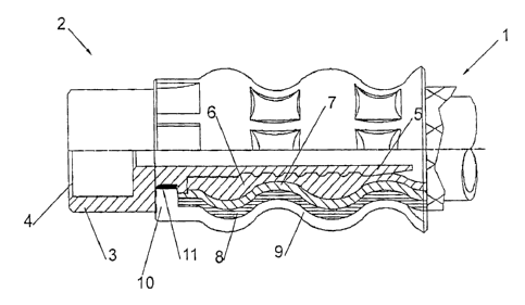
This invention will be now described in detail, by way of example but
without any limitation thereto, with reference to the drawing annexed
hereto, which shows, in section, the end of a high-pressure tube fitted on a
fitting element according to the invention.
With reference to the drawing, reference number 1 indicates, as a whole,
the end of a high-pressure tube, fitted on a fitting element indicated, as a
whole, with reference number 2.

CA 02596110 2013-10-17
3a
This fitting element is substantially composed of a body 3, which is
provided with a thread 4 or, however, known means suitable to allow the
seal thereof with a complementary fitting element fitted on the vehicle, and
a pin 5 on which the end of the tube 1 is fitted,
The latter consists of an inner layer 6 made of plastic, such as, in
particular, PTFE or also other plastic material, for example PA12 or PA11
or the like, one intermediate layer 7 consisting of a steel crossed mesh or
of textile material such as Gore-Tex, in carbon fibre, or in other material
capable of resisting the high-pressures of fluid circulating inside the tube,
and, if necessary, a third external coating layer 8, made of rubber or
plastic, for example PA.
A bush made of suitable metal, which can be steel, brass, an alloy or
otherwise, indicated with reference number 9, is fitted on the end wall of
the tube. The said bush is distorted by caulking or crimping, in such a way
as to tighten lock it around the said tube. _______________________

CA 02596110 2013-10-17
4
The invention is characterised in that it provides, in the fitting element 2,
for an
annular groove 10, in which a gasket 11 is lodged, preferably an OR-ring
gasket.
During the caulking operation, the edge of the metal or alloy bush 9 is bended

and pushed inside the annular groove 10, thus exerting pressure on gasket 11,
which distorts and is then heavily pressed against the groove walls, thus
creating
a perfect seal.
As it can be clear from the description above, the tube according to the
invention
requires an extremely inexpensive production method, since it permits to use
the
same equipment and the same components used until now for fittings of the
known art, without the need of particular investments.
The dimensions, as well as the materials used, may vary according to the needs

of use.

Representative Drawing
A single figure which represents the drawing illustrating the invention.
Administrative Status

For a clearer understanding of the status of the application/patent presented on this page, the site Disclaimer , as well as the definitions for Patent , Administrative Status , Maintenance Fee  and Payment History  should be consulted.

Administrative Status

Title Date
Forecasted Issue Date 2014-04-15
(22) Filed 2007-08-03
(41) Open to Public Inspection 2008-02-11
Examination Requested 2012-03-16
(45) Issued 2014-04-15
Deemed Expired 2020-08-31

Abandonment History

There is no abandonment history.

Payment History

Fee Type Anniversary Year Due Date Amount Paid Paid Date
Registration of a document - section 124 $100.00 2007-08-03
Application Fee $400.00 2007-08-03
Expired 2019 - The completion of the application $200.00 2008-10-20
Maintenance Fee - Application - New Act 2 2009-08-03 $100.00 2009-07-09
Maintenance Fee - Application - New Act 3 2010-08-03 $100.00 2010-06-28
Maintenance Fee - Application - New Act 4 2011-08-03 $100.00 2011-06-14
Request for Examination $800.00 2012-03-16
Maintenance Fee - Application - New Act 5 2012-08-03 $200.00 2012-05-16
Maintenance Fee - Application - New Act 6 2013-08-05 $200.00 2013-05-24
Final Fee $300.00 2014-01-30
Maintenance Fee - Patent - New Act 7 2014-08-04 $200.00 2014-05-12
Maintenance Fee - Patent - New Act 8 2015-08-03 $200.00 2015-04-10
Maintenance Fee - Patent - New Act 9 2016-08-03 $200.00 2016-06-01
Maintenance Fee - Patent - New Act 10 2017-08-03 $250.00 2017-05-24
Maintenance Fee - Patent - New Act 11 2018-08-03 $250.00 2018-05-07
Maintenance Fee - Patent - New Act 12 2019-08-06 $250.00 2019-07-04
Owners on Record

Note: Records showing the ownership history in alphabetical order.

Current Owners on Record
MECCANICA FINNORD S.P.A.
Past Owners on Record
PICCINALI, EUGENIO
Past Owners that do not appear in the "Owners on Record" listing will appear in other documentation within the application.
Documents

To view selected files, please enter reCAPTCHA code :


To view images, click a link in the Document Description column. To download the documents, select one or more checkboxes in the first column and then click the "Download Selected in PDF format (Zip Archive)" or the "Download Selected as Single PDF" button.

List of published and non-published patent-specific documents on the CPD .

If you have any difficulty accessing content, you can call the Client Service Centre at 1-866-997-1936 or send them an e-mail at CIPO Client Service Centre.


Document
Description 
Date
(yyyy-mm-dd) 
Number of pages   Size of Image (KB) 
Office Letter 2021-11-25 1 190
Abstract 2007-08-03 1 20
Description 2007-08-03 4 126
Claims 2007-08-03 1 35
Drawings 2007-08-03 1 13
Representative Drawing 2008-02-07 1 12
Cover Page 2008-02-08 2 48
Claims 2013-10-17 1 35
Abstract 2013-10-17 1 22
Description 2013-10-17 5 152
Cover Page 2014-03-17 1 47
Assignment 2007-08-03 5 127
Correspondence 2008-04-18 2 55
Correspondence 2008-10-20 1 50
Correspondence 2009-10-01 1 27
Fees 2009-07-09 1 54
Fees 2010-06-28 1 53
Correspondence 2010-08-10 1 44
Fees 2011-06-14 1 55
Correspondence 2012-03-29 1 81
Prosecution-Amendment 2012-03-16 2 60
Fees 2012-05-16 1 54
Prosecution-Amendment 2013-04-30 3 100
Fees 2013-05-24 1 55
Prosecution-Amendment 2013-10-17 16 490
Correspondence 2014-01-30 2 59
Fees 2014-05-12 1 39
Fees 2015-04-10 1 39