Note: Descriptions are shown in the official language in which they were submitted.
CA 02596268 2007-07-27
WO 2006/081488 PCT/US2006/003072
ROTATIONAL APPARATUS
RELATED APPLICATIONS
This application claims the benefit of U.S. Provisional Application No.
60/593,608 filed January 28, 2005, and entitled Rim-Driven Fluid Pump System,
and
U.S. Patent Application No. 11/293982 filed December 5, 2005, and entitled
Rotational
Apparatus, the entire contents of which are incorporated herein by reference.
BACKGROUND OF INVENTION
The present invention relates to a rotatable element, and more particularly,
to a
non-axle driven apparatus having a magnetic bearing and drive means.
One conventional technique to drive a rotation element such as an impeller of
a
rotational apparatus is through the use of an impeller drive shaft. The
impeller drive
shaft often penetrates a housing and the driven fluid to connect to a center
hub of the
impeller. Such a configuration causes the impeller drive shaft to travel
through the
pump housing and the driven fluid, thus, requiring features such as fluid
seals or shaft
housings to seal the shaft as it penetrates the housing to prevent the driven
fluid from
exiting the housing or through the point of shaft entry.
Recent improvements in rotational apparatus technology have eliminated the
need for the drive shaft to drive to an impeller of a rotational apparatus and
therefore,
have eliminated the need for drive shaft seals and drive shaft housings. One
improvement incorporates magnets or electromagnets as an impeller drive
assembly in
place of a drive shaft. However, a magnetic or an electromagnetic drive
asseinbly alone
still requires a mechanical bearing affixed to a spindle or shaft on which the
impeller is
mounted. One drawback to this arrangement is the mechanical bearing tends to
wear
over time requiring maintenance, downtime, and at some point replacement.
Further,
mechanical bearings still requires one or more seals, which tend to leak over
time, to
prevent contamination of the bearing, the driven fluid, or both.
Other recent improvements in rotational apparatus technology include a
magnetic
bearing assembly, separate from the magnetic drive assembly, in place of the
mechanical
bearing. Nevertheless, a magnetic bearing assembly located at a center portion
of the
impeller assembly tends to impede fluid movement through the rotational
apparatus due
to an increase in size of the center portion of an impeller to house the
magnetic bearing
asseinbly or otherwise accommodate a bearing assembly centrally located in the
rotational apparatus. Furthermore, placement of the magnetic bearing assembly
in
relation to the magnetic drive assembly is critical in order to avoid magnetic
interference
between the magnetic bearing assembly and the magnetic drive assembly, for
each
CA 02596268 2007-07-27
WO 2006/081488 PCT/US2006/003072
-2-
magnetic assembly generates a unique and exclusive magnetic field. Further, a
separate
magnetic bearing assembly and a separate magnetic drive assembly often require
complex control systems to compensate for changes in magnetic field strength
during
operation of the rotational apparatus such as at start up, shutdown,
acceleration, or
deceleration. Moreover, a magnetic bearing assembly centrally located in the
fluid
movement apparatus about which an impeller assembly rotates often requires one
or
more seals to prevent containination of the bearing, the driven fluid, or
both.
Thus, there exists a need for an apparatus having a magnetic drive assembly
and
a magnetic bearing assembly that avoids impeding the flow of a driven fluid,
avoids the
complexity of locating and controlling a magnetic drive assembly and a
magnetic
bearing assembly, and avoids the needs for seals to prevent contamination of
the
bearing, the driven fluid, or both.
SUMMARY OF INVENTION
The present invention addresses the above-described limitations associated
with
an apparatus having a rotatable element, a magnetic drive assembly, and a
magnetic
bearing assembly. The present invention provides an approach to drive and
support a
rotatable element of an apparatus with a shaped stator assembly and a shaped
rotor
assembly. The stator assembly is configured to generate a shapeable magnetic
field
along a periphery of an inner wall of the stator assembly to drive the
rotatable element
about an axis of rotation using magnetic force and to control a radial, an
axial, and a tilt
position of the rotatable element about the axis of rotation using magnetic
force. The
stator assembly is configurable to include one or more electromagnets, one or
more
magnets, or any combination of magnets and electromagnets. The rotor assembly
is
configurable to form a distal portion of the rotatable element, configurable
to fasten to a
distal portion of the rotatable element, or configurable to fasten to an outer
surface of the
rotational element. Additionally, the rotor assembly is formable during
manufacture of
the rotatable element.
In one embodiment of the present invention, a rotational apparatus is
disclosed.
The rotational apparatus includes a rotational element having a circular cross
section and
a magnetic assembly having a stator. The stator is configured to generate a
shapeable
magnetic field along a periphery of an inner wall portion to drive the
rotational element
in axial rotation about an axis of rotation and to control a radial position
and an axial
position of the rotational element relative to the axis of rotation.
The stator is configurable to include a circular cross-section, an inner
passage, an
outer wall, and a shaped inner wall. In one aspect of the present invention,
the outer
wall of the stator has a convex shape. In one aspect of the present invention,
the shaped
CA 02596268 2007-07-27
WO 2006/081488 PCT/US2006/003072
-3-
inner wall of the stator has a concave shape. In other aspects of the present
invention,
the shaped inner wall of the stator has one of the following shapes, a polygon
shape or a
convex shape.
The magnetic assembly can include a rotor. The rotor is configurable to have a
shaped outer wall and an inner wall attachable to the rotational element. The
shape of
the outer wall of the rotor complements the shape of the shaped inner wall of
the stator.
The magnetic assembly is configured so that a change in magnitude of the
shapeable magnetic field generated by the stator changes in substantially
equal portions
the drive of the rotational element and the control of the radial and the
axial position of
the rotation element. The shapeable magnetic field generated by the stator can
control a
tilt position of the rotational element relative the axis of rotation.
The stator of the rotational apparatus forms a portion of a magnetic bearing
and a
magnetic drive means. The stator of the rotational apparatus can be a magnet,
an
electromagnet, or both.
In another embodiment of the present invention, a fluid movement apparatus is
disclosed. The fluid movement apparatus includes a housing, an impeller, and
an
impeller drive assembly. The housing has a circular cross-section, an inner
passage
having a longitudinal axis, a first portion adapted as an inlet to receive a
fluid, and a
second portion adapted as an outlet to provide an egress for the fluid. The
impeller is
disposed in the inner passage and has a number of impellers that radially
extend from a
center portion of the impeller. The impeller drive assembly includes a stator
configured
to generate a shapeable magnetic field to drive the impeller in an axial
rotation about the
longitudinal axis of the housing and to control a radial position and an axial
position of
the impeller in the inner passage of the housing. The stator has a circular
cross-section,
an inner passage, an outer wall, and a shaped inner wall. In one embodiment of
the
present invention, the outer wall of the stator has a convex shape. In one
embodiment of
the present invention, the shaped inner wall of the stator has a concave
shape. In otller
embodiments of the present invention, the shaped inner wall of the stator has
one of the
following shapes, a polygon shape or a convex shape.
The fluid movement apparatus can further include a rotor. The rotor has a
circular cross-section, a shaped outer wall, and an inner wall. The shape of
the outer
wall of the rotor complements the shape of the shaped inner wall of the
stator. The inner
wall of the rotor can include an aperture extending axially about the
longitudinal axis.
The inner wall of the rotor is configurable to adjoin a distal portion of one
or more of the
blades of the impeller.
CA 02596268 2007-07-27
WO 2006/081488 PCT/US2006/003072
-4-
The fluid movement apparatus has a configuration that allows a change in
magnitude of the magnetic field to change in substantially equal portions the
drive to the
impeller and the control of the radial and axial position of the impeller.
In one embodiment of the present invention, the stator includes a magnet. In
another embodiment of the present invention, the stator includes an
electromagnet.
In one embodiment of the present invention, the magnetic field geiierated by
the
stator controls a tilt position of the impeller in the inner passage.
The stator of the fluid movement apparatus forms a magnetic bearing and a
magnetic drive means.
BRIEF DESCRIPTION OF DRAWINGS
The foregoing and other objects, features and advantages of the invention will
be
apparent from the following description and apparent from the accompanying
drawings
in which like reference characters refer to the same parts through-out the
different views.
The drawings illustrate principles of the invention, and although not to
scale, show
relative dimensions.
Figure 1 depicts an end view of an exemplary fluid movement apparatus
according to the teachings of the present invention.
Figure 1A depicts anotlier end view of an exemplary fluid movement apparatus
according to the teachings of the present invention.
Figure 2 depicts another end view of an exemplary fluid movement apparatus in
accordance with the teachings of the present invention.
Figure 3 depicts a partial cross-sectional view of an exemplary fluid movement
apparatus according to the teachings of the present invention.
Figure 4 depicts another partial cross-sectional view of an exemplary fluid
movement apparatus in accordance with the teachings of the present invention.
Figure 5 depicts a partial cross-sectional view of an exemplary fluid movement
apparatus in accordance with the teachings of the present invention.
Figure 6 depicts a partial cross-sectional view of an exemplary rotational
apparatus having a shaft member in accordance with the teachings of the
present
invention.
Figure 7 depicts a partial cross-sectional view of an exemplary rotational
apparatus having a rotatable element in accordance with the teachings of the
present
invention.
Figure 8 depicts a partial cross-sectional view of an exeinplary stator
assembly
and an exemplary rotor assembly in accordance with the teachings of the
present
invention.
CA 02596268 2007-07-27
WO 2006/081488 PCT/US2006/003072
-5-
Figure 8A depicts another partial cross-sectional view of an exemplary stator
assembly and an exemplary rotor assembly in accordance with the teachings of
the
present invention.
Figure 9 depicts another partial cross-sectional view of an exemplary stator
assembly and an exemplary rotor assembly in accordance with the teachings of
the
present invention.
Figure 9A depicts a partial cross-sectional view of an exemplary stator
assembly
and an exemplary rotor assembly in accordance with the teachings of the
present
invention.
Figure 9B depicts a partial cross-sectional view of an exemplary stator
assembly
and an exemplary rotor assembly in accordance with the teachings of the
present
invention.
Figure 10 depicts another partial cross-sectional view of an exemplary stator
assembly and an exemplary rotor assembly in accordance with the teachings of
the
present invention.
Figure 11 depicts another partial cross-sectional view of an exemplary stator
assembly and an exemplary rotor assembly in accordance witli the teachings of
the
present invention.
Figure 12 depicts a partial cross-sectional view of an exemplary stator
assembly
and an exemplary rotor assembly in accordance with the teachings of the
present
invention.
Figure 13 depicts a partial cross-sectional view of an exeinplary stator
assembly
and an exemplary rotor assembly in accordance with the teachings of the
present
invention.
Figure 14 depicts an exploded view of an exeinplary stator assembly and an
exemplary rotor assenibly in accordance with the teachings of the present
invention.
Figure 15 depicts another exploded view of an exemplary stator assembly and an
exemplary rotor assembly in accordance with the teachings of the present
invention.
Figure 16A depicts another partial cross-sectional view of an exemplary stator
assembly and an exemplary rotor assembly having complementary shapes in
accordance
with the teachings of the present invention.
Figure 16B depicts another partial cross-sectional view of an exeinplary
stator
assembly and an exemplary rotor assembly having complementary shapes in
accordance
with the teachings of the present invention.
Figure 16C depicts another partial cross-sectional view of an exemplary stator
assembly and an exemplary rotor assembly having complementary shapes in
accordance
with the teachings of the present invention.
CA 02596268 2007-07-27
WO 2006/081488 PCT/US2006/003072
-6-
Figure 16D depicts another partial cross-sectional view of an exemplary stator
assembly and an exeinplary rotor assembly having coinplementary shapes in
accordance
with the teachings of the present invention.
BRIEF DESCRIPTION
The present invention discloses a stator assembly that generates a shapeable
magnetic field along a periphery portion of an inner wall portion of the
stator assembly.
The shapeable magnetic field generated by the stator assembly has a magnetic
force to
drive a rotatable element about an axis of rotation and control a radial, an
axial, and a tilt
position of the rotatable element about the axis of rotation. The stator
assembly of
present invention can have a number of physical shapes that include, but are
not limited
to a substantially circular cross section and a concave inner wall to generate
a shapeable
magnetic field along the periphery of the concave inner wall to provide a
magnetomotive
force to drive the rotatable element about an axis of rotation and to control
the radial, the
axial, and the tilt position of the rotatable element about the axis of
rotation. The
physical shape of the stator assembly projects the shapeable magnetic field in
a manner
to interact with the magnetic field of a rotor assembly to produce a magnetic
torque to
drive the rotor assembly in rotation about an axis of rotation and to produce
a magnetic
force in the presence of the shapeable magnetic field to control an axial
position, a radial
position, and a tilt position of the rotor assembly relative to the axis of
rotation. Other
physical shapes of the stator assembly are discussed below in more detail.
The stator assembly of the present invention can include one or more magnets
to
provide a magnetic drive means to drive a rotatable element in rotation and to
provide a
magnetic bearing means to support the rotatable element and control a position
of the
rotatable element in relation to an axis of rotation. Additionally, the stator
assembly of
the present invention can include one or more electromagnets to produce the
magnetic
force to drive, to support, and to control the axial, the radial, and the tilt
position of a
rotatable element.
The stator assembly of the present invention avoids the need for a magnetic
bearing or mechanical bearing centered along a central longitudinal axis of an
apparatus
about which a rotatable element rotates and further avoids the need for
separate
magnetic drive and magnetic bearing assemblies. As such, a stator assembly in
accordance with the teachings of the present invention improves, amongst other
physical
and structural features, fluid movement through a fluid movement apparatus by
reducing
turbulent flow and increasing head pressure of the fluid movement apparatus.
Additionally, a stator assembly in accordance with the teachings of the
present invention
beneficially avoids magnetic interference between separate magnetic drive
means and
magnetic bearing means and beneficially provides a single stator assembly that
generates
CA 02596268 2007-07-27
WO 2006/081488 PCT/US2006/003072
-7-
a magnetic force to drive a rotatable element in rotation and to control a
position of the
rotatable element relative to the axis of rotation.
The stator and rotor assembly of the present invention are well suited for use
as a
fluid movement apparatus, a motor, a generator, or other apparatus having a
rotatable
element.
Before continuing with the discussion below it is helpful to first define a
few
terms as used herein.
The term "fluid" refers to a substance such as a liquid or a gas tending to
flow or
conform to the outline of its container or flow channel.
The term "rotatable element" refers to a mechanical element rotatable about an
axis or center.
Figure 1 illustrates an end view of a fluid movement apparatus 10 according to
the teachings of the present invention. The fluid movement apparatus 10 is one
exemplary rotational apparatus in accordance with the teachings of the present
invention. Other exeinplary rotational apparatuses in accordance with the
teachings of
the present invention are discussed in more detail below. Additionally, a
stator assembly
and rotor assembly in accordance with the teachings of the present invention
can have a
number of different physical shapes, have a number of different
configurations, and have
a number of different magnetic properties as will be discussed below in more
detail.
The fluid movement apparatus 10 includes a stator assembly 12 and a rotatable
element such as an impeller assembly 14. The impeller assembly 14 includes a
number
of iinpeller blades 16A-16D that extend radially from a center point 18. The
center
point 18 represents the point about which the impeller assembly 14 rotates and
does not
represent an axle or shaft having either mechanical bearings or magnetic
bearings about
which the impeller assembly 14 rotates. As such, the impeller assembly 14
minimizes
any flow obstruction or flow impediment centrally located within the fluid
movement
apparatus 10, which, in turn, reduces turbulent flow therethrough. Those
sk.illed in the
art will appreciate the impeller assembly 14 is illustrated with four impeller
blades
merely for illustrative purposes and can include fewer than four impeller
blades or more
than four impeller blades depending on the application and use of the fluid
movement
apparatus 10. Further, those skilled in the art will appreciate the impeller
blades of the
impeller assembly 14 can have a curved shape and be twisted depending upon the
fluid
material being handled and the application in which the fluid movement
apparatus 10
operates.
Figure lA illustrates an end view of the fluid movement apparatus 10
configured
to include an aperture 19 to facilitate fluid movement through the fluid
movement
CA 02596268 2007-07-27
WO 2006/081488 PCT/US2006/003072
-8-
apparatus 10. The aperture 19 reduces cavitation of the fluid in the fluid
movement
apparatus 10.
Figure 2 illustrates anotller exemplary end view of the fluid movement
apparatus
10. The stator assembly 12 can be formed as an array of magnetic field
producing
elements 12A-12H. The magnetic field generating elements 12A-12H can include
an
array of magnets, aa1 array of electromagnets, or an array of magnets and
electromagnets.
The array of magnetic field generating elements 12A-12H are formable to abut
adjacent
elements or formable so that some or none of the magnetic field generating
elements
12A-12H abut.
The use of a number of magnets, electromagnets, or a combination of magnets
and electromagnets to fonn an array of magnetic field generating elements for
the stator
asseinbly 12 allows for variation in material properties and magnet types. In
this
manner, the stator assembly 12 is configurable to vary or shape the magnetic
field
strength generated at various locations of the stator assembly 12 to
accommodate a need
to increase or decrease the magnetic force associated with driving the
impeller assembly
14 about an axis of rotation, to increase or decrease the magnetic force
associated with
controlling a radial position of the impeller assembly, to increase or
decrease the
magnetic force associated with controlling an axial position of the impeller
assembly 14,
or to increase or decrease the magnetic force associated with controlling a
tilt position of
the impeller assembly 14. Thus, certain segments or areas of the stator
assembly 12 can
have an increased number of magnetic poles or have magnetic material with
magnetic
properties different from other portions of the stator assembly 12 to provide
the field
strength necessary to generate a magnetic force to act as a magnetic drives
means and a
magnetic bearing means for the impeller assembly 14. Such features of the
present
invention are discussed below in more detail in relation to Figures 6-13.
Figure 3 illustrates a partial cross-sectional view of the fluid movement
apparatus
10 according to the teachings of the present invention. The fluid movement
apparatus
10 includes a rotor assembly 22 and a housing 40. The rotor assembly 22
includes
different portions with different magnetic polarities such as a first portion
having a
North polarity and second portion having a South polarity. The housing 40 has
a
circular cross-section, a longitudinal axis 20 about which the impeller
assembly 14
rotates, a first portion 42 adaptable as an inlet for fluid transmission, and
a second
portion 44 adaptable as an outlet for fluid transmission. The stator assembly
12 includes
a shaped inner stator wall 26, for example, a concave like shape or polygon
like shape
and an outer stator wall 28 that can be shaped, for example, a convex like
shape or
polygon like shape. The rotor assembly 22 includes a shaped outer rotor wall
30. The
shape of the outer rotor wall 30 is configurable or formable to take a number
of shapes
CA 02596268 2007-07-27
WO 2006/081488 PCT/US2006/003072
-9-
so long as the shape of the outer rotor wall 30 compliments the shape of the
shaped inner
stator wa1126. For example, the shaped outer rotor wall 30 can have a convex
like shape
or a polygon like shape. The rotor assembly 22 is attachable to the distal
portions of one
or more impeller blades 16A-16D and can include an inner wall 32 that aligns
with a
distal portion of one or more impeller blades 16A-16D. Those skilled in the
art will
appreciated the rotor assembly 22 when formed as part of the impeller blades
or any
other rotatable element may or may not have an inner wal132. The rotor
assembly 22
can also include an aperture 36. An air gap 24 is located between the stator
assembly 12
and the rotor assembly 22. Those skilled in the art will appreciate that the
physical
shape, configuration, and magnetic properties of the stator assembly and the
rotor
assembly discussed in relation to Figures 1-15 are merely illustrative and
meant to
facilitate explanation of the teachings of the present.
The arrows illustrated in the air gap 24 represent the shapeable magnetic
field
generated by the stator assembly 12. The shapeable magnetic field generated by
the
stator assembly 12 interacts with the magnetic field generated by the rotor
assembly 22
to both drive a rotatable element associated with the rotor assembly 22 in
rotation about
an axis and to control an axial, a radial, and a tilt position of the
rotatable element. In
this manner, the stator assembly 12 and the rotor assembly 22 provide both a
magnetic
drive means and a magnetic bearing means for a rotatable element associated
with the
rotor assembly 22.
In one embodiment of the present invention, the rotor assembly 22 is affixed
to a
distal portion of one or more impeller blades 16A-16D of the impeller assembly
14. In
another embodiment of the present invention, the rotor assembly 22 is formed
as part of
the impeller assembly 14 such as a distal portion of each impeller blade 16A-
16D. One
suitable method for forming the rotor assembly 22 as part of the impeller
assembly is
through injection molding. In the alternative, the rotor assembly 22 is
attachable to the
distal portion of one or more iinpeller blades 16A-16D of the impeller
assembly 14. The
rotor assembly 22 is formed of a material having magnetic properties. The
strength or
density of the magnetic material forming the rotor 22 can vary across a plane
of the rotor
22. The magnetic properties of the rotor assembly 22 interact with the
magnetic field of
the stator assembly 12 to drive the impeller assembly 14 and to control an
axial position,
a radial position, wobble and tilt of the impeller assembly during start-up,
shutdown,
acceleration, deceleration, and at steady state operation about longitudinal
axis 20. The
magnetic properties of the rotor assembly 22 can be varied to complement or
counteract
the shapeable magnetic field generated by the stator assembly 12 to assist in
supporting
the impeller assembly 14, driving the impeller assembly 14, and controlling a
radial
position, an axial position, and a tilt position of the impeller assembly 14.
CA 02596268 2007-07-27
WO 2006/081488 PCT/US2006/003072
- 10 -
The shaped inner stator wall 26 and the shaped outer rotor wal130 allow the
stator assembly 12 to generate a shapeable magnetic field and project the
shaped field in
a number of directions to interact with the magnetic field of the rotor
assembly to
provide both a magnetic drive means to drive the impeller assembly 14 and
magnetic
bearing means to support and control a radial, an axial, and a tilt position
of the impeller
assembly 14. The magnetic force in the presence of the shapeable magnetic
field
generated by the stator assembly 12 acts on the rotor assembly 22 to position
the rotor
assembly 22 in a desired location within an inner circumference of the stator
assembly
12. The magnetic force in the presence of the shapeable magnetic field
generated by the
stator assembly 12 and the shape of the shaped inner stator wa1126
cooperatively control
the position and rotation of the rotor assembly 22 and, in turn, the rotation,
the axial
position, the radial position, and the tilt of the impeller assembly 14. The
shaped inner
stator wall 26 and the shaped outer rotor wal130 allows the stator assembly 12
to
proportionally increase or decrease the magnetic drive to drive the impeller
assembly 14
in rotation about longitudinal axis 20 and to control an axial, a radial and a
tilt position
of the impeller assembly 14 within the air gap 24.
The fluid movement apparatus 10 can include one or more sensors 34A-34D for
use in sensing a position of the shaped outer rotor wall 30 in relation to the
shaped inner
stator wall 26 to control the amount of magnetic force generated by the stator
assembly
12 to drive and position the impeller assembly 14 within the imier passage of
the stator
assembly 12. One suitable position sensor for use with the fluid movement
apparatus 10
is a Hall Effect sensor, which is responsive to changes in magnetic field
density. The
fluid movement apparatus 10 can include a touch down bearing 38 to support the
impeller assembly 14 when the fluid movement apparatus 10 is not in use.
Figure 4 illustrates another exemplary housing 48 suitable for use with the
fluid
movement apparatus 10. The housing 48 includes a circular cross section, the
longitudinal axis 20, the first portion 42 adapted as a fluid transmission
inlet, and the
second portion 44 adapted as a fluid transmission outlet. The housing 48 has a
construction to enclose the stator assembly 12. The portion of the housing 48
enclosing
the stator assembly 12 can be fixed or detachable to allow access the
components of the
fluid movement apparatus 10.
Figure 5 illustrates an embodiment of the fluid movement apparatus 10
configured to include a first coil assembly 46A and a second coil assembly 46B
for use
in generating a shapeable magnetic field to drive the impeller assembly 14 in
rotation
about the longitudinal axis 20 and to provide magnetic bearing means to
control an axial,
a radial, and a tilt position of the impeller assembly 14 about the
longitudinal axis 20.
The first coil assembly 46A and the second coil assembly 46B have a circular
dimension
CA 02596268 2007-07-27
WO 2006/081488 PCT/US2006/003072
-11-
similar to the circular dimension of the stator assembly 12. The current flow
througll the
first coil assembly 46A and the current flow through the second coil assembly
46B can
be controlled individually or collectively to effect the shape of the magnetic
field
generated by the stator assembly 12 in order to control the magnetic force
used to drive
and to control a tilt, an axial, and a radial position of the impeller
assembly 14.
Those skilled in the art will appreciate the location of the first coil
assembly 46A
and the second coil assembly 46B are merely illustrative and one or more of
the coils
can be placed at other locations along the periphery of the outer stator wall
28. Further,
those skilled in the art will recognize one or more of the coils can be placed
in channels
or grooves along the outer stator wall 28, embedded in the stator assembly 12,
or any
combination thereof. Furtliermore, those skilled in the art will appreciate
the fluid
movement apparatus 10 can include more than two coil assemblies, for example,
a third
coil assembly 48A having a circular cross-section configured to operate in
conjunction
with the first coil assembly 46A and the second coil assembly 46B to cause the
stator
assembly 12 to generated a magnetic force to drive the impeller assembly 14
and to
control a position of the impeller assembly 14 within the stator assembly 12.
Moreover,
those skilled in the art will appreciate the fluid movement apparatus 10 can
include one
coil assembly, for example, the coil assembly 48A which can wrap around the
outer
periphery of the outer stator wall 28 of the stator assembly 12. Still
further, those skilled
in the art will appreciate the properties and characteristics of one or more
of the coils
46A, 46B, or 48A are configurable to obtain a desired magnetic force generated
by the
stator assembly 12.
Figure 6 depicts an exemplary rotational apparatus having a rotational element
in
accordance with the teachings of the present invention. The rotational
apparatus 60
includes the stator assembly 12 and the rotor assembly 22. Additionally, the
rotational
apparatus 60 includes a shaft member 65 coupled to the rotor asseinbly 22. In
this
mamler, the rotational asseinbly 60 allows the stator assembly 12 and the
rotor assembly
22 to work in combination to rotate the shaft 65 about the longitudinal axis
20 and to
control an axial, a radial, and a tilt position of the shaft 65. The
rotational apparatus 60
is well suited for use as an electrical motor or other means to drive a shaft,
hollow or
solid, in rotation. Those skilled in the art will appreciate one or more end
portions of the
shaft are connectable to other assemblies to drive or transfer a torque, a
force, or inertia
associated with the shaft to the attached assembly. The rotational apparatus
60 can
include other features discussed above such as one or more sensors 34A-34D,
the
touchdown bearing 38, and the like. To assist in controlling the axial
position, the radial
position and the tilt position of any rotational element used in connection
with the
present invention one or more balancing techniques can be utilized to balance
the
CA 02596268 2007-07-27
WO 2006/081488 PCT/US2006/003072
-12-
rotational element. For example, weights can be added or removed from a
portion of the
rotational element to balance the rotational element.
Figure 7 depicts another exemplary rotational apparatus in accordance with the
teachings of the present invention. The rotational apparatus 70 includes the
stator
assembly 12, the rotor assembly 22, and a rotational element 75. The
rotational element
75 is coupled to the rotor assembly 22 in the appropriate manner to allow the
stator
assembly 12 in combination with the rotor assembly 22 to magnetically drive
the
rotational element 75 in rotation about the longitudinal access 20 and to
control an axial,
a radial, and a tilt position of the rotatable element 75 within the inner
diameter of the
stator assembly 12. The rotational element 75 can include a number of
apertures 76A-
76D for use as a screen for sorting particles or may have one or more raised
edges 78A-
78G to slice or grind a material or object that is exposed to a surface of the
rotational
eleinent 75 wliile in rotation. The stator assembly 12 and the rotor assembly
22 work in
conjunction as discussed above in relation to Figures 1-5 to drive the
rotatable element
75 in rotation about the longitudinal axis 20 and to control a radial, an
axial, and tilt
position of the rotatable element 75 relative to the longitudinal axis. The
rotational
apparatus 70 can include other features discussed above in relation to Figures
1-5
including one or more of the sensors 34A-34D and the touchdown bearing 38 or
other
suitable element to support the rotor assembly 22 when not in operation.
Figure 8 depicts a partial cross-sectional view of a rotational apparatus in
accordance with the teachings of the present invention. The rotational
apparatus 80
includes the stator assembly 12, the rotor assembly 22, and a rotational
element 84. The
rotor assembly 22 and the rotational element 84 are coupled in a suitable
manner. The
stator assembly 12 of the present invention is configurable or formable to
include a first
portion 82A having a first magnetic property and a second portion 82B having a
second
magnetic property. In this manner, the stator assembly 12 is configurable or
formable to
include different portions having different magnetic properties to
beneficially shape the
magnetic field generated by the stator assembly 12. The shape of the magnetic
field
generated by the stator assembly 12 can beneficially increase or decrease the
magnetic
force along the periphery of the shaped inner stator wall 26 to change the
drive force to
the rotational element 84 and to change the force controlling an axial, a
radial, and a tilt
position of the rotational element 84 with respect to the axis of rotation.
For example, the second portion 82B of the stator assembly 12 can have an
increased number of pole pairs as compared to the first portion 82A so that
the stator
assembly 12 produces a varied magnetic field along the periphery of the shaped
inner
stator wall 26. The varied or shaped magnetic field is represented by the
larger number
of magnetic field arrows in the air gap 24 along the periphery of the shaped
inner wall
CA 02596268 2007-07-27
WO 2006/081488 PCT/US2006/003072
-13-
26 corresponding to stator assembly portions 82B as compared to the number of
magnetic field arrow in the air gap 24 along the periphery of the shaped inner
wall 26
corresponding to stator assembly portions 82A. With such a configuration, the
varied
magnetic field in combination with the shaped inner stator wall 26 provides an
increase
in the magnetic force to drive the rotational drive of the rotational element
84 in rotation
without increasing the force to control the axial, the radial, and the tilt
position of the
rotational element with respect to the axis of rotation.
Likewise, Figure 8A illustrates the first portion 82A of the stator assembly
12
can have an increased number of pole pairs as compared to the second portion
82B so
that the stator assembly 12 produces a varied or shaped magnetic field along
the
periphery of the shaped inner stator wall 26. With such a configuration, the
shaped
magnetic field in conjunction with the shaped inner stator wall 26 provides an
increase
in the magnetic force to control the axial, the radial, and the tilt position
of the rotational
element with respect to the axis of rotation without increasing the rotational
drive of the
rotational element 84. The increase in magnetic force is represented by the
larger
number of magnetic field arrows in the air gap 24 along the periphery of the
shaped
inner wall 26 corresponding to stator assembly portions 82A as compared to the
number
of magnetic field arrow in the air gap 24 along the periphery of the shaped
inner stator
wall 26 corresponding to stator assembly portions 82B. Those skilled in the
art will
appreciate the variation in the magnetic field generated along the periphery
of the shaped
inner stator wa1126 by the first portion 82A and the second portion 82B is
obtainable by
increasing or decreasing the number of pole pieces associated with each
portion or by
using a first material type for the first portion 82A having magnetic
properties different
from a second material type used to form the second portion 82B, or any
combination of
material types and pole pairs.
Figure 9 depicts another partial cross-sectional of an exemplary rotational
apparatus in accordance with the teachings of the present invention. The
rotational
apparatus 90 includes the stator assembly 12, the rotor asseinbly 22, and a
rotational
element 95. The rotor assembly 22 of the rotational apparatus 90 includes a
first portion
92A having a first magnetic property and a second portion 92B having a second
magnetic property. In this manner, the rotor assembly 12 generates a varied or
shaped
magnetic field along the periphery of the shaped outer rotor wall 30 to
interact with the
magnetic field generated by the stator assembly 12 to provide an additional
control
feature to control the magnetic drive force used to rotate the rotatable
element 95 and to
control the magnetic bearing force used to control a radial position, an axial
position,
and a tilt position of the rotatable element 95 about the axis of rotation.
CA 02596268 2007-07-27
WO 2006/081488 PCT/US2006/003072
-14-
The first portion 92A is configurable or formable of a first material type
different
from a second material type of the second portion 92B. In this manner, the
magnetic
force associate with the first portion 92A is configurable to be different
from the
magnetic force associated with the second portion 92B. As sucll, varying or
shaping the
magnetic force across the periphery of the shaped outer rotor wall 30 can
assist in
driving the rotational element 95 in rotation and in controlling an axial, a
radial, and a
tilt position of the rotational element 95 relative to the axis of rotation.
Further, in
addition to or in conjunction with, the different material types to generate
the varied
magnetic field across the periphery of the shaped outer rotor wal130 the first
portion
92A can have a number magnetic pole pairs different from the number of
magnetic pole
pairs associated with the second portion 92B. Those skilled in the art will
appreciate the
stator assembly 12 can also have portions having various magnetic properties
in
conjunction with the rotor assembly 22 having portions with various magnetic
properties
in order to configure a rotational apparatus in accordance with the teachings
of the
present invention to achieve a desired balance between driving and controlling
a radial
position, an axial position, and a tilt position of a rotational element. The
increase in
magnetic force generated by the rotor assembly 12 by portions 92B is
represented by the
larger number of magnetic field arrows in the air gap 24 along the periphery
of the
shaped outer rotor wall 30 corresponding to rotor assembly portions 92B as
compared to
the number of magnetic field arrow in the air gap 24 along the periphery of
the shaped
outer rotor wall 30 corresponding to rotor assembly portions 92A.
Likewise, Figure 9A illustrates the first portions 92A of the rotor assembly
22 is
configurable to generate a magnetic force greater than the magnetic force
generated by
the second portions 92B. The increased magnetic force generated by the first
portions
92A is represented by the larger number of magnetic field arrows in the air
gap 24 along
the periphery of the shaped outer rotor wa1130 corresponding to rotor assembly
portions
92A as compared to the number of magnetic field arrow in the air gap 24 along
the
periphery of the shaped outer rotor wall 30 corresponding to stator assembly
portions
92B. Those skilled in the art will appreciate the variation in the magnetic
field
generated along the periphery of the shaped outer rotor wa1130 by the first
portions 92A
and the second portions 92B is obtainable by increasing or decreasing the
number of
pole pieces associated with each portion or by using a first material type for
the first
portion 92A having magnetic properties different from a second material type
used to
form the second portion 92B, or any combination of material types and pole
pairs.
Figure 9B depicts a rotational apparatus 90A in accordance with the teachings
of
the present invention. The rotational apparatus 90A includes the stator
assembly 12, the
rotor assembly 22, and a rotational element 95. The stator assembly 12 is
configurable
CA 02596268 2007-07-27
WO 2006/081488 PCT/US2006/003072
-15-
or formable to include a first portion 82A having a first magnetic property
and a second
portion 82B having a second magnetic property. Likewise the rotor assembly 22
is
configurable or formable to include a first portion 92A having a first
magnetic property
and a second portion 92B having a second magnetic property. In this manner,
the
magnetic field generated by the stator assembly 12 is shapeable to a desired
shape along
the periphery of the shaped inner stator wal126 and the magnetic field
generated by the
rotor assembly 22 is shapeable along the periphery of the shaped outer rotor
wal130 to
provide a desired magnetic force to drive the rotational element 95 in
rotation about an
axis of rotation and to control an axial, a radial, and a tilt position of the
rotational
element 95 relative to the axis of rotation. Those skilled in the art will
appreciate the
shaping of the magnetic field generated by the stator assembly 12 and the
shaping of the
magnetic field generated by the rotor assembly 22 is discussed above in
relation to
Figures 8-9A and is further discussed below in relation to Figures 10-13.
Figure 10 depicts another exemplary cross-sectional view of an illustrative
rotational apparatus in accordance with the teachings of the present
invention. The
rotational apparatus 100 includes the stator assembly 12, the rotor assembly
22, and a
rotational element 105. The rotor assembly 22 and the rotational element 105
are
coupled in a suitable manner. The stator assembly 12 is configured to have a
first wall
thickness dimension A and a second wall thickness dimension B. In this manner,
the
stator assembly 12 is configurable or formable to increase the wall thickness
at one or
more selected portions to increase the magnetic field strength along a
corresponding
inner portion of the shaped inner stator wall 26.
The stator assembly 12 is configured to have a flared portion (i.e., from wall
thickness A to wall thickness B) such that the strength of the magnetic field
generated by
the flared portion is greater than the strength of the magnetic field
generated by the
stator assembly 12 along the substantially uniform wall thickness portions
with thickness
dimension A. The increased magnetic force generated by the flared portion of
the stator
assembly 12 is represented by the larger number of magnetic field arrows in
the air gap
24 along the periphery of the shaped inner stator wall 26 corresponding to the
flared
portion between thickness dimension A and thickness dimension B as compared to
the
number of magnetic field arrow in the air gap 24 along the periphery of the
shaped inner
stator wall 26 corresponding to stator asseinbly portion having a thickness
dimension A.
As shown, the stator assembly 12 has a thickness dimension that gradually
increases
from a first dimension A to a second dimension B. Accordingly, the magnetic
field
strength can gradually increase from the first dimension A to the second
dimension B
along the corresponding inner periphery of the shaped inner stator wall 26.
CA 02596268 2007-07-27
WO 2006/081488 PCT/US2006/003072
-16-
In operation, the increase in the magnetic field strength from the first
dimension
A to the second dimension B along the corresponding inner periphery of the
shaped
inner stator wall 26 in combination with the physical shape of the shaped
inner stator
wall 26 improves the ability of the rotational apparatus 100 to control the
radial, the
axial, and the tilt position of the rotatable element 105 without reducing or
otherwise
detracting from the magnetic field strength to drive the rotational element
105 in
rotation. Those skilled in the art will appreciate the portion of the stator
assembly 12
having the increased wall thickness from thiclcness A to thickness B can also
have an
increased number of magnetic pole pairs, a material type with magnetic
properties
different from the portion of the stator assembly 22 having the wall thickness
A, or both
to increase the magnetic force used to control the radial, the axial, and the
tilt position of
the rotatable element 105 relative to the axis of rotation.
Figure 11 illustrates another exemplary partial cross-sectional view of a
rotational apparatus in accordance with the teachings of the present
invention. The
rotational apparatus 110 includes the stator assembly 12, the rotor assembly
22, and a
rotational element 115. The rotor assembly 22 and the rotational element 115
are
coupled in a suitable inanner. The stator assembly 12 is configured or formed
to have a
first wall thiclcness A and a second wall thickness B. In this manner, the
stator assembly
12 is configurable or formable to increase the wall thickness at one or more
selected
portions to increase the magnetic field strength along a corresponding inner
portion of
the shaped inner stator wal126. The stator assembly 12 has an abrupt wall
thickness
change unlike a gradual or fluid wall thickness change illustrated in Figure
10 to achieve
an increase in the magnetic field strength along a corresponding and inner
periphery of
the shaped inner stator wall 26.
The increased magnetic field strength along the inner periphery of the shaped
inner stator wal126 corresponding to the increased wall thickness dimension B
increases
the magnetic field strength in these areas to improve the control of an axial,
a radial, and
a tilt position of the rotatable element 115 without reducing or otherwise
detracting from
the magnetic field strength to drive the rotational element 115 in rotation.
The increased
magnetic field strength generated along the inner periphery of the shaped
inner stator
wa1126 corresponding to the increased wall thickness dimension B of the stator
assembly 12 is represented by the larger number of magnetic field arrows in
the air gap
24 along the periphery of the shaped inner stator wa1126 corresponding to the
increased
wall thickness dimension B as compared to the number of magnetic field arrow
in the air
gap 24 along the periphery of the shaped inner stator wall 26 corresponding to
stator
assembly portion having a thickness dimension A. Those skilled in the art will
appreciate the portion of the stator assembly 12 having the increased wall
thickness B
CA 02596268 2007-07-27
WO 2006/081488 PCT/US2006/003072
-17-
can also have an increased number of magnetic pole pairs, a material type with
magnetic
properties different from the portion of the stator assembly 22 having the
wall thickness
A, or both to increase the drive force used to control the axial, the radial,
and the tilt
position of the rotational element 115 relative to the axis of rotation.
Figure 12 depicts a partial cross-sectional view of an exemplary rotational
apparatus in accordance with the teachings of the present invention. The
rotational
apparatus 120 includes the stator assembly 12, the rotor assembly 22, and a
rotational
element 125. The rotor assembly 22 and the rotational element 125 are coupled
in a
suitable manner. The stator assembly 12 is configured to have a wall
thicl{ness which
changes from a first dimension A to a second dimension B. In this manner, the
stator
assembly 12 is configurable or formable to increase the wall thickness at one
or more
selected portions to increase the magnetic field strength along a
corresponding inner
portion of the shaped inner stator wa1126. The rotational assembly 120
includes the
increased wall thickness at a location of the stator assembly 12 well suited
for increasing
the strength of the magnetic field associated with driving the rotational
element 125 in
rotation about an axis of rotation. The increased magnetic field strength
generated along
the inner periphery of the shaped inner stator wa1126 corresponding to the
increased
wall tliicluiess dimension A of the stator assembly 12 is represented by the
larger
number of magnetic field arrows in the air gap 24 along the periphery of the
shaped
inner stator wa1126 corresponding to the increased wall thickness dimension A
as
compared to the number of magnetic field arrow in the air gap 24 along the
periphery of
the shaped inner stator wa1126 corresponding to stator assembly portion having
a
thickness dimension B.
Those skilled in the art will appreciate the portion of the stator assembly 12
having the increased wall thickness A can also have an increased number of
magnetic
pole pairs, a material type with magnetic properties different from the
portion of the
stator assembly 22 having the wall thickness B, or both to increase the drive
force used
to drive the rotational element 125 in rotation about the axis of rotation.
The increased
magnetic field strength along the inner periphery of the shaped inner stator
wa1126
corresponding to the increased wall thickness dimension A increases the
magnetic field
strength in this area to improve the magnetic drive force to drive the
rotational eleinent
125 in rotation without reducing or otherwise detracting from the magnetic
field strength
used to control an axial, a radial, and a tilt position of the rotatable
element 125.
Figure 13 depicts a partial cross-sectional view of an exemplary rotational
apparatus in accordance with the teachings of the present invention. The
rotational
apparatus 130 includes the stator assembly 12, the rotor assembly 22, and a
rotational
element 135. The rotor assembly 22 and the rotational element 135 are coupled
in a
CA 02596268 2007-07-27
WO 2006/081488 PCT/US2006/003072
-18-
suitable manner. The stator assembly 12 is configured so that the shaped inner
stator
wall 26 aligns with a limited portion of the shaped outer rotor wall 30. Those
skilled in
the art will appreciate the stator assembly 12 is configurable so that in some
embodiments of the present invention the shaped inner stator wall 26
substantially aligns
with the entire shaped outer rotor wall 30 of the rotor assembly 22 while in
other
embodiments of the present invention a limited portion of the shaped inner
stator wall 26
aligns with a limited portion of the shaped outer rotor wall 30 of the rotor
assembly 22.
In operation, the shaped inner stator wall 26 depicted in Figure 13 generates
a
magnetic field concentrated along an aligned portion of the outer stator wall
28, for
example, the apex of the outer stator wall 28 to, in this instance, drive the
rotational
element 135 in rotation about an axis of rotation with limited magnetic field
force to
control an axial, a radial, and a tilt position of the rotational element 135.
Figure 14 depicts an exploded view an exemplary rotational apparatus in
accordance with the teachings of the present invention. The rotational
apparatus 140
includes the stator assembly 12, the rotor assembly 22, and the impeller
assembly 14.
The stator assembly 12 includes the outer stator wall 28, the shaped inner
stator wall 26,
and an aperture 15. The rotor assembly 22 is configurable to include a number
of rotor
blade members 31A-31H. Each of the rotor blade members 31A-31H are formed to
have a distal portion configured as the shaped outer rotor wall 30 and a
proximal portion
configured as the inner wall 32. The shaped outer rotor wall 30 has a shape
that
compliments the shaped inner stator wall 26. Those skilled in the art will
appreciate the
number of rotor blades illustrated and the dimensions of the rotor blades
illustrated are
merely illustrative and the rotor assembly of the present invention can have
fewer blades
than shown, more blades than shown, or formed with a continuous shaped outer
rotor
wall 30 as discussed below in relation to Figure 15.
Some or all of the rotor blade members 31A-31H are coupled directly or
indirectly to a distal portion of one or more of the impeller blades 16A-16D
of the
impeller assembly 14. That is, the inner wall 32 of each of the rotor blade
meinbers
31A-31H is attachable to an outer wall 33 of a tubular member 37. The tubular
member
37 includes an inner wall 35 and has an inner circular cross-section adapted
to conform
to a rotatable element suitable for use with the rotational apparatus 140. One
example of
a suitable rotational element is the iinpeller assembly 14. Alternatively, as
discussed in
relation to Figure 3, the rotor blade members are configurable and formable as
a distal
portion of the impeller blades 16A-16D or couplable directly to distal
portions of each of
the impeller blades 16A-16D.
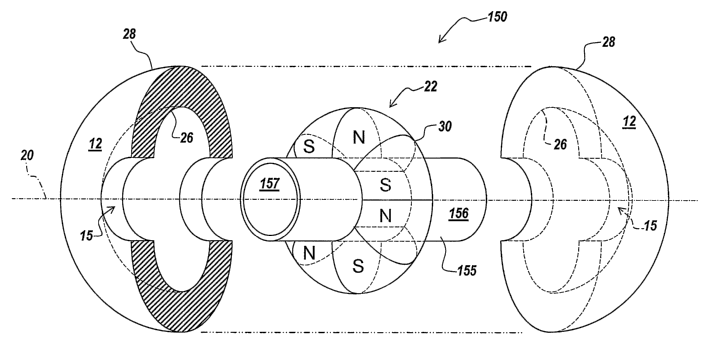
Figure 15 illustrates another exploded view of a rotational apparatus in
accordance with the teachings of the present invention. The rotational
apparatus 150
CA 02596268 2007-07-27
WO 2006/081488 PCT/US2006/003072
-19-
includes the stator assembly 12 and the rotor assembly 22. The rotor assembly
22 can
have a continuous shaped outer rotor wall 30 that extends circumferentially
about the
longitudinal axis 20 to form an outer wall surface having a toroidal like
shape. The rotor
assembly 22 includes different portions with different magnetic polarities
such as a first
portion having a North polarity and second portion having a South polarity.
Figures 16A-16D depict partial cross-sectional views of other embodiments of
the stator assembly 12 and rotor assembly 22 in accordance with the teachings
of the
present invention. The rotational apparatus 80 depicted in Figures 16A-16D
include the
stator assembly 12, the rotor assembly 22, and the rotational element 84. The
rotor
assembly 22 and the rotational element 84 are coupled in a suitable manner.
As discussed above and below in relation to Figures 1-15, respectively, the
stator
assembly 12 and the rotor assembly 22 of the present invention are
configurable or
formable to have a number of complimentary shapes in addition to each assembly
being
configurable or formable to include a first portion 82A having a first
magnetic property
and a second portion 82B having a second magnetic property. In this manner,
the stator
assembly 12 and the rotor assembly 22 are not limited to complimentary concave
and
convex like shapes and in some embodiments have complimentary shapes as
depicted in
Figures 16A-16D. That is, the stator assembly 12 and the rotor assembly 22
according
to the teachings of the present invention are configurable and formable to
have any
number of polygon or polygon like shapes. In this manner the shape of the
stator
assembly 12 and the rotor assembly 22, for example the shape of the inner wall
of the
stator assembly 12 and the shape of the outer wall of the rotor asseinbly 12,
in
coinbination with the magnetic property configuration of the stator assembly
12 and the
rotor assembly 22 can shape the magnetic field generated by the stator
asseinbly 12 to
beneficially increase or decrease the magnetic force along the periphery of
the shaped
inner stator wall to change the drive force to the rotational element 84 and
to change the
force controlling an axial, a radial, and a tilt position of the rotational
element 84 with
respect to the axis of rotation. Those skilled in the art will appreciate the
various
magnetic property configurations of the stator assembly 12 and the rotor
assembly 22
discussed above are equally applicable to the stator assembly 12 and the rotor
assembly
22 depicted in Figures 16A-16D.
Figure 16A illustrates another suitable shape for the shaped inner stator wall
26
and a complimentary shape of the shaped outer rotor wal130. Rotational
apparatus 80
includes the shaped inner stator wall 26 of the stator assembly 12 with a
trapezoid like
shape or a hexagon like shape and the shaped outer rotor wall 30 of the rotor
assembly
22 having a trapezoid like shape or a hexagon like shape. Figure 16A depicts
one
suitable polygon shape of the shaped inner stator wall 26 and the shaped outer
wall rotor
CA 02596268 2007-07-27
WO 2006/081488 PCT/US2006/003072
-20-
wa1130 in accordance with the teachings of the present invention. Those
skilled in the
art will appreciate the shaped inner stator wall 26 and the shaped outer rotor
wa1130 can
have other suitable physical shapes and both the stator assembly 12 and the
rotor
assembly 22, alone or in combination can have various portions with various
magnetic
properties.
Figure 16B illustrates one suitable shape for the shaped inner stator wall 26
and a
complimentary shape of the shaped outer rotor wall 30. Rotational apparatus 80
includes the shaped inner stator wall 26 of the stator assembly 12 with a
triangle lilce
shape or a polygon like shape and the shaped outer rotor wall 30 of the rotor
assembly
22 having a triangle like shape or a polygon like shape. Figure 16B depicts
one suitable
polygon shape of the shaped inner stator wall 26 and the shaped outer wall
rotor wall 30
in accordance with the teachings of the present invention. Those skilled in
the art will
appreciate the shaped inner stator wa1126 and the shaped outer rotor wa1130
can have
otller suitable physical shapes and both the stator assembly 12 and the rotor
assembly 22,
alone or in combination can have various portions with various magnetic
properties.
Figure 16C illustrates one suitable shape for the shaped iimer stator wall 26
and a
complimentary shape of the shaped outer rotor wal130. Rotational apparatus 80
includes the shaped inner stator wall 26 of the stator assembly 12 with a
convex like
shape and the shaped outer rotor wall 30 of the rotor assembly 22 having a
concave like
shape. Figure 16C depicts one suitable shape of the shaped inner stator wall
26 and the
shaped outer wall rotor wall 30 in accordance with the teachings of the
present
invention. Those skilled in the art will appreciate the shaped inner stator
wall 26 and the
shaped outer rotor wall 30 can have other suitable physical shapes and both
the stator
assembly 12 and the rotor assembly 22, alone or in combination can have
various
portions with various magnetic properties.
Figure 16D illustrates one suitable shape for the shaped inner stator wall 26
and a
complimentary shape of the shaped outer rotor wa1130. Rotational apparatus 80
includes the shaped inner stator wall 26 of the stator assembly 12 with a
triangle like
shape or a polygon like shape and the shaped outer rotor wall 30 of the rotor
assembly
22 having a triangle like shape or a polygon like shape. Figure 16D depicts
one suitable
polygon shape of the shaped inner stator wall 26 and the shaped outer wall
rotor wal130
in accordance with the teachings of the present invention. Those skilled in
the art will
appreciate the shaped inner stator wa1126 and the shaped outer rotor wall 30
can have
other suitable physical shapes and both the stator assembly 12 and the rotor
assembly 22,
alone or in combination can have various portions with various magnetic
properties.
The various embodiments of the above described fluid movement apparatus and
rotational apparatus are well suited for use in various industries such as
boating, air
CA 02596268 2007-07-27
WO 2006/081488 PCT/US2006/003072
-21-
handling, petroleum, chemical, pharmaceutical, medical, automotive, aeronautic
and
other commercial, residential and industrial applications.
While the present invention has been described with reference to illustrative
embodiments thereof, one skilled in the art will appreciate that there are
changes in form
and detail that may be made without departing from the intended scope of the
present
invention as defined in the pending claims. For example, the stator assembly
12 can
have an outer wall with a shape different from a convex shape, such as a
square shape, a
rectangle shape, an elliptical shape, and the like. Additionally, the stator
assembly 12
can include a number of poles in locations to increase the drive force on a
rotational
element with an increase of magnitude of current supplied to the stator
assembly 12
without substantially increasing the control forces (i.e. magnetic bearing
forces) that
control a radial, an axial, and a tilt position of the rotational element
about an axis of
rotation. Further, the stator assembly 12 can include a number of poles to
increase the
magnetic force generated to control the position (i.e., magnetic bearing
forces) on the
rotational element with an increase in magnitude of current applied to the
stator
assembly 12 without increasing the drive to the rotational element.