Language selection

Search

Patent 2596313 Summary

Third-party information liability

Some of the information on this Web page has been provided by external sources. The Government of Canada is not responsible for the accuracy, reliability or currency of the information supplied by external sources. Users wishing to rely upon this information should consult directly with the source of the information. Content provided by external sources is not subject to official languages, privacy and accessibility requirements.

Claims and Abstract availability

Any discrepancies in the text and image of the Claims and Abstract are due to differing posting times. Text of the Claims and Abstract are posted:

  • At the time the application is open to public inspection;
  • At the time of issue of the patent (grant).
(12) Patent Application: (11) CA 2596313
(54) English Title: PRESSURE VALVE
(54) French Title: SOUPAPE DE SECURITE
Status: Deemed Abandoned and Beyond the Period of Reinstatement - Pending Response to Notice of Disregarded Communication
Bibliographic Data
Abstracts

English Abstract


The Pressure Valve can control the passage that the source pass through. The
effective area of the measuring element is smaller before the valve opens,
and the effective area of the measuring element is larger when the valve
opens. Higher source pressure is needed to open the valve and lower source
pressure is needed to keep it open. The magnetic force between the magnet
and the diaphragm attracts the diaphragm toward the magnet, the force is
much stronger when the diaphragm contacts the magnet. With the help of
magnetic force, the source pressure needs to go down more to make the
spring force to overcome the magnetic force and source pressure, the valve
close at lower source pressure. It provides a method to prevent fluid from
flowing from target end to the source end when the source pressure goes
down to certain level. The Pressure Valve is designed for expansion tank of
a boiler system. With the Pressure Valve, an expansion tank can be
pre--presurized with vapor, and will have more capacity.


Claims

Note: Claims are shown in the official language in which they were submitted.

CLAIMS
THE EMBODIMENTS OF THE INVENTION IN WHICH AN
EXCLUSIVE PROPERTY OR PRIVILEGE IS CLAIMED ARE
DEFINED AS FOLLOWS:
1. The Pressure Valve comprising: first body section, a diaphragm set, a
spring, and a second body section.
2. The Pressure Valve in claim 1 comprising means to open and close
the passage at different source pressure.
3. The Pressure Valve in claim 1 comprising means to open the said
passage at higher source pressure and keep it open to let source flow
6B

forward and backward if the source pressure is above certain level
(lower than the opening pressure).
4. The Pressure Valve in claim 1 comprising means to close the said
passage at certain lower source pressure to prevent more fluid from
flowing from target end to source end.
5. The first body section in claim 1 comprising an inlet opening, a
threaded portion, a hexagon, a disc seat, two outlet openings, a
diaphragm seat, and a molding portion.
6. The diaphragm set in claim 1 consists of a disc, a diaphragm, and a
rod.
7. The said diaphragm in claim 6 has magnetic material embeded.
8. The said means in claim 3 is that the said Pressure Valve has a smaller
effective area exposed to the source pressure before the passage
opens, and a larger effective area exposed to the source pressure after
the passage opens.
9. The second body section consists of a larger portion, an embeded
magnet, a smaller portion, and an end.
10.The said means in claim 4 is that the Pressure Valve has attractive
magnetic force between the diaphragm and the magnet and the said
force is much stronger when the diaphragm contacts the magnet, once
the spring force can overcome the magnetic force and the source
pressure, it can push it further to make the disc contact disc seat to
close the valve.
7

Description

Note: Descriptions are shown in the official language in which they were submitted.


CA 02596313 2007-07-31
PRESSURE VALVE
BACKGROUND OF THE INVENTION
Expansion tank is an important device for boiler system. The boiler system
works under pressure, when the temperature goes up, the liquid (water)
expands and the pressure goes higher, when the temperature cools down, the
liquid (water) contracts and pressure goes lower. Since liquid (water) is
difficult to be compressed but vapor is easy to be compressed; the expansion
tank is introduced to help stabalize the pressure of the boiler system, it
absorbs liquid (water) from boiler system when liquid (water) in the boiler
system is heated up and releases liquid (water) when liquid (water) in the
boiler system cool down. The larger boiler system has bigger expansion
tank, before the boiler system reaches the working pressure, half of the
expansion tank will be filled with vapor and another half filled with
liquid(water); the expansion tank will lose half capacity and the boiler
system need more liquid (water).
SUMMARY OF THE INVENTION
The Pressure Valve can control the passage that the source pass through. It
consists of valve body, diaphragm, spring, and disc. The diaphragm is
measuring element after the valve opens and the disc is the measuring
element before valve opens. The spring is loading element. The disc and disc
seat on the valve body form the restricting element. The effective area of the
measuring element is smaller before the valve opens, and the effective area
of the measuring element is larger when the valve opens. Higher source
2of10

CA 02596313 2007-07-31
pressure is needed to open the valve, but lower source pressure can keep it
open. The magnetic force between the magnet and the diaphragm attracts the
diaphragm toward the magnet, the force is much stronger when the
diaphragm contacts the magnet. With the help of magnetic force, the the
source pressure needs to go down more to make the spring force to
overcome the magnetic force and source pressure, the valve close at lower
source pressure. The Pressure Valve provides a method to prevent fluid from
flowing from target end to the source end when the source pressure goes
lower than certain level. The Pressure Valve is designed for expansion tank,
which is an important device for boiler system. With Pressure Valve, the
expansion tank can be pre-presurized with vapor and will have more
capacity .
In the drawings, which form part of the description,
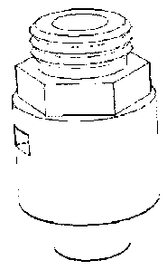
Figure 1 is drawing of outward appearance of Pressure Valve.
Figure 2 is sectional drawing of Pressure Valve before molded.
Figure 3 is sectional drawing of Pressure Valve after molded.
Figure 4 is sectional drawing of first body section.
Figure 5 is drwaing of diaphragm set.
Figure 6 is sectional drawing of second body section.
DETAIL DESCRIPTION OF THE INVENTION
Pressure Valve comprises a first body section 1, a diaphragm set 2, a spring
3, and a second body section 4. The Pressure Valve will open the passage
3of10

CA 02596313 2007-07-31
when the pressure of the working source reaches or above certain level.
Since the area of central hole of the disc seat 9 is smaller than the disc 12,
it
needs lower pressure to keep the valve open than to open the valve.
Figure 2 and figure 3 show the difference of the molding portion 5 of first
body section 1 before molded and after molded.
In figure 4, the first body section 1 consists of an inlet opening 6, a
threaded
portion 7, a hexagon 8, a disc seat 9, two outlet openings 10, a diaphragm
seat 11, and a molding portion 5. The inlet opening 6 is for communicating
fluid to the source. The threaded portion 7 is to fit the Pressure Valve to an
application. The hexagon 8 is for tighting the Pressure Valve onto an
application or loosing the Pressure Valve from an application. The disc seat
9 forms restricting element with the disc 12 of diaphragm set 2. The outlet
openings 10 is for communicating fluid to the target. The diaphragm seat 11
is for holding diaphragm 13 on position. The molding portion 5 is to
assemble the Pressure Valve by molding the second body section 4 on
position.
As seen in figure 5, diaphragm set 2 comprises a disc 12, a diaphragm 13,
and a rod 14. The disc 12 forms restricting element with the disc seat 9 of
first body section 1. The disc 12 is the measuring element before the valve
opens. The diaphragm 13 is meassuring element after the valve opens, it
senses the pressure of the source. The diaphragm 13 has some magnetic
material inside, which is attracted by the magnet 16 of the second body
section 4. The rod 14 connects the diaphragm 13 and the disc 12 so they can
move together.
4of10

CA 02596313 2007-07-31
As seen in figure 3, the spring 3 is a loading element. It resists the
diaphragm 13 to move down when the pressure of the source is higher and
forces the diaphragm 13 to move up when the pressure of the source goes
lower.
As seen in figure 6, second body section 4 comprising a larger portion 15, an
embeded magnet 16, a smaller portion 17, and an end 18. The top rim of the
larger portion 15 will hold the diaphragm 13 on position against the
diaphragm seat 11 of first body section 1, The cavity of the larger portion 15
is where the diaphragm 13 will stay and move. The embeded magnet 16 can
attract the diaphragm 13 toward itself, and the attractive force is stronger
when the diaphragm 13 contacts the magnet 16. The smaller portion 17
provides room for the spring 3 and rod 14 of the diaphragm set 2. The end
18 of the second body section 4 holds the spring 3.
The part area of disc 12 which exposed to the source before the valve opens
is smaller than the area of diaphragm 13, higher pressure needs to open the
valve than to hold the valve open. Once the pressure can open the valve, the
pressure can push the diaphragm 13 down more, with the help of the
magnetic force between the magnet 16 and diaphragm 13, the diaphragm 13
moves to the limits where the diaphragm 13 contacts the magnet 16. The
magnetic force of the magnet 16 to attract diaphragm 13 is much stronger
when the diaphragm 13 contacts the magnet 16. Once the Pressure Valve is
wide opened, the diaphragm 13 contacts magnet 16, the spring force need to
overcome the stronger magnetic force and the pressure of the source; the
pressure of source need to be lowered more to make the diaphragm 13 leave
5of10

CA 02596313 2007-07-31
magnet 16. Once the pressure of the source is low enough to make the
diaphragm 13 leave the magnet 16, the spring force can force the diaphragm
set 2 down more to make the disc 12 contact the disc seat 9. After the disc
12 contacts the disc seat 9, the measuring area reduces, the disc 12 is forced
down more or held tighter against disc seat 9.
The Pressure Valve is designed for expansion tank, which is an important
device of boiler system. The Pressure Valve should be located at the bottom
of the expansion tank. When the intake opening of the expansion tank is on
the top, an extension tube can be used to dip the Pressure Valve to the
bottom of expansion tank. With Pressure Valve, the expansion tank can be
pre-presurized with vapor, and the vapor will be kept in the expansion tank
at certain pressure level. The expansion tank will have more capacity.
C~~~~~

Representative Drawing
A single figure which represents the drawing illustrating the invention.
Administrative Status

2024-08-01:As part of the Next Generation Patents (NGP) transition, the Canadian Patents Database (CPD) now contains a more detailed Event History, which replicates the Event Log of our new back-office solution.

Please note that "Inactive:" events refers to events no longer in use in our new back-office solution.

For a clearer understanding of the status of the application/patent presented on this page, the site Disclaimer , as well as the definitions for Patent , Event History , Maintenance Fee  and Payment History  should be consulted.

Event History

Description Date
Inactive: Dead - No reply to Office letter 2010-01-18
Application Not Reinstated by Deadline 2010-01-18
Deemed Abandoned - Failure to Respond to Maintenance Fee Notice 2009-07-31
Application Published (Open to Public Inspection) 2009-01-31
Inactive: Cover page published 2009-01-30
Inactive: Abandoned - No reply to Office letter 2009-01-19
Inactive: Correction to amendment 2008-10-17
Amendment Received - Voluntary Amendment 2008-08-12
Inactive: Office letter 2008-07-23
Amendment Received - Voluntary Amendment 2008-05-22
Inactive: S.30(2) Rules - Examiner requisition 2008-04-08
Inactive: First IPC assigned 2008-01-18
Inactive: IPC assigned 2008-01-18
Inactive: IPC assigned 2007-12-21
Inactive: First IPC assigned 2007-12-21
Amendment Received - Voluntary Amendment 2007-11-14
Inactive: Office letter 2007-09-07
Application Received - Regular National 2007-09-05
Letter Sent 2007-09-05
Inactive: Filing certificate - RFE (English) 2007-09-05
All Requirements for Examination Determined Compliant 2007-07-31
Request for Examination Requirements Determined Compliant 2007-07-31
Small Entity Declaration Determined Compliant 2007-07-31

Abandonment History

Abandonment Date Reason Reinstatement Date
2009-07-31

Fee History

Fee Type Anniversary Year Due Date Paid Date
Application fee - small 2007-07-31
Request for examination - small 2007-07-31
Owners on Record

Note: Records showing the ownership history in alphabetical order.

Current Owners on Record
JIANMING YANG
Past Owners on Record
None
Past Owners that do not appear in the "Owners on Record" listing will appear in other documentation within the application.
Documents

To view selected files, please enter reCAPTCHA code :


To view images, click a link in the Document Description column. To download the documents, select one or more checkboxes in the first column and then click the "Download Selected in PDF format (Zip Archive)" or the "Download Selected as Single PDF" button.

List of published and non-published patent-specific documents on the CPD .

If you have any difficulty accessing content, you can call the Client Service Centre at 1-866-997-1936 or send them an e-mail at CIPO Client Service Centre.


Document
Description 
Date
(yyyy-mm-dd) 
Number of pages   Size of Image (KB) 
Abstract 2007-07-30 1 29
Description 2007-07-30 5 189
Claims 2007-07-30 2 51
Drawings 2007-11-13 3 87
Representative drawing 2008-11-05 1 7
Drawings 2007-07-30 3 281
Acknowledgement of Request for Examination 2007-09-04 1 189
Filing Certificate (English) 2007-09-04 1 169
Courtesy - Abandonment Letter (Office letter) 2009-04-13 1 164
Notice: Maintenance Fee Reminder 2009-05-03 1 120
Courtesy - Abandonment Letter (Maintenance Fee) 2009-09-27 1 172
Second Notice: Maintenance Fee Reminder 2010-02-01 1 119
Correspondence 2007-09-04 1 17
Correspondence 2008-07-22 1 19
Correspondence 2008-10-16 1 21