Sélection de la langue

Search

Sommaire du brevet 2596313 

Énoncé de désistement de responsabilité concernant l'information provenant de tiers

Une partie des informations de ce site Web a été fournie par des sources externes. Le gouvernement du Canada n'assume aucune responsabilité concernant la précision, l'actualité ou la fiabilité des informations fournies par les sources externes. Les utilisateurs qui désirent employer cette information devraient consulter directement la source des informations. Le contenu fourni par les sources externes n'est pas assujetti aux exigences sur les langues officielles, la protection des renseignements personnels et l'accessibilité.

Disponibilité de l'Abrégé et des Revendications

L'apparition de différences dans le texte et l'image des Revendications et de l'Abrégé dépend du moment auquel le document est publié. Les textes des Revendications et de l'Abrégé sont affichés :

  • lorsque la demande peut être examinée par le public;
  • lorsque le brevet est émis (délivrance).
(12) Demande de brevet: (11) CA 2596313
(54) Titre français: SOUPAPE DE SECURITE
(54) Titre anglais: PRESSURE VALVE
Statut: Réputée abandonnée et au-delà du délai pour le rétablissement - en attente de la réponse à l’avis de communication rejetée
Données bibliographiques
Abrégés

Abrégé anglais


The Pressure Valve can control the passage that the source pass through. The
effective area of the measuring element is smaller before the valve opens,
and the effective area of the measuring element is larger when the valve
opens. Higher source pressure is needed to open the valve and lower source
pressure is needed to keep it open. The magnetic force between the magnet
and the diaphragm attracts the diaphragm toward the magnet, the force is
much stronger when the diaphragm contacts the magnet. With the help of
magnetic force, the source pressure needs to go down more to make the
spring force to overcome the magnetic force and source pressure, the valve
close at lower source pressure. It provides a method to prevent fluid from
flowing from target end to the source end when the source pressure goes
down to certain level. The Pressure Valve is designed for expansion tank of
a boiler system. With the Pressure Valve, an expansion tank can be
pre--presurized with vapor, and will have more capacity.

Revendications

Note : Les revendications sont présentées dans la langue officielle dans laquelle elles ont été soumises.


CLAIMS
THE EMBODIMENTS OF THE INVENTION IN WHICH AN
EXCLUSIVE PROPERTY OR PRIVILEGE IS CLAIMED ARE
DEFINED AS FOLLOWS:
1. The Pressure Valve comprising: first body section, a diaphragm set, a
spring, and a second body section.
2. The Pressure Valve in claim 1 comprising means to open and close
the passage at different source pressure.
3. The Pressure Valve in claim 1 comprising means to open the said
passage at higher source pressure and keep it open to let source flow
6B

forward and backward if the source pressure is above certain level
(lower than the opening pressure).
4. The Pressure Valve in claim 1 comprising means to close the said
passage at certain lower source pressure to prevent more fluid from
flowing from target end to source end.
5. The first body section in claim 1 comprising an inlet opening, a
threaded portion, a hexagon, a disc seat, two outlet openings, a
diaphragm seat, and a molding portion.
6. The diaphragm set in claim 1 consists of a disc, a diaphragm, and a
rod.
7. The said diaphragm in claim 6 has magnetic material embeded.
8. The said means in claim 3 is that the said Pressure Valve has a smaller
effective area exposed to the source pressure before the passage
opens, and a larger effective area exposed to the source pressure after
the passage opens.
9. The second body section consists of a larger portion, an embeded
magnet, a smaller portion, and an end.
10.The said means in claim 4 is that the Pressure Valve has attractive
magnetic force between the diaphragm and the magnet and the said
force is much stronger when the diaphragm contacts the magnet, once
the spring force can overcome the magnetic force and the source
pressure, it can push it further to make the disc contact disc seat to
close the valve.
7

Description

Note : Les descriptions sont présentées dans la langue officielle dans laquelle elles ont été soumises.

CA 02596313 2007-07-31
PRESSURE VALVE
BACKGROUND OF THE INVENTION
Expansion tank is an important device for boiler system. The boiler system
works under pressure, when the temperature goes up, the liquid (water)
expands and the pressure goes higher, when the temperature cools down, the
liquid (water) contracts and pressure goes lower. Since liquid (water) is
difficult to be compressed but vapor is easy to be compressed; the expansion
tank is introduced to help stabalize the pressure of the boiler system, it
absorbs liquid (water) from boiler system when liquid (water) in the boiler
system is heated up and releases liquid (water) when liquid (water) in the
boiler system cool down. The larger boiler system has bigger expansion
tank, before the boiler system reaches the working pressure, half of the
expansion tank will be filled with vapor and another half filled with
liquid(water); the expansion tank will lose half capacity and the boiler
system need more liquid (water).
SUMMARY OF THE INVENTION
The Pressure Valve can control the passage that the source pass through. It
consists of valve body, diaphragm, spring, and disc. The diaphragm is
measuring element after the valve opens and the disc is the measuring
element before valve opens. The spring is loading element. The disc and disc
seat on the valve body form the restricting element. The effective area of the
measuring element is smaller before the valve opens, and the effective area
of the measuring element is larger when the valve opens. Higher source
2of10

CA 02596313 2007-07-31
pressure is needed to open the valve, but lower source pressure can keep it
open. The magnetic force between the magnet and the diaphragm attracts the
diaphragm toward the magnet, the force is much stronger when the
diaphragm contacts the magnet. With the help of magnetic force, the the
source pressure needs to go down more to make the spring force to
overcome the magnetic force and source pressure, the valve close at lower
source pressure. The Pressure Valve provides a method to prevent fluid from
flowing from target end to the source end when the source pressure goes
lower than certain level. The Pressure Valve is designed for expansion tank,
which is an important device for boiler system. With Pressure Valve, the
expansion tank can be pre-presurized with vapor and will have more
capacity .
In the drawings, which form part of the description,
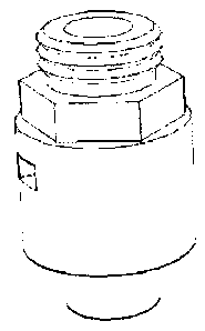
Figure 1 is drawing of outward appearance of Pressure Valve.
Figure 2 is sectional drawing of Pressure Valve before molded.
Figure 3 is sectional drawing of Pressure Valve after molded.
Figure 4 is sectional drawing of first body section.
Figure 5 is drwaing of diaphragm set.
Figure 6 is sectional drawing of second body section.
DETAIL DESCRIPTION OF THE INVENTION
Pressure Valve comprises a first body section 1, a diaphragm set 2, a spring
3, and a second body section 4. The Pressure Valve will open the passage
3of10

CA 02596313 2007-07-31
when the pressure of the working source reaches or above certain level.
Since the area of central hole of the disc seat 9 is smaller than the disc 12,
it
needs lower pressure to keep the valve open than to open the valve.
Figure 2 and figure 3 show the difference of the molding portion 5 of first
body section 1 before molded and after molded.
In figure 4, the first body section 1 consists of an inlet opening 6, a
threaded
portion 7, a hexagon 8, a disc seat 9, two outlet openings 10, a diaphragm
seat 11, and a molding portion 5. The inlet opening 6 is for communicating
fluid to the source. The threaded portion 7 is to fit the Pressure Valve to an
application. The hexagon 8 is for tighting the Pressure Valve onto an
application or loosing the Pressure Valve from an application. The disc seat
9 forms restricting element with the disc 12 of diaphragm set 2. The outlet
openings 10 is for communicating fluid to the target. The diaphragm seat 11
is for holding diaphragm 13 on position. The molding portion 5 is to
assemble the Pressure Valve by molding the second body section 4 on
position.
As seen in figure 5, diaphragm set 2 comprises a disc 12, a diaphragm 13,
and a rod 14. The disc 12 forms restricting element with the disc seat 9 of
first body section 1. The disc 12 is the measuring element before the valve
opens. The diaphragm 13 is meassuring element after the valve opens, it
senses the pressure of the source. The diaphragm 13 has some magnetic
material inside, which is attracted by the magnet 16 of the second body
section 4. The rod 14 connects the diaphragm 13 and the disc 12 so they can
move together.
4of10

CA 02596313 2007-07-31
As seen in figure 3, the spring 3 is a loading element. It resists the
diaphragm 13 to move down when the pressure of the source is higher and
forces the diaphragm 13 to move up when the pressure of the source goes
lower.
As seen in figure 6, second body section 4 comprising a larger portion 15, an
embeded magnet 16, a smaller portion 17, and an end 18. The top rim of the
larger portion 15 will hold the diaphragm 13 on position against the
diaphragm seat 11 of first body section 1, The cavity of the larger portion 15
is where the diaphragm 13 will stay and move. The embeded magnet 16 can
attract the diaphragm 13 toward itself, and the attractive force is stronger
when the diaphragm 13 contacts the magnet 16. The smaller portion 17
provides room for the spring 3 and rod 14 of the diaphragm set 2. The end
18 of the second body section 4 holds the spring 3.
The part area of disc 12 which exposed to the source before the valve opens
is smaller than the area of diaphragm 13, higher pressure needs to open the
valve than to hold the valve open. Once the pressure can open the valve, the
pressure can push the diaphragm 13 down more, with the help of the
magnetic force between the magnet 16 and diaphragm 13, the diaphragm 13
moves to the limits where the diaphragm 13 contacts the magnet 16. The
magnetic force of the magnet 16 to attract diaphragm 13 is much stronger
when the diaphragm 13 contacts the magnet 16. Once the Pressure Valve is
wide opened, the diaphragm 13 contacts magnet 16, the spring force need to
overcome the stronger magnetic force and the pressure of the source; the
pressure of source need to be lowered more to make the diaphragm 13 leave
5of10

CA 02596313 2007-07-31
magnet 16. Once the pressure of the source is low enough to make the
diaphragm 13 leave the magnet 16, the spring force can force the diaphragm
set 2 down more to make the disc 12 contact the disc seat 9. After the disc
12 contacts the disc seat 9, the measuring area reduces, the disc 12 is forced
down more or held tighter against disc seat 9.
The Pressure Valve is designed for expansion tank, which is an important
device of boiler system. The Pressure Valve should be located at the bottom
of the expansion tank. When the intake opening of the expansion tank is on
the top, an extension tube can be used to dip the Pressure Valve to the
bottom of expansion tank. With Pressure Valve, the expansion tank can be
pre-presurized with vapor, and the vapor will be kept in the expansion tank
at certain pressure level. The expansion tank will have more capacity.
C~~~~~

Dessin représentatif
Une figure unique qui représente un dessin illustrant l'invention.
États administratifs

2024-08-01 : Dans le cadre de la transition vers les Brevets de nouvelle génération (BNG), la base de données sur les brevets canadiens (BDBC) contient désormais un Historique d'événement plus détaillé, qui reproduit le Journal des événements de notre nouvelle solution interne.

Veuillez noter que les événements débutant par « Inactive : » se réfèrent à des événements qui ne sont plus utilisés dans notre nouvelle solution interne.

Pour une meilleure compréhension de l'état de la demande ou brevet qui figure sur cette page, la rubrique Mise en garde , et les descriptions de Brevet , Historique d'événement , Taxes périodiques et Historique des paiements devraient être consultées.

Historique d'événement

Description Date
Inactive : Morte - Aucune rép. à lettre officielle 2010-01-18
Demande non rétablie avant l'échéance 2010-01-18
Réputée abandonnée - omission de répondre à un avis sur les taxes pour le maintien en état 2009-07-31
Demande publiée (accessible au public) 2009-01-31
Inactive : Page couverture publiée 2009-01-30
Inactive : Abandon. - Aucune rép. à lettre officielle 2009-01-19
Inactive : Correction à la modification 2008-10-17
Modification reçue - modification volontaire 2008-08-12
Inactive : Lettre officielle 2008-07-23
Modification reçue - modification volontaire 2008-05-22
Inactive : Dem. de l'examinateur par.30(2) Règles 2008-04-08
Inactive : CIB en 1re position 2008-01-18
Inactive : CIB attribuée 2008-01-18
Inactive : CIB attribuée 2007-12-21
Inactive : CIB en 1re position 2007-12-21
Modification reçue - modification volontaire 2007-11-14
Inactive : Lettre officielle 2007-09-07
Demande reçue - nationale ordinaire 2007-09-05
Lettre envoyée 2007-09-05
Inactive : Certificat de dépôt - RE (Anglais) 2007-09-05
Toutes les exigences pour l'examen - jugée conforme 2007-07-31
Exigences pour une requête d'examen - jugée conforme 2007-07-31
Déclaration du statut de petite entité jugée conforme 2007-07-31

Historique d'abandonnement

Date d'abandonnement Raison Date de rétablissement
2009-07-31

Historique des taxes

Type de taxes Anniversaire Échéance Date payée
Taxe pour le dépôt - petite 2007-07-31
Requête d'examen - petite 2007-07-31
Titulaires au dossier

Les titulaires actuels et antérieures au dossier sont affichés en ordre alphabétique.

Titulaires actuels au dossier
JIANMING YANG
Titulaires antérieures au dossier
S.O.
Les propriétaires antérieurs qui ne figurent pas dans la liste des « Propriétaires au dossier » apparaîtront dans d'autres documents au dossier.
Documents

Pour visionner les fichiers sélectionnés, entrer le code reCAPTCHA :


Pour visualiser une image, cliquer sur un lien dans la colonne description du document. Pour télécharger l'image (les images), cliquer l'une ou plusieurs cases à cocher dans la première colonne et ensuite cliquer sur le bouton "Télécharger sélection en format PDF (archive Zip)" ou le bouton "Télécharger sélection (en un fichier PDF fusionné)".

Liste des documents de brevet publiés et non publiés sur la BDBC .

Si vous avez des difficultés à accéder au contenu, veuillez communiquer avec le Centre de services à la clientèle au 1-866-997-1936, ou envoyer un courriel au Centre de service à la clientèle de l'OPIC.


Description du
Document 
Date
(aaaa-mm-jj) 
Nombre de pages   Taille de l'image (Ko) 
Abrégé 2007-07-30 1 29
Description 2007-07-30 5 189
Revendications 2007-07-30 2 51
Dessins 2007-11-13 3 87
Dessin représentatif 2008-11-05 1 7
Dessins 2007-07-30 3 281
Accusé de réception de la requête d'examen 2007-09-04 1 189
Certificat de dépôt (anglais) 2007-09-04 1 169
Courtoisie - Lettre d'abandon (lettre du bureau) 2009-04-13 1 164
Avis de rappel: Taxes de maintien 2009-05-03 1 120
Courtoisie - Lettre d'abandon (taxe de maintien en état) 2009-09-27 1 172
Deuxième avis de rappel: taxes de maintien 2010-02-01 1 119
Correspondance 2007-09-04 1 17
Correspondance 2008-07-22 1 19
Correspondance 2008-10-16 1 21