Note: Descriptions are shown in the official language in which they were submitted.
CA 02596734 2007-08-02
WO 2006/081657 PCT/CA2006/000129
TORQUE LIMITED DECOUPLER
FIELD OF THE INVENTION
[0001] The present invention relates to a belt drive assembly for driving belt
driven
accessories in an engine of an automotive vehicle, and more particularly, to a
decoupling
mechanism for allowing the belt driven accessories to operate temporarily at a
speed other
than the endless drive assembly and for isolating the torsion spring
from'excessive torques.
BACKGROUND OF THE INVENTION
[0002] An automotive vehicle engine transfers a portion of the engine output
to a
plurality of belt driven accessories utilizing an endless serpentine belt.
Typically, each
component includes an input drive shaft and a pulley coupled to a distal end
of the drive shaft
for driving engagement with the belt. An example of such a belt driven
accessory is an
alternator.
[0003] A decoupler is operatively coupled between the pulley and the
alternator to allow
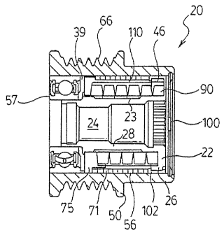
the alternator drive shaft to "overrun" or rotate at a faster speed than the
pulley and to allow
the speed of the pulley to oscillate with respect to the alternator drive
shaft due to oscillations
in the engine speed. Examples of decouplers are disclosed in United States
Patent 6,083,130,
issued to Mevissen et al. on July 4; 2000, United States Patent 5,139,463,
issued to Bytzek et
al. on August 18, 1992 and International Patent application no. WO
2004/011818.
[0004] In PCT application no. WO 2004/011818, the decoupler reduces torsional
fluctuations in the endless drive system. However, in certain applications in
which the engine
has an aggressive start profile or during conditions of rapid acceleration
during a wide open
throttle shift, the torques transmitted will over-stress the torsion spring
reducing long term
durability of the decoupler.
SUMMARY OF THE INVENTION
[0005] The disadvantages of the prior art may be overcome by providing a
decoupler that
prevents torques above a predetermined torque value from overstressing the
torsion spring.
[0006] According to one aspect of the invention, a decoupler assembly is
provided for
transferring torque between a shaft and a drive belt. The decoupler assembly
includes a hub
configured to be fixedly secured to the shaft. A carrier is rotatably mounted
on the hub. A
torsion spring extends between the hub and.the carrier for transferring torque
therebetween. A
1
CA 02596734 2007-08-02
WO 2006/081657 PCT/CA2006/000129
pulley is rotatably coupled to the hub. The pulley has an inner surface formed
therein. A
clutch spring is secured to the carrier and has a plurality of helical coils
frictionally engaging
with the inner surface of the pulley to selectively couple the hub and pulley.
The torsion
spring and the clutch spr ing are mounted co-axially and wound in opposite
senses enabling
the clutch spring to expand into, gripping engagement with the inner surface
during
acceleration of the pulley relative to the hub and to contract out of gripping
engagement with
the inner surface during deceleration of the pulley relative to the hub, while
enabling the
torsion spring to absorb minor torsional vibrations without decoupling the
pulley from the
hub. A torque limiter, in the form of a sleeve, is fitted about the torsion
spring and is sized to
limit expansion of the torsion spring enabling the torsion spring to fully
couple the hub with
the pulley at or above a predetermined torque.
[0007] According to another aspect of the invention, the torque limiter is in
the form of a
wire coil, which is fitted about the torsion spring and is sized to limit
expansion of the torsion
spring enabling the torsion spring to fully couple the hub, with the pulley at
or above a
predetermined torque.
BRIEF DESCRIPTION OF THE DRAWINGS
[0008] Advantages of the present invention will be readily appreciated as the
same
becomes better understood by reference to the following detailed description
when
considered in connection with the accompanying drawings wherein:
[0009] Figure 1 is a front view of an-engine of an automotive vehicle
incorporating a
decoupler assembly according to one aspect of the invention;
[0010] Figure 2 is an'enlarged fragmentary sectional view of the decoupler
assembly;
[0011] Figure 3 is an exploded perspective view of a clutch spring in the
decoupler
assembly of Figure 2;
[0012] Figure 4 is an exploded perspective view of the clutch spring and
carrier assembly
in relation to the torque limiter and torsion spring of the decoupler assembly
of Figure 2;
[0013] Figure 5 a perspective view of the clutch spring of the decoupler
assembly of
Figure 2;
[0014] Figure 6 is a perspective view of the carrier of the decoupler assembly
of Figure 2;
[0015] Figure 7 is a perspective view of the clutch spring and carrier
assembly of Figure
2;
2
CA 02596734 2007-08-02
WO 2006/081657 PCT/CA2006/000129
[0016] Figure 8 is a perspective view of a second embodiment of the torque
limiter of the
decoupler assembly of Figure 2;
[0017] Figure 9a is a perspective view of a third embodiment of the torque
limiter of the
decoupler assembly of Figure 2;
[0018] Figure 9b is a perspective view of an alternate third embodiment of the
torque
limiter of the decoupler assembly of Figure 2;
[0019] Figure 10 is an exploded perspective view of the decoupler assembly of
a fourth
embodiment of the, decoupler assembly of the present invention;
[0020] Figure 11 is an exploded perspective view of the clutch spring and
carrier
assembly in relation to a torque limiter and torsion spring of the decoupler
assembly of
Figure 10;
[0021] Figure 12 a perspective view of the clutch spring of the decoupler
assembly of
Figure 10;
[0022] Figure 13 is a perspective view of the carrier of the decoupler
assembly of Figure
10; and
[0023] Figure 14 is a perspective view of the clutch spring and carrier
assembly of Figure
10.
DETAILED DESCRIPTION OF THE PREFERRED EMBODIMENTS
[0024] An engine for an automotive vehicle is generally indicated at 10 in
Figure 1. The
engine 10 includes a crankshaft 12 driving an endless serpentine belt 14, as
commonly known
by those having ordinary skill in the art. The engine 10 also includes a belt
driven accessory
16 driven by the belt 14. Described in greater detail below, a decoupler
assembly 20 is
operatively assembled between the belt 14 and the belt driven accessory 16 for
automatically
decoupling the belt driven accessory 16 from the belt 14 when the belt 14
decelerates relative
to the belt driven accessory 16 and allowing the speed of the belt 14 to
oscillate relative to the
belt driven accessory 16. Additionally, a detailed description of the
structure and function of
a decoupler assembly can be found in applicant's United States Patent
6,083,130, which
issued on July 4, 2000 and PCT application no. WO 2004/011818, the contents of
which are
incorporated herein by reference.
[0025] Referring to Figures 2 and 3, the decoupler assembly 20 generally
includes a hub
22, a pulley 50, a clutch assembly 70, a torsion spring 90 and a torque
limiter 110. In the first
embodiment, the torque limiter 110 is preferably a sleeve.
3
CA 02596734 2007-08-02
WO 2006/081657 PCT/CA2006/000129
[0026] Hub 22 has a generally cylindrical body 28 having an axially extending
bore 24
and a flange 26 at one end thereof. Flange 26 has a generally helical first
slot 46 on an inner
face thereof. Since the slot 46 is helical, the slot 46 will have a step. The
bore 24 is
configured for fixedly securing the hub 22 to a drive shaft extending from the
belt driven
accessory 16.
[0027] A pulley 50 is rotatably journaled to the hub 22. A ball bearing
assembly 57 is
coupled between the pulley 50 and the hub 22 at a distal end while a bushing
journal 102
mounts the pulley 50 on the circumferential face of flange 26. The bearing
assembly 57 is
conventional comprising an inner race, an outer race and a plurality of ball
bearings rollingly
engaged therebetween. The pulley 50 typically includes a plurality of V-shaped
grooves 68
formed on the outer periphery for engaging and guiding the belt 14. Other belt
or chain
profiles may be utilized to facilitate other drive configurations, well known
in the art.
[0028] A one-way clutch assembly 70 is operatively coupled between the hub 22
and the
pulley 50. The clutch assembly 70 includes a clutch spring 71 and a carrier
75. The clutch
spring 71 includes a plurality of helical coils 72. Preferably, the clutch
spring 71 is formed
from an uncoated, spring steel material and has a non-circular cross-section
to improve
frictional contact. Most preferably, the cross-section of clutch spring 71 is
rectangular or
square. The clutch spring. 71 is press fitted into frictional engagement with
the inner surface
56 of the pulley 50. Preferably, a lubricant similar or compatible with grease
used in the ball
bearing assembly 57 is applied to minimize wear between the clutch spring 71
and the inner
surface 56 of the pulley 50.
[0029] The carrier 75 is rotatably mounted on the hub 22. The carrier 75 is
generally ring
shaped and has an inner face 78, a bore 80 and an outer circumferential
surface 82. A slot 84
is formed on the inner face 78 and is configured to retain an end of the
clutch spring 71. A
generally helical second slot 86 is also formed on the inner face 78 and
inside of slot 84,
defining a second locating surface 88 and a step.
[0030] An annular thrust washer 39 is seated against the end of the carrier 75
and abuts
against the inner bearing race of bearing assembly 57. The outer periphery of
the thrust
washer 39 is circular with a step 41 to complementarily fit with a tab. Thrust
washer 39 has
one or more radial or circumferential serrations 43 to engage hub 22 and
mechanically lock
the thrust washer 39 to the hub 22 to prevent relative motion therebetween.
[0031] A helical torsion spring 90 is axially compressed between the hub 22
and the
carrier 75. The torsion spring 90 and the clutch spring 71 are co-axial and
typically coiled in
4
CA 02596734 2007-08-02
WO 2006/081657 PCT/CA2006/000129
opposite directions. In certain applications, the torsion spring 90 and clutch
spring 71 can be
wound in the same sense to produce a desired decoupling action. One end of the
torsion
spring 90 is retained in the first slot 46 of the hub 22 and the other end is
retained in the slot
86 of the carrier 75. Axial forces due to the compression of the torsion
spring 90 retain the
carrier 75 in abutting engagement with the thrust washer 39.
[0032] Typically, the shaft of the hub 22 has an area of reduced diameter 23
to provide
clearance between the torsion spring 90 and the shaft 28 of hub 22 to prevent
uncontrolled
contact and friction wear at the interface between shaft 28 and torsion spring
90. Thus, the
torsion spring 90 allows relative movement between the carrier 75 and the hub
22 to
accommodate minor variations in the speed of the pulley 50 due to oscillations
in the
operating speed of the engine. The oscillations are not sufficient to activate
the clutch
assembly 70.
[0033] A torque limiter 110 is wrapped about the torsion spring 90 in a
surrounding
relation. Preferably, torque limiter 110 has a split or opening 112 and a
cir=cumferentially
extending shoulder step 114. Shoulder step 114 configures the torque limiter
110 to
complementarily fit with bushing 102 mounted on the flange 26 of hub 22. In a
first
preferred embodiment, torque limiter 110 is an organic resinous material,
preferably a
NylonTM material, with or without reinforcement material such as glass fibres,
etc. Torque
limiter 110 has a thickness selected to take up the play between the torsion
spring 90, the
clutch spring 71 and the inside diameter of the pulley 50. As torque
increases, the torsional
spring 90 expands outwardly until physically constrained by the torque limiter
110 against
the clutch spring 71 and the inside diameter of bore 56. When the radial
clearance between
the torsion spring 90, torque limiter 110, the clutch spring 71 and the inside
bore 56 of the
pulley 50 is closed, the spring 90 is prevented from further expanding,
locking the decoupler
10, coupling the hub 22 with the pulley 50. In other words, the torque limiter
110 limits the
amount of outward expansion of the torsion spring 90, preventing overloading
of the torsion
spring 90. The amount of radial expansion of the torsion spring 90 can be
calculated and the
torque limiter 110 can be designed to ensure that the torque transferred
through the torsion
spring 90 is maintained below a predetermined torque value.
[0034] A second embodiment of the sleeve is illustrated in Figure 8. Torque
limiter 110'
is a closed metal ring. The metal ring would only expand to a relatively small
degree,
directly limiting outward expansion of the torsion spring 90.
CA 02596734 2007-08-02
WO 2006/081657 PCT/CA2006/000129
[0035] A third embodiment of the sleeve is illustrated in Figure 9a. Torque
limiter 110"
has a plurality of axially elongate openings 116 spaced circumferentially
spaced about the
torque limiter 110". The openings 116 enable the grease lubricant to travel
outwardly to the
clutch spring 71.
[0036] An alternative third embodiment of the sleeve is illustrated in Figure
9b. The
torque limiter 110* has a series of circumferentially spaced openings 116* and
117.
Preferably, openings 116* are elongate and openings 117 are circular and
spaced in a regular
pattern, resembling dimples on a golf ball. Additionally, torque limiter 110*
has an integrally
extending radial flange 119 that acts a thrust bearing.
[0037] A cap 100 is attached to the end of pulley 50 for preventing
contaminants from
entering the decoupler assembly 20 and for retaining the lubricant within the
decoupler
assembly 20.
[0038] In operation, the engine 10 is started and the pulley 50 is accelerated
and rotated
in a driven direction by the belt 14 driven by the engine 10. Acceleration and
rotation of the
pulley 50 in the driven direction relative to the hub 22 creates friction
between the inner
surface 56 of the pulley 50 and preferably all of the coils 72 of the
clutch.spring 71. It should
be appreciated that the clutch spring 71 will function even where at the onset
at least one of
the coils 72 of the clutch spring 71 is frictionally engaged with the inner
surface 56 of the
pulley, 50. The clutch spring 71. is helically coiled such that the friction
between the inner
surface 56 of the pulley 50 and at least one of the coils 72 would cause the
clutch spring 71 to
expand radially outwardly toward and grip the inner surface 56 of the pulley
50. Continued
rotation of the pulley 50 in the driven direction relative to the hub 22 would
cause a generally
exponential increase in the outwardly radial force applied by the coils 72
against the inner
surface 56 until all of the coils 72 of the clutch spring 71 become fully
brakingly engaged
with the pulley 50. When the clutch spring 71 is fully engaged with the inner
surface 56, the
rotation of the pulley 50 is fully directed toward rotation of the drive shaft
15 of the belt
driven accessory 16. Additionally, centrifugal forces help to retain the
clutch spring 71 in
braking engagement with the inner surface 56 of the pulley 50.
[0039] The rotational movement of the carrier 75 in the driven direction is
transferred to
the hub 22 by the torsional spring 90 such that the carrier 75, thrust washer
39, hub 22, and
the drive shaft 15 from the belt driven accessory 16 rotate together with the
pulley 50.
Additionally, the torsional spring 90 resiliently allows relative movement
between the carrier
6
CA 02596734 2007-08-02
WO 2006/081657 PCT/CA2006/000129
75 and the hub 22 to accommodate oscillations in the speed of the pulley 50
due to
corresponding oscillations in the operating speed of the engine 10.
[00401 When the pulley 50 decelerates, the hub 22 driven by the inertia
associated with
the rotating drive shaft 15 and the rotating mass within the belt driven
accessory 16 will
initially "overrun" or continue to rotate in the driven direction at a higher
speed than the
pulley 50. More specifically, the higher rotational speed of the hub 22
relative to the pulley
50 causes the clutch spring 71 to contract radially relative to the inner
surface 56 of the pulley
50. The braking engagement between the clutch spring 71 and the pulley 50 is
relieved,
thereby allowing overrunning of the hub 22 and drive shaft 15 from the belt
driven accessory
16 relative to the pulley 50. The coils 72 may remain frictionally engaged
with the inner
surface 56 while the pulley 50 decelerates relative to the clutch assembly 70
and the hub 22.
The coils 72 of the clutch spring 71 begin to brakingly reengage the inner
surface 56 as the
pulley 50 accelerates beyond the speed of the hub 22.
[0041] In conditions of high loading, such as a fast engine start profile
and/or rapid
acceleration during a wide open throttle shift, the coils of the torsion
spring 90 will be urged
to expand outwardly, due to relative rotation between the hub 22 and the
pulley 50. The
torsion spring 90 will expand, frictionally engaging the torque limiter 110
which will then
engage the clutch spring 71. Full frictionally engagement is selected to'
occur at a
predetermined toque value by selecting the thickness of the torque limiter
110. Once fully
engaged, the hub 22 will be locked with the pulley 50 and torques above a
predetermined
torque value will be transmitted directly therebetween. Thus, the higher
torques do not
overstress the torsion spring 90 and ultimately improving durability of the
decoupler
assembly 10.
[0042] Referring to Figures 10 to 14, a fourth embodiment of the torque
limiter 110 is
illustrated. Elements common with the embodiment of Figure 2 and 3 retain the
same
reference number.
[0043] In this embodiment, the torque limiter 110"' is in the form of a wire
coil spring.
Torque limiter 110"' is positioned about the torsion spring 90. Preferably,
torque limiter
110"' is formed of a small gauge wire, compared to torque spring 90, with a
square or
rectangular cross-section. The gauge and dimensions of torque limiter 110"'
are selected
such that any play which would otherwise be present between torsion spring 90,
clutch spring
71 and the inside surface 56 of pulley 50 is substantially removed, while
still allowing
7
CA 02596734 2007-08-02
WO 2006/081657 PCT/CA2006/000129
relative motion between torsion spring 90 and clutch spring 71. Further, the
coils of torque
limiter 110"' allow grease, or any other lubricant, to travel outwardly to the
clutch spring 71.
[0044] It is presently preferred that the coils of torque limiter 110"' be
wound in the
same sense of the coils of clutch spring 71, although this is not essential to
proper operation
of decoupler 20.
[0045] As torque to pulley 50 increases, torsional spring 90 expands outwardly
until
physically constrained by torque limiter 110"'. When the radial clearance
between torsion
spring 90, torque limiter 110"', clutch spring 71 and the inside surface 56 of
pulley 50 is
closed, spring 90 is prevented from further expanding, locking decoupler 20,
coupling the
hub 22 with the pulley 50. In other words, torque limiter 110"' limits the
amount of outward
expansion of the torsion spring. 90, preventing overloading of torsion spring
90.
[0046] The amount of radial expansion of torsion spring 90 can be pre-
determined and
torque limiter 110"' can be designed to ensure that the torque transferred
through torsion
spring 90 is maintained below a preselected torque value.
[0047] Referring to Figures 12 to 14, a second variant of the clutch assembly
70 is
illustrated. The clutch assembly 70 includes clutch spring 71', comprising a
helical coil, and
a carrier 75'. Preferably, clutch spring 71' is formed from an uncoated,
spring-steel material
and the material forming the helical windings 72 has a non-circular cross-
section to improve
frictional contact. Most preferably, the cross-section of the helical winding
material is
rectangular or square. Clutch spring 71' is press-fitted into frictional
engagement with the
inner surface 56 of the pulley 50. Preferably a lubricant, similar or
compatible with the
grease used in the ball bearing assembly 57, is applied to minimize wear
between the clutch
spring 71' and inner surface 56 of the pulley 50.
[0048] Carrier 75' is rotatably mounted on the hub 22 and carrier 75' is
generally ring
shaped, with an inner face 78, a bore 80 and an outer circumferential surface
82. A slot 84' is
formed on inner face 78 and is configured to retain an end of the clutch
spring 71'. A
generally helical second slot 86 is also formed on the inner face 78 and
inside of slot 84,
defining a second locating surface 88 and a step.
[0049] In this variant, the end of clutch spring 71' is bent at 73 and 77.
Slot 84' is
complementarily configured to receive the end of the clutch spring 71' and
frictionally
engage with the bends 73 and 77.
[0050] The bore 80 of carrier 75' has a keyway 81 and a series of axially
extending
dimples.
8
CA 02596734 2007-08-02
WO 2006/081657 PCT/CA2006/000129
[0051] The decoupler illustrated in Figures 10 to 14 operates in the same
fashion as
described with respect to the decoupler illustrated in Figure 1 to 9.
[0052] In conditions of high loading, such as a fast engine start profile
and/or rapid
acceleration during a wide open throttle shift, the coils of the torsion
spring 90 will be urged
to expand outwardly, due to relative rotation between hub 22 and pulley 50.
The torsion
spring 90 will expand, expanding torque limiter 110"" in turn, which will then
frictionally
engage the clutch spring 71. Full frictional engagement is selected to occur
at a
predetermined toque value by selecting the thickness of the windings of torque
limiter 110.
[0053] Preferably, decoupler 20 further includes an adapter 104 which is press
fit into the
inner race of bearing 57 and which allows decoupler 20 to be fit to belt
driven accessories
with drive shafts of different sizes and/or to position decoupler 20 on the
driven shaft to
ensure correct alignment of grooves 66 with the serpentine belt. However,
adapter 104 is not
necessary and decoupler 20 can be installed directly onto the drive shaft of a
belt driven
accessory if the diameter of that drive shaft will properly engage the inner
race surface of
bearing 57 and/or if grooves 66 will be properly aligned with the serpentine
belt.
[0054] The invention has been described in an illustrative manner, and it 'is
to be
understood that the terminology, which has been used, is intended to be in the
nature of
words of description rather than of limitation. Many modification and
variations of the
present invention are possible in light of the above teachings. It is,
therefore, to be
understood that within the scope of the appended claims, the invention may be
practiced
other than as specifically described.
9