Note: Descriptions are shown in the official language in which they were submitted.
CA 02596789 2007-08-09
142196
PILOT MIXER FOR MIXER ASSEMBLY OF A GAS TURBINE ENGINE
COMBUSTOR HAVING A PRIMARY FUEL INJECTOR AND A
PLURALITY OF SECONDARY FUEL INJECTION PORTS
BACKGROUND OF THE INVENTION
The present invention relates to a staged combustion system in which the
production
of undesirable combustion product components is minimized over the engine
operating regime and, more particularly, to a mixer assembly having a pilot
mixer
with a primary fuel injector and secondary fuel injection ports.
Modern day emphasis on minimizing the production and discharge of gases that
contribute to smog and to other undesirable environmental conditions,
particularly
those gases that are emitted from gas turbine engines, have led to different
combustor
designs that have been developed in an effort to reduce the production and
discharge
of such undesirable combustion product components. Other factors that
influence
combustor design are the desires of users of gas turbine engines for
efficient, low cost
operation, which translates into a need for reduced fuel consumption while at
the same
time maintaining or even increasing engine output. As a consequence, important
design criteria for aircraft gas turbine engine combustion systems include
provision
for high combustion temperatures, in order to provide high thermal efficiency
under a
variety of engine operating conditions, as well as the minimization of
undesirable
combustion conditions that contribute to the emission of particulates, and to
the
emission of undesirable gases, and to the emission of combustion products that
are
precursors to the formation of photochemical smog.
Various governmental regulatory bodies have established emission limits for
acceptable levels of unburned hydrocarbons (HC), carbon monoxide (CO), and
oxides
of nitrogen (N0x), which have been identified as the primary contributors to
the
1
CA 02596789 2007-08-09
142196
generation of undesirable atmospheric conditions. Therefore, different
combustor
designs have been developed to meet those criteria. For example, one way in
which
the problem of minimizing the emission of undesirable gas turbine engine
combustion
products has been attacked is the provision of staged combustion. In that
arrangement, a combustor is provided in which a first stage burner is utilized
for low
speed and low power conditions to more closely control the character of the
combustion products. A combination of first stage and second stage burners is
provided for higher power outlet conditions while attempting to maintain the
combustion products within the emissions limits. It will be appreciated that
balancing
the operation of the first and second stage burners to allow efficient thermal
operation
of the engine, while simultaneously minimizing the production of undesirable
combustion products, is difficult to achieve. In that regard, operating at low
combustion temperatures to lower the emissions of NOx, can also result in
incomplete
or partially incomplete combustion, which can lead to the production of
excessive
amounts of HC and CO, in addition to producing lower power output and lower
thermal efficiency. High combustion temperature, on the other hand, although
improving thermal efficiency and lowering the amount of HC and CO, often
results in
a higher output of NOx.
Another way that has been proposed to minimize the production of those
undesirable
combustion product components is to provide for more effective intermixing of
the
injected fuel and the combustion air. In that regard, numerous mixer designs
have
been proposed over the years to improve the mixing of the fuel and air. In
this way,
burning occurs uniformly over the entire mixture and reduces the level of HC
and CO
that result from incomplete combustion. Even with improved mixing, however,
higher levels of undesirable NOx are formed under high power conditions when
the
flame temperatures are high.
One mixer design that has been utilized is known as a twin annular premixing
swirler
(TAPS), which is disclosed in the following U.S. Patents: 6,354,072;
6,363,726;
6,367,262; 6,381,964; 6,389,815; 6,418,726; 6,453,660; 6,484,489; and,
6,865,889.
Published U.S. patent application 2002/0178732 also depicts certain
embodiments of
2
CA 02596789 2012-06-07
142196
the TAPS mixer. It will be understood that the TAPS mixer assembly includes a
pilot
mixer which is supplied with fuel during the entire engine operating cycle and
a main
mixer which is supplied with fuel only during increased power conditions of
the
engine operating cycle. While improvements in the main mixer of the assembly
during high power conditions (i.e., take-off and climb) are disclosed in U.S.
Published
patent applications US 2007-0028624 Al, US 2007-0028618 A1, and US 2007-
0028617 Al, modification of the pilot mixer is desired to improve operability
across
other portions of the engine's operating envelope (i.e., idle, approach and
cruise)
while maintaining combustion efficiency.
Thus, there is a need to provide a gas turbine engine combustor in which the
production of undesirable combustion product components is minimized over a
wide
range of engine operating conditions. Further, it is desired that the pilot
mixer of a
nested combustor arrangement be modified to improve operability and reduce
emissions over the engine's operating envelope.
BRIEF SUMMARY OF THE INVENTION
In a first exemplary embodiment of the invention, a mixer assembly for use in
a
combustion chamber of a gas turbine engine is disclosed as including a pilot
mixer, a
main mixer, and a fuel manifold. More specifically, the pilot mixer includes:
an
annular pilot housing having a hollow interior; a primary fuel injector
mounted in the
pilot housing and adapted for dispensing droplets of fuel to the hollow
interior of the
pilot housing; a plurality of axial swirlers positioned upstream from the
primary fuel
injector, each of the plurality of swirlers having a plurality of vanes for
swirling air
traveling through the respective swirler to mix air and the droplets of fuel
dispensed
by the primary fuel injector; and, a plurality of secondary fuel injection
ports for
introducing fuel into the hollow interior of the pilot housing. The main mixer
further
includes: a main housing surrounding the pilot housing and defining an annular
cavity; a plurality of fuel injection ports for introducing fuel into the
cavity; and, at
least one swirler positioned upstream from the plurality of fuel injection
ports, each of
the main mixer swirlers having a plurality of vanes for swirling air traveling
through
CA 02596789 2007-08-09
142196
the respective swirler to mix air and the droplets of fuel dispensed by the
main mixer
fuel injection ports. The fuel manifold is in flow communication with the
plurality of
secondary fuel injection ports in the pilot mixer and the plurality of fuel
injection ports
in the main mixer.
In a second exemplary embodiment of the invention, a method of operating a gas
turbine engine combustor having a pilot mixer and a main mixer is disclosed,
wherein
said pilot mixer includes an annular pilot housing having a hollow interior, a
primary
fuel injector mounted in the pilot housing and adapted for dispensing droplets
of fuel
to the hollow interior of the pilot housing, a plurality of axial swirlers
positioned
upstream from the primary fuel injector, wherein each of the plurality of
swirlers has a
plurality of vanes for swirling air traveling through the respective swirler
to mix air
and the droplets of fuel dispensed by the primary fuel injector, and a
plurality of
secondary fuel injection ports for introducing fuel into the hollow interior
of the pilot
housing. The method includes the steps of providing air through the swirlers
at a
designated air flow rate, providing fuel through the primary fuel injector,
and
providing fuel through the secondary fuel injection ports of the pilot mixer
during
predetermined points in an operating cycle of the gas turbine engine.
In a third exemplary embodiment of the invention, a combustor for a gas
turbine
engine is disclosed as including an outer liner, an inner liner spaced
radially from the
outer liner so as to form a combustion chamber therebetween, a dome positioned
at an
upstream end of the combustion chamber, and a plurality of mixer assemblies
positioned within openings of the dome. Each mixer assembly has a pilot mixer
which includes: an annular pilot housing having a hollow interior; a primary
fuel
injector mounted in the pilot housing and adapted for dispensing droplets of
fuel to the
hollow interior of the pilot housing; a plurality of axial swirlers positioned
upstream
from the primary fuel injector, each of the plurality of swirlers having a
plurality of
vanes for swirling air traveling through the respective swirler to mix air and
the
droplets of fuel dispensed by the primary fuel injector; and, a plurality of
secondary
fuel injection ports for introducing fuel into the hollow interior of the
pilot housing.
4
CA 02596789 2007-08-09
142196
BRIEF DESCRIPTION OF THE DRAWINGS
FIG. 1 is a diagrammatic view of a high bypass turbofan gas turbine engine;
FIG. 2 is a longitudinal, cross-sectional view of a gas turbine engine
combustor having
a staged arrangement;
FIG. 3 is an enlarged, cross-sectional view of the mixer assembly depicted in
Fig. 2;
FIG. 4 is an aft perspective view of the mixer assembly depicted in Figs. 2
and 3;
FIG. 5 is an aft perspective view of a portion of the mixer assembly depicted
in Figs.
2-4; and,
FIG. 6 is a partial perspective view of the mixer assembly depicted in Figs. 2-
4, taken
along line 6-6 in Fig. 4.
DETAILED DESCRIPTION OF THE INVENTION
Referring now to the drawings in detail, wherein identical numerals indicate
the same
elements throughout the figures, Fig. 1 depicts in diagrammatic form an
exemplary
gas turbine engine 10 (high bypass type) utilized with aircraft having a
longitudinal or
axial centerline axis 12 therethrough for reference purposes. Engine 10
preferably
includes a core gas turbine engine generally identified by numeral 14 and a
fan section
16 positioned upstream thereof. Core engine 14 typically includes a generally
tubular
outer casing 18 that defines an annular inlet 20. Outer casing 18 further
encloses and
supports a booster compressor 22 for raising the pressure of the air that
enters core
engine 14 to a first pressure level. A high pressure, multi-stage, axial-flow
compressor 24 receives pressurized air from booster 22 and further increases
the
pressure of the air. The pressurized air flows to a combustor 26, where fuel
is injected
into the pressurized air stream to raise the temperature and energy level of
the
pressurized air. The high energy combustion products flow from combustor 26 to
a
first (high pressure) turbine 28 for driving high pressure compressor 24
through a first
(high pressure) drive shaft 30, and then to a second (low pressure) turbine 32
for
CA 02596789 2007-08-09
142196
driving booster compressor 22 and fan section 16 through a second (low
pressure)
drive shaft 34 that is coaxial with first drive shaft 30. After driving each
of turbines
28 and 32, the combustion products leave core engine 14 through an exhaust
nozzle
36 to provide propulsive jet thrust.
Fan section 16 includes a rotatable, axial-flow fan rotor 38 that is
surrounded by an
annular fan casing 40. It will be appreciated that fan casing 40 is supported
from core
engine 14 by a plurality of substantially radially-extending,
circumferentially-spaced
outlet guide vanes 42. In this way, fan casing 40 encloses fan rotor 38 and
fan rotor
blades 44. Downstream section 46 of fan casing 40 extends over an outer
portion of
core engine 14 to define a secondary, or bypass, airflow conduit 48 that
provides
additional propulsive jet thrust.
From a flow standpoint, it will be appreciated that an initial air flow,
represented by
arrow 50, enters gas turbine engine 10 through an inlet 52 to fan casing 40.
Air flow
50 passes through fan blades 44 and splits into a first compressed air flow
(represented
by arrow 54) that moves through conduit 48 and a second compressed air flow
(represented by arrow 56) which enters booster compressor 22. The pressure of
second compressed air flow 56 is increased and enters high pressure compressor
24, as
represented by arrow 58. After mixing with fuel and being combusted in
combustor
26, combustion products 60 exit combustor 26 and flow through first turbine
28.
Combustion products 60 then flow through second turbine 32 and exit exhaust
nozzle
36 to provide thrust for gas turbine engine 10.
As best seen in Fig. 2, combustor 26 includes an annular combustion chamber 62
that
is coaxial with longitudinal axis 12, as well as an inlet 64 and an outlet 66.
As noted
above, combustor 26 receives an annular stream of pressurized air from a high
pressure compressor discharge outlet 69. A portion of this compressor
discharge air
flows into a mixing assembly 67, where fuel is also injected from a fuel
nozzle 68 to
mix with the air and form a fuel-air mixture that is provided to combustion
chamber
62 for combustion. Ignition of the fuel-air mixture is accomplished by a
suitable
igniter 70, and the resulting combustion gases 60 flow in an axial direction
toward and
6
CA 02596789 2007-08-09
142196
into an annular, first stage turbine nozzle 72. Nozzle 72 is defined by an
annular flow
channel that includes a plurality of radially-extending, circularly-spaced
nozzle vanes
74 that turn the gases so that they flow angularly and impinge upon the first
stage
turbine blades of first turbine 28. As shown in Fig. 1, first turbine 28
preferably
rotates high pressure compressor 24 via first drive shaft 30. Low pressure
turbine 32
preferably drives booster compressor 24 and fan rotor 38 via second drive
shaft 34.
Combustion chamber 62 is housed within engine outer casing 18 and is defined
by an
annular combustor outer liner 76 and a radially-inwardly positioned annular
combustor inner liner 78. The arrows in Fig. 2 show the directions in which
compressor discharge air flows within combustor 26. As shown, part of the air
flows
over the outermost surface of outer liner 76, part flows into combustion
chamber 62,
and part flows over the innermost surface of inner liner 78.
Contrary to previous designs, it is preferred that outer and inner liners 76
and 78,
respectively, not be provided with a plurality of dilution openings to allow
additional
air to enter combustion chamber 62 for completion of the combustion process
before
the combustion products enter turbine nozzle 72. This is in accordance with a
patent
application entitled "High Pressure Gas Turbine Engine Having Reduced
Emissions"
and having Serial No. 11/188,483, which is also owned by the assignee of the
present
invention. It will be understood, however, that outer liner 76 and inner liner
78
preferably include a plurality of smaller, circularly-spaced cooling air
apertures (not
shown) for allowing some of the air that flows along the outermost surfaces
thereof to
flow into the interior of combustion chamber 62. Those inwardly-directed air
flows
pass along the inner surfaces of outer and inner liners 76 and 78 that face
the interior
of combustion chamber 62 so that a film of cooling air is provided therealong.
It will be understood that a plurality of axially-extending mixing assemblies
67 are
disposed in a circular array at the upstream end of combustor 26 and extend
into inlet
64 of annular combustion chamber 62. It will be seen that an annular dome
plate 80
extends inwardly and forwardly to define an upstream end of combustion chamber
62
and has a plurality of circumferentially spaced openings formed therein for
receiving
7
CA 02596789 2007-08-09
142196
mixing assemblies 67. For their part, upstream portions of each of inner and
outer
liners 76 and 78, respectively, are spaced from each other in a radial
direction and
define an outer cowl 82 and an inner cowl 84. The spacing between the
forwardmost
ends of outer and inner cowls 82 and 84 defines combustion chamber inlet 64 to
provide an opening to allow compressor discharge air to enter combustion
chamber
62.
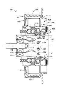
A mixing assembly 100 in accordance with one embodiment of the present
invention
is shown in FIG. 3. Mixing assembly 100 preferably includes a pilot mixer 102,
a
main mixer 104, and a fuel manifold 106 positioned therebetween. More
specifically,
it will be seen that pilot mixer 102 preferably includes an annular pilot
housing 108
having a hollow interior, as well as a primary fuel injector 110 mounted in
housing
108 and adapted for dispensing droplets of fuel to the hollow interior of
pilot housing
108. Further, pilot mixer 102 preferably includes a first swirler 112 located
at a
radially inner position adjacent primary fuel injector 110, a second swirler
114 located
at a radially outer position from first swirler 112, and a splitter 116
positioned
therebetween. As shown, splitter 116 extends downstream of primary fuel
injector
110 to form a venturi 118 at a downstream portion. It will be understood that
first and
second pilot swirlers 112 and 114 are generally oriented parallel to a
centerline axis
120 through mixing assembly 100 and include a plurality of vanes for swirling
air
traveling therethrough. Fuel and air are provided to pilot mixer 102 at all
times during
the engine operating cycle so that a primary combustion zone 122 is produced
within a
central portion of combustion chamber 62 (see Fig. 2).
Main mixer 104 further includes an annular main housing 124 radially
surrounding
pilot housing 108 and defining an annular cavity 126, a plurality of fuel
injection ports
128 which introduce fuel into annular cavity 126, and a swirler arrangement
identified
generally by numeral 130. Swirler arrangement 130 may be configured in any of
several ways, as seen in a patent application entitled "Mixer Assembly For
Combustor
Of A Gas Turbine Engine Having A Plurality Of Counter-Rotating Swirlers"
having
Serial No. 11/188,596 and a patent application entitled "Swirler Arrangement
For
Mixer Assembly Of A Gas Turbine Engine Combustor Having Shaped Passages"
8
CA 02596789 2007-08-09
142196
having Serial No. 11/188,595, both of which are assigned to the owner of the
present
invention. It will be seen in Fig. 3, however, that swirler arrangement 130
preferably
includes at least a first swirler 144 positioned upstream from fuel injection
ports 128.
As shown, first swirler 144 is preferably oriented substantially radially to
centerline
axis 120 through mixer assembly 100. It will be noted that first swirler 144
includes a
plurality of vanes 150 for swirling the air flowing therebetween. Since vanes
150 are
substantially uniformly spaced circumferentially, a plurality of substantially
uniform
passages are defined between adjacent vanes 150. It will further be understood
that
swirler 144 may include vanes having different configurations so as to shape
the
passages in a desirable manner, as disclosed in the '595 patent application
identified
hereinabove.
Swirler arrangement 130 also is shown as including a second swirler 146
positioned
upstream from fuel injection ports 128 and preferably oriented substantially
parallel to
centerline axis 120. Second swirler 146 further includes a plurality of vanes
152 for
swirling the air flowing therebetween. Although vanes 152 are shown as being
substantially uniformly spaced circumferentially, thereby defining a plurality
of
substantially uniform passages therebetween, such vanes 152 may also have
different
configurations so as to shape the passages in a desirably manner.
Fuel manifold 106, as stated above, is located between pilot mixer 102 and
main
mixer 104 and is in flow communication with a fuel supply. Fuel injection
ports 128
are in flow communication with fuel manifold 106 and spaced circumferentially
around centerbody outer shell 140. As seen in Fig. 3, fuel injection ports 128
are
preferably positioned so that fuel is provided in an upstream end of annular
cavity
126.
When fuel is provided to main mixer 104, an annular, secondary combustion zone
198
is provided in combustion chamber 62 that is radially outwardly spaced from
and
concentrically surrounds primary combustion zone 122. Depending upon the size
of
gas turbine engine 10, as many as twenty or so mixer assemblies 100 can be
disposed
in a circular array at inlet 64 of combustion chamber 62.
9
CA 02596789 2007-08-09
142196
As best seen in Figs. 3, 4, and 6, pilot mixer 102 further includes a
plurality of spaced
secondary fuel injection ports 134, whereby fuel is also introduced into
hollow interior
of pilot housing 108. It will be appreciated that secondary fuel injection
ports 134 are
preferably spaced circumferentially about pilot housing 108 within a
designated plane
136 intersecting centerline axis 120 through mixing assembly 100. While plane
136,
in which secondary fuel injection ports 134 lie, is shown as being located in
a flared
portion 138 of pilot housing 108 downstream of splitter 116, it will be
understood that
a plane containing such secondary fuel injection ports 134 may be located at
approximately a downstream end of splitter 116 or even upstream thereof.
Indeed, the
axial length of splitter 116 may be altered so that its relationship with the
location of
secondary fuel injection ports 134 could change.
Similarly, plane 136 is depicted as being oriented substantially perpendicular
to
centerline axis 120, but secondary fuel injection ports 134 may be positioned
so that
plane 136 is skewed so as to be angled either upstream or downstream as
desired.
Further, regardless of the axial position or orientation of plane 136
containing
secondary fuel injection ports 134, each such secondary fuel injection port
134 may
individually be oriented substantially perpendicular to centerline axis 120,
oriented
upstream at an acute angle, or oriented downstream at an obtuse angle.
It will further be seen that secondary fuel injection ports 134 of pilot mixer
102
preferably are in flow communication with fuel manifold 106, although it could
receive fuel from a separate source. As seen in Fig. 5, secondary fuel
injection ports
134 may be incorporated into a one piece fuel injection assembly 135 with fuel
injection ports 128 of main mixer 104. In any event, fuel is typically
injected into the
hollow portion of pilot housing 108 by secondary fuel injection ports 134 upon
the
occurrence of a specified event (e.g., a designated cycle point for gas
turbine engine
10, when compressor discharge air 58 is a designated temperature, etc.).
Depending
upon the requirements of a specific condition, fuel is injected through
secondary fuel
injection ports 134 at a rate greater than, less than or substantially the
same as fuel
injected through primary fuel injector 110. Of course, this presumes that fuel
will be
provided by primary fuel injector 110 at all times, but there may be occasions
when it
CA 02596789 2007-08-09
142196
is preferable to provide fuel to pilot mixer 102 only through secondary fuel
injection
ports 134.
In this way, pilot mixer 102 has greater flexibility during operation across
the lower
power conditions (i.e., idle, approach and cruise). In particular, it will be
appreciated
that pilot mixer 102 is able to power gas turbine engine 10 up to
approximately 30%
of maximum thrust when fuel is provided solely to primary fuel injector 110.
By
comparison, pilot mixer 102 is able to power gas turbine engine 10 up to
approximately 70% of maximum thrust when fuel is provided to secondary fuel
injection ports 134 as well.
In order to promote the desired fuel spray into the hollow interior of pilot
housing 108,
it is preferred that a passage 142 surround each secondary fuel injection port
134 of
pilot mixer 102. Each passage 142 is in flow communication with compressed air
via
a supply 154 adjacent to fuel manifold 106. This air is provided to facilitate
injection
of the fuel spray into pilot housing 108 instead of being forced along an
inner surface
156 thereof This may further be enhanced by providing a swirler 158 within
each
passage 142 which provides a swirl to the air injected around the fuel spray.
It is also preferred that vanes 115 of outer pilot swirler 114 (see Fig. 6) be
configured
so that air passing therethrough is directed at least somewhat toward inner
surface 156
of pilot housing 108. In this way, such air is better able to interact with
fuel provided
by secondary fuel injection ports 134. Accordingly, vanes 115 are preferably
angled at
approximately 30 to about 60 with respect to centerline axis 120. In this
way, a flare
angle 160 of pilot housing 108 is approximated.
Considering the addition of secondary fuel injection ports 134 in pilot mixer
102, it
will be appreciated that the flow rate of air therethrough is preferably
maintained at a
rate of approximately 10% to approximately 30%. Further, such secondary
injection
ports 134 assist in reducing the emissions produced by mixer assembly 100
during the
operation of gas turbine engine 10. In particular, combustor 26 is able to
operate only
with fuel being supplied to pilot mixer 102 for a greater time period. Also,
it has been
11
CA 02596789 2013-11-12
142196 .
found that providing more fuel at a radially outer location of pilot mixer 102
is
desirable.
In conjunction with the physical embodiments of mixer assembly 100, it will be
understood that a method of operating combustor 26 having pilot mixer 102 as
described herein is also presented. More specifically, such method includes
the
following steps: providing air through pilot swirlers 112 and 114 at a
designated flow
rate; providing fuel through primary fuel injector 110; and, providing fuel
through
secondary fuel injection ports 134 during predetermined conditions in
combustor 26
and/or an operating cycle of gas turbine engine 10. Further, such method may
include
additional steps with respect to the operation of main mixer 104, including:
providing
air through main swirlers 144 and 146; and, providing fuel through fuel
injection ports
128 during predetermined conditions in combustor 26 and/or the operating cycle
of
gas turbine engine 10. While fuel will generally be provided to pilot mixer
102
through secondary fuel injection ports 134 when fuel is also being provided
through
primary fuel injector 110, there may be certain conditions when fuel is
provided only
by secondary fuel injection ports 134 and not concurrently by primary fuel
injector
110.
While there have been described herein what are considered to be preferred and
exemplary embodiments of the present invention, other modifications of these
embodiments falling within the scope of the invention described herein shall
be
apparent to those skilled in the art.
12