Note: Descriptions are shown in the official language in which they were submitted.
CA 02596878 2007-08-03
WO 2006/086348 PCT/US2006/004196
AUTOMATED PARKING GARAGE
BACKGROUND OF THE INVENTION
This application is a Divisional of U.S. Patent Application Serial
No.10/133,557, filed
on Apri127, 2002, which is a Continuation-in-Part of U.S. Patent applications:
Serial No.
09/364,934 entitled "METHOD AND APPARATUS FOR DISTRIBUTING AND STORING
PALLETS IN AN AUTOMATED PARKING STRUCTURE" filed July 30, 1999; and Serial
No. 09/790,460 entitled "METHOD AND APPARATUS FOR DISTRIBUT]NG AND
STORING PALLETS IN AN AUTOMATED PARKING STRUCTURE" filed February 22,
2001, which is a Divisional of Serial No. 09/364,934, the contents of which
are herein
incorporated by reference.
TECHNICAL FIELD OF THE INVENTION
This invention is related to automated vehicle parking garages and associated
systems.
BACKGROUND OF THE RELATED ART
Automated parking garage systems have been employed since the late 1950's
utilizing
crane systems, conveyors, hydraulics and pneumatics to transport and store
vehicles within a
parking structure. Recently, more advanced garage systems have been developed
which
include computer-controlled, specialized equipment for carrying vehicles to
assigned parking
spaces in a way similar to the way that computerized assembly lines or
warehouses store and
retrieve miscellaneous goods. In such assembly line and warehouse systems, a
computer
assigns a location for each item as it is received from its manufacturer, and
robotic equipment
carries each item to its assigned location. The same equipment is dispatched
to the location
when the item requires retrieval. Often, the items stored in a warehouse are
placed on pallets
to facilitate transportation and storage of the items. The use of pallets as
supporting elements
for the transport and storing of vehicles is also typical of more advanced
automated parlcing
garage systems.
Examples of automated parking garage systems are described in U.S. Patent No.
5,467,561 of Takaoka, U.S. Patent No. 5,556,246 ofBroslai, U.S. Patent No.
5,573,364 of
Schneider et al., and U.S. Patent No. 5,669,753 of Schween.
1
CA 02596878 2007-08-03
WO 2006/086348 PCT/US2006/004196
Automated parking garage systems typically utilize one of two methods to store
and
retrieve vehicles. A first prior art method employs pallets and assigns a
separate pallet to
each vehicle storage bay. In such systems, wllen a vehicle is to be parlced or
stored in a
storage bay, the pallet associated with the storage bay is transported from
the storage bay to
the garage entrance where the vehicle is located. The vehicle is loaded onto
the pallet and the
pallet carrying the vehicle is transported to the storage bay where both the
pallet and vehicle
are stored until retrieved.
When a stored vehicle is to be retrieved, the pallet carrying the vehicle is
transported
from the storage bay to a garage exit. The vehicle is then unloaded from the
pallet, and the
pallet is transported back to the storage bay until it is needed again to
store a vehicle.
Although the first prior art method accomplishes the function of transporting
vehicles
to and from assigned storage bays, it has significant shortcomings. A first
shortcoming is the
inefficient use of time when storing or retrieving a vehicle. Using the first
prior art method, a
driver parking a vehicle is required to idly wait while a pallet is delivered
to the garage
entrance from an assigned storage bay. Although garages may provide a limited
pallet buffer
(e.g., five pallets), it is not enough to handle the queues that may occur
during periods of high
volume business, such as in the morning and afternoon.
A second shortcoming is that the first prior art method of handling empty
pallets
impedes the throughput of the garage and fails to provide an endless,
continuing and timely
stream of pallets.
A further shortcoming of the first prior art automated parking method is that
handling
empty pallets impedes the primary purpose of an automated parking garage, that
is, the
storing and retrieving of vehicles. Specifically, the same equipment that is
used to store and
retrieve vehicles is utilized to handle empty pallets thereby promoting
inefficient utilization
of that equipment.
Yet another significant shortcoining of the first method is that it can only
handle one
vehicle and one procedure at a time. Thus, systems employing the first prior
art method
cannot park an incoming vehicle at the same time they are retrieving an empty
pallet, and vice
versa. As a result, an unacceptably long queue often forms at the entrance of
such a garage
during periods of high volume business.
According to the second prior art method, a single carrier module is used to
service all
storage bays without the use of pallets. In such systems, the module is stored
at an idle
position in an aisle of the garage when it is not in use. When a vehicle is to
be parked or
2
CA 02596878 2007-08-03
WO 2006/086348 PCT/US2006/004196
stored in a storage bay, the vehicle is loaded from an entry/exit station onto
the module. The
module carrying the vehicle is transported to the storage bay where the
vehicle is unloaded.
The empty module is transported back to the idle position while the vehicle
remains stored
until it is retrieved. Typically, the vehicle is loaded/unloaded to/from the
module using either
the vehicle's own drive system or a crane that traverses the aisles and
reaches from the
foundation to the roof.
When a stored vehicle is to be retrieved, the module is transported from the
garage
entrance to the storage bay in which the vehicle is stored. The vehicle is
loaded onto the
module and the module carrying the vehicle is transported to the garage exit.
The vehicle is
then unloaded from the module, and the empty module is transported to the
garage idle
position where it remains until it is needed to store or retrieve a vehicle.
Although the second prior art method eliminates the need to handle empty
pallets, it
has several shortcomings. Specifically, it requires excessive handling of the
vehicle such as
grabbing the tires in one way or another. The second prior art method also
makes inefficient
use of time when storing and retrieving a vehicle. Further, using the second
prior art method
puts vehicles at risk for being soiled during transportation (such as by oil
or hydraulic fluid
from the crane).
Accordingly, there is a need for an automated parking garage system that
addresses
the shortcomings of the prior art. Specifically, there is a need for a system
that delivers a
pallet to an incoming vehicle driver before or shortly after the driver's
vehicle enters an
automated parking garage. Further, there is a need for a system that reduces
the time required
to retrieve a stored vehicle. There is still a further need for a system
handling empty pallets
that does not utilize or otherwise impede the equipment used to store and
retrieve vehicles.
There is yet a further need for a garage system that provides throughput
sufficient to service
garage customers during periods of high volume business.
SUMMARY OF THE INVENTION
The present invention disclosed and claimed herein, in one aspect thereof,
comprises
an automated parking garage. The garage comprises a multi-floor building
having a plurality
of vehicle storage racks in a storage area for storing a loaded pallet or an
unloaded pallet. An
entrance-level floor of the building includes an entry/exit station (EES) on
for receiving a
vehicle, the EES having an exterior entrance through which the vehicle is
driven and, an
opposing interior entrance that provides access to the storage area and
through which the
3
CA 02596878 2007-08-03
WO 2006/086348 PCT/US2006/004196
loaded pallet is transported, the loaded pallet and unloaded pallet adapted to
be positioned at
floor level in the EES. The garage includes a pallet stacking station for
storing the unloaded
pallet, the pallet stacking station located over a shuttle aisle that extends
under the EES. A
pallet shuttle that traverses the shuttle aisle to a first position under the
EES for handling the
unloaded pallet in the EES, and to a second position under the pallet stacking
station for
stacking the unloaded pallet. The garage also includes a transport system for
transporting the
loaded pallet in the storage area.
The garage also includes a mechanism for delivering and storing pallets.
According to
another aspect of the present invention directed toward storage of pallets, a
pallet shuttle is
positioned in a first position under an entry/exit station. The entry/exit
station is an area for
receiving and discharging a vehicle. It includes a pallet and a first
retractable pallet support
mechanism supporting the pallet. The method also includes the step of
elevating a support
platform of the pallet shuttle to support the pallet. The method further
includes the steps of
retracting the first retractable pallet support mechanism, lowering the
support platform and
pallet, and moving the pallet shuttle from the first position to a second
position under a pallet
stacking station for storing a pallet. The support platform is then elevated
thereby lifting the
pallet into the pallet stacking station. A second retractable pallet support
mechanism
operative to support the pallet is then engaged, and the support platform is
lowered, thereby
causing the second retractable support mechanism to support the lowest pallet
in the pallet
stacking station.
Still another aspect of the present invention is directed toward delivery of a
pallet to
an entry/exit station of the automated parking garage, the pallet shuttle is
positioned in a
second position under the pallet stacking station. The pallet stacking station
includes a pallet
stack having a lowermost pallet. The pallet stacking station also includes a
second retractable
pallet support mechanism supporting the lowest pallet of the pallet stack. The
support
platform of the pallet shuttle is then elevated, thereby lifting the pallet
stack within the pallet
stacking station, retracting the second retractable pallet support mechanism,
and lowering the
support platform, thereby causing the lowermost pallet of the pallet stack to
pass through the
second retractable support mechanism of the pallet stacking station. The
second retractable
support mechanism is then engaged, thereby supporting all of the pallets of
the pallet stack
except the lowermost pallet. The pallet shuttle and the lowermost pallet are
then moved from
the second position to the first position under the entry/exit station for
receiving and
discharging a vehicle. The entry/exit station includes the first retractable
pallet support
4
CA 02596878 2007-08-03
WO 2006/086348 PCT/US2006/004196
mechanism operative to support a pallet. The support platform and the pallet
are then
elevated, thereby positioning the pallet in the entry/exit station, and the
first pallet support
mechanism is engaged, thereby supporting the pallet.
It is a fixrther aspect of the present invention to increase the efficiency of
an automated
parking garage by significantly increasing the throughput of an automated
parking garage, and
improving the performance of the automated parking garage by, for the most
part, handling
empty pallets separately from the mechanics employed to store and retrieve
vehicles on the all
floors of the garage.
For a better understanding of the present invention, reference should be made
to the
accompanying drawings and descriptive matter in which there is illustrated a
preferred
embodiment of the invention. The foregoing has outlined some of the more
pertinent aspects
thereof. These aspects should be construed to be merely illustrative of some
of the more
prominent features and applications of the present invention. Many other
beneficial results
can be attained by applying the disclosed invention in a different mamier or
by modifying the
invention within the scope of the disclosure. Accordingly, other aspects and a
fuller
understanding of the invention may be obtained by referring to the summary of
the invention
and the detailed description of the preferred embodiment in addition to the
scope of the
invention illustrated by the accompanying drawings.
BRIEF DESCRIPTION OF THE DRAWINGS
For a more complete understanding of the present invention and the advantages
thereof, reference is now made to the following description taken in
conjunction with the
accompanying drawings, in which:
FIG. 1 is a plan view of an automated parking garage employing the present
invention;
FIG. 2 is an isometric view of an entry/exit station (EES) of the automated
parking
garage of FIG. 1;
FIGLTRES 3A and 3B illustrate isometric views of the EES of FIG. 2 during the
removal of an empty pallet;
FIG. 4 is an isometric view of the EES of FIG. 2 and an adjacent pallet
stacking
station (PSS);
FIG. 5 is an isometric view of the PSS of FIG. 4 receiving a pallet for
storage;
FIG. 6 is an isometric view of the PSS of FIG. 5 and a pallet vertical lift
(PVL) in an
open position;
5
CA 02596878 2007-08-03
WO 2006/086348 PCT/US2006/004196
FIG. 7 is an isometric view of the PVL of FIG. 6 partially descended in an
open
position;
FIG. 8 is an isometric view of the PVL of FIG. 6 fully descended in an open
position;
FIG. 9 is an isometric view of the PVL of FIG. 6 fully descended in a closed
position;
FIG 10 is an isometric view of the PVL of FIG. 6 fully ascended in a closed
position;
FIG. 11 a is an isometric view of the exterior and interior door of the EES of
FIG. 2;
FIG. 11b is a more detailed isometric view of the EES of FIG. 2;
FIG. 12 illustrates a more detailed view of the PSS assembly that includes the
pallet
stack support mechanism and PVL;
FIG. 13 illustrates an end view of the vertical lift conveyor (VLC) asseinbly;
FIG. 14 illustrates a more detailed view of the mechanisms utilized for
retrieving and
replacing a pallet, loaded or unloaded, in the EES;
FIG. 15 illustrates a more detailed view of the carrier module utilized in the
levels of
the garage other than the entrance level;
FIG. 16 illustrates a more detailed mechanical view of the pallet shuttle; and
FIG. 17 illustrates a more detailed mechanical view of a REM.
6
CA 02596878 2007-08-03
WO 2006/086348 PCT/US2006/004196
DETAILED DESCRIPTION OF THE INVENTION
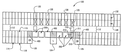
Referring now to the drawings, FIG. 1 illustrates an automated parking garage
100
that incorporates the method and apparatus for distributing and storing
pallets according to
the present invention. As shown, automated parking garage 100 includes six
entry/exit
stations (EES) 200. Each EES 200 is for receiving and releasing vehicles
stored in the
automated parking garage 100. In this particular embodiment, there are
provided three pallet
stacking stations (PSS) 400 that are located near the several EES 200. Of
course, more or
fewer EES 200 and PSS 400 may be employed depending on the actual and
projected
throughput of the garage 100. The one or more PSS 400 are for storing empty
pallets 212,
which pallets are used for supporting vehicles during vehicle storage and
retrieval operations.
The pallet 212 is removed from the PSS 400 and distributed to the EES 200 as
necessary to
accommodate incoming vehicles. The pallet 212 is removed from the EES 200 and
stored in
the PSS 400 as necessary to accommodate outgoing vehicles. Pallets 212 are
transported
between the plurality of EES 200 and PSS 400 using one or more pallet shuttles
(not shown,
but described more fully hereinbelow).
The automated parking garage 100 includes a number levels (or floors) each
including
a plurality of vehicle storage slots 114 for storing vehicles. As shown, each
storage slot 114
comprises an interior storage rack 116 and an exterior storage rack 118 such
that the storage
slot 114 may store up to two vehicles. Thus a first vehicle may be stored in
the interior
storage rack 116 and a second vehicle may be stored in the exterior storage
rack 118. In
addition to the storage available for vehicles shown in FIG. 1, storage for
vehicles is provided
on upper and/or lower floors of the automated parking garage 100. One or more
vertical lift
conveyors (VLC) 120 are provided for transporting vehicles between floors of
the automated
parking garage 100. Note that the disclosed automated parking garage
architecture is
sufficiently flexible to accommodate varying rows of parking, for example, two
rows, three
rows, fours rows, etc.
During storage and retrieval operations, a vehicle is transported on a
supporting pallet
212 between the storage slot 114 and one of the EES 200 using a carrier module
110. The
carrier module 110 accomplishes such transportation via an aisle 112. The
carrier module
110 includes a rack entry module (REM) (described in more detail hereinbelow)
for
transferring the pallet 212 (in an empty or unloaded state, or carrying a
vehicle in a loaded
state) between the carrier module 110 and, the interior and exterior storage
racks (116 and
118), an EES 200, or a VLC 120.
7
CA 02596878 2007-08-03
WO 2006/086348 PCT/US2006/004196
The facilities of the automated parking garage 100, including the VLC 120, the
carrier
module 110, REM, pallet shuttle 250, and pallet vertical lift (PVL) 610 (shown
in greater
detail hereinbelow) are controlled by a central garage computer control
system. The central
computer control system, executing the appropriate system control software, is
preferably
housed in one or more control rooms 126. The automated parking garage 100
further
includes one or more lobbies 124 where a customer may request a vehicle to be
retrieved, and
pay for the automated parking service.
When a vehicle enters the automated parking garage 100, the vehicle enters one
of the
EES 200 through an open exterior door 210 and moves onto the pallet 212, both
of which are
described in greater detail hereinbelow. Before the vehicle enters one of the
EES 200, an
interior door 211 is closed to prevent the vehicle occupants from accessing
the interior of the
automated parking garage 100. The driver and passengers of the vehicle exit
the vehicle and
EES 200, and activate the automated parking process via an automated parking
teller located
just outside of the exterior door 210 of the EES 200, thereby closing the
exterior door 210 of
the EES 200. In response thereto, the carrier module 110 moves along the aisle
112 to a
position corresponding to the EES 200 through which the vehicle entered the
garage 100.
The REM of the carrier module 110 is controlled to remove the loaded pallet
212 from the
EES 200 and retrieve it onto the carrier module 110. The carrier module 110
includes a
turntable mechanism (described in greater detail hereinbelow) that then turns
180 degrees so
that the vehicle can be retrieved to the EES 200 wherein the customer can
drive out of the
EES 200, instead of having to back out. In an alternative garage embodiment,
where one or
more EES 200 are constructed on either side of the aisle 112, the turntable
feature may not be
necessary since the vehicles can now enter an EES 200 on one side of the aisle
112, and exit
via an different EES on the other side. The central computer determines the
availability of a
select one of the plurality empty storage racks (116 or 118) in which to store
the vehicle with
supporting pallet 212. The central computer then directs the carrier module
110 to traverse
the aisle 112 to a position corresponding to the predetermined empty storage
rack (116 or
118) of the storage slot 114.
In the event that the predetermined storage rack (116 or 118) is located on a
different
floor of the garage 100, the carrier module 110 is positioned across from one
of the VLC 120,
and the REM is controlled to transfer the pallet 212 with vehicle to the VLC
120. The VLC
120 transports the pallet 212 with vehicle to the appropriate floor of the
automated parking
garage 100 where both the pallet 212 and vehicle are transferred to another
carrier module
8
CA 02596878 2007-08-03
WO 2006/086348 PCT/US2006/004196
110 on that floor. Once the other carrier module 110 carrying the pallet 212
with vehicle is in
a position corresponding to the predetermined storage rack, e.g., exterior
storage rack 118 on
the floor, the REM is controlled to transfer the pallet 212 with vehicle to
the predetermined
storage rack 118 for storage. One of ordinary skill in the art will understand
that similar steps
may be executed when retrieving the veliicle from the storage rack 118 on
either the
upper/lower or entrance floors.
According to the present invention, the pallets 212 that are not in use (i.e.,
supporting
a stored vehicle) are stored in the PSS 400 by a pallet storage and
distribution system. In
other words, the pallets 212 are distributed from the PSS 400 to a nearby EES
200 only as
necessary to accommodate incoming vehicles. Similarly, when an outgoing
vehicle vacates
its pallet 212, the unloaded pallet 212 may be transferred to the PSS 400 for
storage. The
pallets 212 stored in PSS 400 provide an immediate inventory of empty pallets
for operating
the automated parking garage 100. Additional pallets 212 may be stacked (or
accuinulated)
into pallet bundles in a pallet stack support mechanism (described in greater
detail
hereinbelow) and stored for future use in an otherwise empty parking rack
(e.g., interior rack
116) on upper/lower floors. Such additional pallets 212 may be stored and
retrieved using
either dedicated hardware, or the same hardware used for storing and
retrieving vehicles on
the upper/lower floors. If dedicated hardware is not used, requests for
storing and retrieving
pallet stacks to/from storage racks are preferably processed during a lull in
the operation of
the automated parking garage 100 (such as at 3:00 am) in order to efficiently
utilize the
resources of the automated parking garage 100.
Note that there is a number of VLCs 120 constructed into the garage 100 (six
in this
embodiment) to provide vertical access between the floors, and that the VLCs
120 are
constructed on an interior row 128. Thus there are corresponding VLC storage
racks 130
"behind" the VLCs 120 in an exterior row 132 that can be utilized for storing
a vehicle. In
order to do so, the VCL 120 must be elevated to the level of the VLC storage
rack 130 so that
the carrier module 110 supporting a loaded pallet 212 can insert the loaded
pallet across (or
through) the VLC 120 to the VLC storage rack 130. Of course, for retrieving
the vehicle, the
VCL 120 must be in position at the level of the VLC storage rack 130 from
which the vehicle
is to be retrieved in order for the carrier module 110 to gain access to the
loaded pallet 212
stored in the VLC storage rack 130.
Since the garage 100 is a multi-level building having a plurality of vehicle
storage
racks, each level has an aisle 112 with associated rail system and one or more
carrier modules
9
CA 02596878 2007-08-03
WO 2006/086348 PCT/US2006/004196
110 for traversing the length of the garage 100 at that level. The carrier
modules 110 of any
particular floor operate independently in accordance with instructions from
the garage control
system. There is also overlapping range of the carrier modules 110 of any
given floor as they
traverse the aisle of that floor such that at least two carrier modules 110
can access the same
storage slot 114 and the same VLC 120. Of course, the carrier modules 110 of
the entrance
level also have overlapping range such that any EES 200 can be accessed by at
least two of
the carrier modules 110 of the entrance level.
Referring now to FIG. 2, there is illustrated an isometric representation of
one of the
ESS 200. The EES 200 is a bay located on an entrance floor of the automated
parking garage
100 at grade level or other levels where vehicles enter or exit the garage
100, and having
dimensions similar to a residential single-car garage. Typically, the EES 200
will have a
width of between approximately fourteen and sixteen feet, and a length of
between
approximately twenty and twenty-two feet.
As indicated above, the EES 200 includes the interior door 211 (not shown) for
providing access between the EES 200 and the interior of the automated parking
garage 100.
The EES 200 further includes the exterior door 210 through which an incoming
vehicle may
enter or an outgoing vehicle may exit, the automated parking garage 100. When
entering the
garage 100, the incoming vehicle is positioned on the pallet 212, which pallet
212 forms a
central portion of the floor of EES 200. The incoming vehicle may be
positioned on the
pallet 212 using any number of mechanisms, such as grooves, bumpers, lights
(e.g.,
marquees) and acoustic signals. A passenger walkway 214 is provided on either
side of the
pallet 212 to enable the driver and other passengers of a vehicle to exit the
vehicle and EES
200 of the automated parking garage 100 prior to initiation of the vehicle
storage process.
The pallet 212 is supported by two retractable pallet supports 216. Each
retractable
pallet support 216 includes a track 220 and a track retractor 218. The pallet
212 has a pallet
lip 213 running the length of each side. A portion of the pallet lip 213 for
each side of the
pallet 212 lies on top of the respective track 220. The pallet 212 is
installed into and removed
from the EES 200 using a pallet shuttle 250. The pallet shuttle 250 is
disposed underneath
the EES 200 in a separate runway extending parallel to the aisle 112. The
pallet shuttle 250
includes a pallet shuttle base 252 having motive means for moving the pallet
shuttle 250
between a first position underneath the EES 200, and a second position
underneath the PSS
400 (not shown). The motive means for moving the pallet shuttle 250 may
include wheels, a
track, and/or any other well-known movement mechanisms. The pallet shuttle 250
further
CA 02596878 2007-08-03
WO 2006/086348 PCT/US2006/004196
includes a pallet shuttle support platform 256 for carrying the empty pallet
212, and a pallet
shuttle elevation mechanism 254 for raising and lowering the pallet shuttle
support platform
256 (and any pallet 212 supported thereupon).
When the pallet 212 is distributed to one of the EES 200, the pallet shuttle
250
carrying the pallet 212 is positioned under the appropriate EES 200. The
retractable pallet
support mechanism 216 is then controlled to cause the track retractors 218 to
drive the tracks
220 to a retracted position, thereby allowing the pallet shuttle 250 to
elevate the pallet 212
into the proper position for installation into the EES 200. To complete the
installation of the
pallet 212 into the EES 200, each retractable pallet support mechanism 216
causes the
corresponding track retractors 218 to extend, driving the tracks 220 into a
support position.
Once the tracks 220 are in a support position, the pallet shuttle support
platform 256 is
lowered, causing the pallet 212 to rest onto the tracks 220, and installation
of the pallet 212 is
complete, leaving the pallet shuttle 250 free to be used for other tasks. One
of ordinary skill
in the art will recognize that similar steps may be executed to remove the
pallet 212 from the
EES 200 for storing in the PSS 400.
Reference is now to FIGURES 3A-9 that illustrate the structure and operation
of the
present invention, including the steps performed for storing the pallet 212
that has been
vacated by an outgoing vehicle. Of course, the same structural elements can be
used to
perform steps for distributing the pallet 212 to the EES 220 for an incoming
vehicle.
FIG. 3A illustrates an isometric representation of the EES 200, and the
structure of the
present invention for executing the first steps required for removal of the
pallet 212 from the
EES 200. As shown, the pallet shuttle 250 causes the pallet shuttle elevation
mechanism 254
to raise the pallet shuttle platform 256 into a position supporting the pallet
212. Each
retractable pallet support mechanism 216 then causes the corresponding track
retractor(s) 218
to position the tracks 220 in a retracted position, which clears the pallet
lip 213 on each of the
sides of the pallet 212. The pallet 212 and pallet shuttle support platform
256 are then
lowered by the pallet shuttle elevation mechanism 254 by passing through the
aperture
defmed, in part, by the tracks 220.
FIG. 3B shows the status of the pallet shuttle 250 just after the pallet 212
has been
removed from the EES 200. The pallet shuttle 250 is illustrated with the
pallet shuttle
elevation mechanism 254 in a partially lowered state. Once the pallet shuttle
elevation
mechanism 254 sufficiently lowers the pallet shuttle support platform 256 and
pallet 212, the
11
CA 02596878 2007-08-03
WO 2006/086348 PCT/US2006/004196
pallet shuttle 250 transports the pallet 212 to another part of the parking
garage 100 for
storage.
Referring now to FIG. 4, there is illustrated a broader view isometric
representation of
the EES 200 showing the PSS 400 adjacent to the EES 200. The PSS 400 includes
a pallet
stack support mechanism 410 with pallet latches 411 that provide support for a
stack of
pallets 412 that are suspended over the pallet shuttle 250. The PSS 400 is
used to store the
pallets 212 that may be immediately delivered to EES 200. The PSS 400 further
serves to
store the empty pallets 212 recently removed from the EES 200.
Once the pallet 212 has been removed from the EES 200, as illustrated
hereinabove in
FIG. 3A and FIG. 3B, the pallet shuttle base 252 of the pallet shuttle 250
traverses on a
shuttle rail system carrying the empty pallet 212 and moves into an alignment
position under
the PSS 400. The PSS 400 and the pallet stack 412 are then lowered to a
position where the
empty pallet 212, as supported by the pallet shuttle support platform 256, is
lifted by the
pallet shuttle elevation mechanism 254 into the PSS 400 from below, and
ultimately placed at
the bottom of pallet stack 412. The pallet stack support mechanism 410 is
configured to
permit the pallet 212 to enter the PSS 400 from underneath, and to provide
support for the
pallet 212 and the remaining pallets in pallet stack 412 once all of the
pallets are rested on
pallet support mechanism 410.
Referring now to FIG. 5, there is illustrated the insertion of the pallet 212
into the PSS
400. The pallet shuttle 250 is illustrated with the pallet shuttle support
platform 256 elevated
such that the pallet 212 is lifted under the pallet stack 412 until the pallet
stack support
mechanism 410 with the pallet latches 411 catch the pallet 212 from underneath
and provide
vertical support for pallet stack 412, once the pallet shuttle support
platform 256 is lowered.
The PSS 400 is designed to accommodate a pallet stack 412 of up to ten
pallets. As
necessary, the pallet stack 412 may be removed from PSS 400 by a pallet
vertical lift (PVL)
to an upper/lower floor for medium or long-term storage.
FIGURES 6 through 10 illustrate the structure and steps performed to remove
the
pallet stack 412 for medium or long-term storage. Referring now to FIG. 6,
there is
illustrated a representation of the PSS 400. As shown, the PSS 400 is filled
to capacity with
the pallet stack 412 having ten pallets 212. As further shown in FIG. 6, a PVL
610 is
positioned directly above the PSS 400 for lifting the pallet stack 412. The
PVL 610 includes
a pair of tongs 612 for supporting the weight of pallet stack 412 during
lifting. The PVL 610
12
CA 02596878 2007-08-03
WO 2006/086348 PCT/US2006/004196
further includes a PVL support 614 and PVL motive means 616 for raising and
lowering the
tongs 612.
Referring now to FIG. 7, there is illustrated the PSS 400 of FIG. 4, and the
PVL 610
partially descended with the tongs 612 in an open stance during the removal
process of a
pallet stack 412. The PVL 610 operates to lower the tongs 612 along the sides
of pallets 212
of the pallet stack 412, and after the tongs 612 pass the bottom pallet of the
pallet stack 412,
the PVL 610 closes the tongs 612 and then lifts the pallet bundle 412. The
pallet stacker ten
disengages, to an upper/lower floor for medium or long term storage.
When bringing a pallet bundle 412 to the PSS 400, the PVL 610 is fed a pallet
bundle
412 from equipment of the upper or lower floor. The PVL 610 then lowers the
pallet bundle
412 into the pallet stack support mechanism 410, where the pallet latches 411
engage the
lowest pallet of the pallet bundle 412. The PVL 610 then further lowers a
short distance (e.g.,
1-2 inches), and disengages the tongs 612 to an open stance. Once the PVL 610
elevates
above the pallet bundle 412, the PVL 610 then closes the tongs 612 and rises
to a upper floor
position. The steps are reversed, as indicated in the description hereinbelow,
when removing
a bundle from the PSS 400 to a storage location.
Referring now to FIG. 8, there is illustrated a view of the PVL 610 fully
descended
with the tongs 612 in an open stance.
Referring now to FIG. 9, there is illustrated the PVL 610 in a fully descended
position
with the tongs 612 in a closed position. The tongs 612 are illustrated in a
closed position in
preparation for the PVL 610 rising, and thereby supporting the weight of
pallet stack 412.
The pallet stack 412 is then lifted vertically and removed from PSS 400 for
longer-term
storage in another portion of automated parking garage 100. Once the PVL 610
is in an upper
or lower floor position, secondary parking machinery may be used to retract
the pallet stack
412 from the PVL 610. Such secondary parking machinery may then store the
pallet stack
412 in an empty vehicle storage rack (e.g. storage rack 116). Of course, a
similar process may
be employed to retrieve the stored pallet stack 412 and supply it to the PVL
610.
The PVL 610 lifts the pallet bundle 412 either up or down depending if
utilized in an
underground garage or an above ground garage; in either case the PVL 610 moves
the pallet
bundle 412 to a floor other than the entrance floor (i.e., floor with the EES
220).
Referring now to FIG. 10, there is illustrated the tongs 612 in a closed
stance and the
PVL 610 in a fully ascended position while supporting pallet stack 412.
13
CA 02596878 2007-08-03
WO 2006/086348 PCT/US2006/004196
Referring now to FIG. 11 a, there is illustrated a general diagram of the EES
200, and
the locations of the exterior door 210 and interior door 211 thereof.
Referring now to FIG. 11b, there is illustrated a more detailed view of the
EES 200.
As indicated hereinabove, the EES 200 facilitates entry and exit of a vehicle
of the parking
garage 100. The EES 200 is similar in size to a conventional residential
single-car garage.
The EES 200 includes the exterior door 210 that provides access by a vehicle
to the exterior
of the garage 100 once retrieved, and entry to the garage 100 for parking, and
the interior door
211 (in a cutaway portion) that provides access to the interior of the garage
100. The exterior
and interior doors (210 and 211) can be roll-up doors such that the "up"
position puts either
door on a rail in the ceiling area of the EES 200. In normal operation, only
one door is open
at any point in time.
The EES 200 has a ceiling 1100 that is closed off to preclude exposure to
mechanisms
that may be constructed overhead. Similarly, the EES 200 includes a first
sidewall 1102 and
a second sidewall 1104, both of which are constructed for safety purposes to
prevent exposure
to the mechanisms interior to the garage 100. The floor area 1103 of the EES
200 includes
the pallet 212 and the walkways 214 on either side of the pallet 212 so that
the customer can
exit or enter the vehicle from the walkways 214. The top of the pallet 212 is
positioned
substantially at floor level with the walkways 214 to presenting potential
trip hazards to
customers. As illustrated, the pallet 212 includes a pair of tire guides 1108
into which the
vehicle tires should enter when the vehicle is driven onto the pallet 212.
This helps the
customer determine where to park the vehicle on the pallet 212.
In this particular embodiment, an automated parking teller 1106 is provided
exterior
to the EES 200 that the customer accesses to purchase the parking service, and
to initiate the
parking process. Once the transaction is completed, the customer makes a
selection that
initiates the parking process, causing the exterior door 210 to close. Note
that in an
alternative embodiment, the automated parking teller 1106 can be located
inside of the EES
200 such that once the parking transaction is completed at the teller 1106,
the customer (and
any passengers) must exit the EES 200 prior to the parking process initiating.
In either case,
the interior of the EES 200 can include one or more motion sensors that
prevent initiation of
the automated parking garage mechanisms by the garage control system when
motion is
detected by the presence of the customer and/or passengers in the interior of
the EES 200.
Thus when the customer has paid for the parking service, and the customer and
all passengers
14
CA 02596878 2007-08-03
WO 2006/086348 PCT/US2006/004196
have vacated the EES 200, the motion sensors indicate as such, and the control
system of the
garage 100 then enables the parking procedure for that vehicle.
At the EES 200, the transaction includes either giving a ticket, reading an RF
(radio
frequency) tag (e.g., an EZ pass or similar), or reading a credit card. It is
appreciated that
other conventional transaction methods can also be provided with suitable
accommodations
for processing such transactions. Once the customer returns and wants his car
back, he/she
simply goes to the lobby 124 where a ticket reader, credit card reader, or RF
reader is utilized
to process the corresponding method for clearing payment, thereby initiating
retrieval of the
vehicle. A message center in the lobby 124 will tell the customer where to
pick up the
vehicle (i.e., which of the EES 200 or terminals).
As indicated hereinabove, more robust implementations of the automated parking
teller 1106 can accommodate payment methods that include cash, debit cards,
rechargeable
pre-purchased parking debit cards, or many other conventional means for
completing the
transaction. Additionally, the automated teller 1106, and other automated
tellers associated
with the other EES 200 of the garage 100 are networked to one or more computer
systems
that facilitate the use of the aforementioned payment methods. For example,
where a credit
card is utilized, the teller 1106 must interface to a network that provides
access to the credit
database of the card user so that payment can be properly authorized. Such
access can be
provided via a packet-switched network such as the Internet, by the circuit-
switched network
of the Public Switched Telephone Network, or GPS (global positioning system).
Additionally, the garage 100 can be suitably constructed to provide services
other than
simply parking the car. For example, the customer could, at the time of
accessing the
automated teller 1106, select that his or her vehicle be washed during the
time in which the
vehicle is parked at the garage 100. Thus at some time, a garage attendant
would be made
aware of the purchased service, retrieve the vehicle, wash it, and return the
vehicle to its
parking rack in the garage 100. Other services can also be provided as desired
by the garage
owner, in a more robust implementation of the garage 100 such as performing
routine engine
maintenance to include changing oil, performing a tune-up, car detailing, etc.
Note that the disclosed automated garage 100 can be implemented to accommodate
storage for items other than vehicles. For example, the pallet 212 can be
adapted to
accommodate compatible storage containers such that the containers can be
delivered, stored,
and retrieved utilizing the existing garage equipment and systems.
Additionally, such storage
containers can be constructed for use within the garage 100 without using the
pallet 212.
CA 02596878 2007-08-03
WO 2006/086348 PCT/US2006/004196
Referring now to FIG. 12, there is illustrated a more detailed isometric of
the PSS
assembly 400 that includes the pallet stack support mechanism 410 and PVL 610.
In this
particular embodiment, the PSS 400 is constructed into a multi-floor steel
beam frameworlc
1201 suitable for supporting and lifting the pallet bundle 412. The PSS 400
includes the
pallet stack support mechanism 410 in which pallets are either accumulated
from the EES 200
when vehicles are retrieved for a customer, and removed from the pallet bundle
412 for use in
the EES 200 in preparation to receive a vehicle. The PSS 400 is constructed
over a shuttle
rail system 1200 that accommodates the pallet shuttle 250. The PVL 610 is
suspended from
the framework 1201 such that it can be lowered to either replace or remove the
pallet stack
412 of the pallet stack support mechanism 410. Thus the PVL 610 operates over
the height of
several floors, in accordance with the particular garage design, such that
when the pallet stack
412 is to be handled, the pallet stack 412 can be elevated to and from upper
(or lower floors).
The PSS 400 includes the PVL motor 616 (e.g., an electro-mechanical motor)
that
operates in accordance with control signals from the central control system to
either raise or
lower the PVL 610 by driving a rotating shaft 1204 to take in or let out the
PVL support 614
(i.e., a suspension means).
In operation, the pallet shuttle 250, when receiving control signals from the
control
system computer, traverses the shuttle rail system 1200 in a lateral (or x-
axis) direction 1203
from the EES 200, and is positioned under any of the PSS 400 of the garage
100. The pallet
shuttle 250 includes two pairs of steel shuttle wheels 1207 at each end that
engage the shuttle
rail system 1200. When bringing the pallet 212 to the PSS 400, the control
system signals the
pallet shuttle elevation mechanism 254 (not shown) contained in the pallet
shuttle base 252 of
the pallet shuttle 250 to lift the pallet shuttle support platform 256. The
pallet shuttle support
platform 256 is raised to a point such that the supported pallet 212 on the
pallet shuttle
support platform 256 contacts the lowest pallet of the pallet bundle 412, and
continues rising
forcing the pallet bundle 412 vertically to a height sufficient to allow the
pallet stack support
mechanism 410 to capture the pallet 212 by engaging the support latches 411.
The pallet
shuttle support platform 256 then lowers to a transport position such that the
pallet shuttle
250 can traverse the shuttle rail system 1200 in accordance with instructions
from the garage
control system.
In a scenario where the pallet bundle 412 is removed from the PSS 400 for
storage,
the PVL 610 is controlled to lower about the pallet bundle 412. The tongs 612
are in an open
stance for clearing the pallet bundle 412, and the PVL 610 is lowered to a
point where the top
16
CA 02596878 2007-08-03
WO 2006/086348 PCT/US2006/004196
edge 1206 of the tongs 612 is just lower than the bottom of the lowest pallet
of the pallet
bundle 412. The tongs 612 are then closed and secured for lifting the pallet
bundle 412, after
the pallet stack support mechanism 410 disengages the stack latches 411. The
PVL 610 then
rises to a floor predetermined by the garage control system. When brought into
position at the
designated floor, the PVL 610 is aligned at that floor such that the lower
portion 1208 of the
channel beam of the tongs 612 facilitates insertion of a REM (not shown) for
removal of the
pallet bundle 412 from the PVL 610. An upper carrier module (UCM) assembly
(described in
greater detail hereinbelow) that comprises the REM and UCM accesses the PVL
610 from a
UCM rail system 1210 of that floor.
Referring now to FIG. 13, there is illustrated an end view of the VLC assembly
120.
As indicated hereinabove, the VLC assembly 120 operates to transport only
loaded in the
vertical (or z-axis) direction between the various floors of the garage 100.
The VLC 120 is
constructed within the steel girder structure of the garage 100 so that a
carriage 1300 engages
each of four beams at its corners when reaching the appropriate floor (or
level). As
illustrated, the unloaded carriage 1300 is positioned in a locking mode at a
level of the garage
100 where one end of the carriage 1300 is positioned between two end girders
(1302 and
1304). The carriage 1300 includes an electro-mechanical means 1305 that
operates in
accordance with control signals from the central control system to rotate a
locking shaft 1306
to cause two pairs of opposing locking pins to engage the corner girders.
Here, one pair of
2o pins (1308 and 1310) is illustrated as engaged to respective corner girders
(1302 and 1304).
The electro-mechanical means 1305 connects to another shaft near the other end
f the
carriage 1300 to control locking pins at that end in a similar manner.
In this particular rendition, the VLC 120 is shown with a loaded pallet 212
(i.e.,
supporting a vehicle 1312). Note that the VLC 120 accommodates the loaded
pallet 212 in
the same way the pallet 212 is supported by the retractable pallet support
mechanism 216 of
FIG. 2, that is, by the pallet lips 213. The REM 1314 associated with the
particular floor is
shown inserted into that VLC 120 under the loaded pallet 212 such that the
pallet 212 can be
raised sufficiently to remove the loaded pallet 212 from the VLC 120 (for a
removal
operation). The REM 1314 includes the wheels 1315 for rolling the REM 1314
into the VLC
120 on VLC rails 1316. The carriage 1300 also includes corner assemblies 1318
at each
corner thereof that connect to vertical lifting means (not shown), for
example, chains, so that
the carriage 1300 can be raised or lowered within the vertical shaft of the
VLC 120 defined by
the corner girders.
17
CA 02596878 2007-08-03
WO 2006/086348 PCT/US2006/004196
Referring now to FIG. 14, there is illustrated a more detailed view of the
mechanisms
utilized for retrieving and replacing a pallet, loaded or unloaded, in the EES
200. As
illustrated, the unloaded pallet 212 is resting on the tracks 220 within the
EES 200. The
tracks 220 can be retracted utilizing a number of track retractors 218, which
are electro-
mechanical devices operating under control of the garage control system. That
is, when the
pallet 212 is to be retrieved from or returned to the PSS 400 (not shown), the
track retractors
218 operate to spread the tracks 220 (along the x-axis) sufficiently so that
the pallet 212 can
be lowered downward (in the z-axis) by the pallet shuttle 250. Similarly, when
the pallet 212
is being returned to the EES 200 from the PSS 400, and elevated from below
into position
such that the pallet lips 213 are just above the supporting surface of the
tracks 220, the track
retractors 218 operate to move the tracks 220 inward so that the pallet 212
can be lowered the
short distance thereonto. Note the pallet shuttle 250 travels under the EES
200 on the shuttle
rail system 1200, as indicated hereinabove. Note also that the PSS 400 need
not be adjacent
to the EES 200, since the shuttle rail system 1200 facilitates travel to
virtually any location
along the length of the garage 100.
When a customer has departed the EES 200, and initiated the parking procedure
for a
vehicle, a type of carrier module 110 utilized on the entrance level of the
garage 100, denoted
hereinafter as a lower carrier module (LCM) system 1400, is moved into
alignment with the
EES 200 by the garage control system. The LCM system 1400 includes an LCM
turntable
1402 that rotates 180 degrees in a horizontal plane, a lower carrier 1403
having carrier wheels
1404 on each end that provide for traversing the lengtli of the garage 100 (on
the x-axis) on an
LCM rail system 1406, and a lower rack entry module (REM) 1408 for insertion
into the EES
200 (in the y-axis). Note that the number and orientation of the lower carrier
wheels 1404 are
such that at least one wheel 1404 of a pair is always in a supporting role of
the lower carrier
1403 on the LCM rail system 1406.
The LCM turntable 1402 includes a rail (or wheel guide) 1410 on each side into
which
the wheels 1412 on either side of the lower carrier REM 1408 travel. The lower
carrier REM
rails 1410 of the LCM turntable 1402 are designed to align with a lower inside
L-portion
1414 of the channel beams that function as the tracks 220 that support the
loaded pallet 212 in
the EES 200. The lower inside L-portion 1414 of each track 220 functions as a
rail over
which the wheels 1412 roll in order to position the lower carrier REM 1408
under the pallet
212. Note that the rails 1410 need not be in close proximity or direct contact
with the
corresponding lower inside L-portion 1414, since the REM wheels 1412 are
grouped into
18
CA 02596878 2007-08-03
WO 2006/086348 PCT/US2006/004196
pairs that are suitably spaced in a supporting role. If the loaded pallet 212
is selected for
storage on the current floor, the LCM system 1400 moves to the designated
storage slot 114,
and the REM 1408 extends into either the interior storage rack 116 or fully to
the exterior
storage rack 118 to store the loaded pallet 212.
Alternatively, if the garage control system directs that the loaded pallet 212
is to be
stored on a different floor, the LCM system 1400 and loaded pallet 212 move to
the VLC 120
(not shown) where the loaded pallet 212 is placed into the VLC 120 for
vertical movement to
the other floor.
The lower carrier REM 1408 of the LCM system 1400 includes a lower REM control
means 1416 that communicates with the garage control system to process signals
that control
functions of the lower carrier REM 1408, including movement into and out of
the EES 200
and elevation of an elevating means. The lower REM control means 1416 connects
electrically to a first wheel drive section 1417, which first wheel drive
section 1417 includes
the following general components (that are not illustrated here, but are shown
in greater detail
in FIG. 17): a first drive means, a first transfer means, and a first set of
four wheels 1412 witli
a pair located on each side and near the end of the REM chassis. The lower REM
control
means 1416 also connects electrically to a second wheel drive section 1419,
which second
wheel drive section 1419 includes a second drive means, a second transfer
means, and a
second set of four wheels 1413 with a pair located on each side and near the
opposite end of
the REM chassis. The first and second drive means may be one or more electro-
mechanical
motors that drive the wheels (1412 and 1413) so that the lower carrier REM
1408 moves
along the y-axis into and out of the tracks 220 of the EES 200. The first and
second transfer
means that transfer the drive torque from the first (and second) drive means
to the wheels
1412 (and 1413) can include any combination of conventional equipment such as
shafts,
gears, belts and pulleys, or chains that suitably designed into the lower
carrier REM 1408 to
facilitate such functions.
The lower REM 1408 also includes a lower REM elevator motive means 1418 under
control of the lower REM control means 1416 so that an elevator component (not
shown) of
the lower REM 1408 can be raised to support the loaded or unloaded pallet 212
in the EES
200, and lowered for transport of the pallet and/or vehicle along the LCM rail
system 1406.
The elevator component comprises a platform for mating with the underside of
the pallet 212
to prevent shifting of the pallet 212 during transport. The lower REM elevator
motive means
1418 includes one or more electric motors of sufficient operating parameters
to drive raising
-- 19
CA 02596878 2007-08-03
WO 2006/086348 PCT/US2006/004196
and lowering of the pallet 212 when loaded. The elevator component can include
several
screw jacks, screw actuators, or similar means that connect to the lower REM
elevator motive
means 1418 to facilitate the elevating process of the lower carrier REM 1408.
The lower carrier 1403 also includes a lower carrier control means (not shown)
in
communication with the garage control system, and a lower carrier drive means
(not shown)
both of which facilitate operation thereof along the LCM rail system 1406 to
position the
LCM 1400 in alignment with the tracks 220. Once aligned, the lower carrier REM
1408
moves along the tracks 220 under the pallet 212, and raises the pallet 212
sufficiently to clear
the tracks 220, and exits the EES 200 back onto the LCM 1402 with the pallet
212. Of
course, the lower carrier REM 1408 is of a width that allows it to be elevated
between the
tracks 220 when the tracks are closed in a supporting role, to support the
pallet 212 for
removal from the EES 200. As described, the track retractors 218 need not be
operated when
removing or retrieving a loaded pallet 212 from the EES 200.
Note that LCM assembly 1400 is only operable on the entrance level floor,
while the
UCM assembly operates on any floor other than the entrance level floor. Floors
other than
the entrance level floor have only a fraction of the vehicle-handling load
performed on the
entrance floor. Thus the UCM assembly is more often available to move the
pallet bundle
412 in and out of the PVL 610, and into and out of storage slots on those
floors. The VLC
120 and LCM assembly 1400 preferably are never utilized to handle pallet
bundles 412 or an
empty pallet; these machines should only handle loaded pallets. The UCM
assemblies handle
only a portion of the vehicles depending on the number of floors in the garage
100.
Referring now to FIG. 15, there is illustrated the carrier module 110 utilized
in the
levels of the garage 100 other than the entrance level, and hereinafter
denoted specifically as
an upper carrier module (UCM) assembly 1500. The UCM assembly 1500 includes an
upper
carrier 1502 and an upper carrier REM 1504 (similar to lower carrier REM
1408). The upper
carrier 1502 is similar to the lower carrier 1403 of the LCM system 1400,
except that the
upper carrier 1502 includes upper carrier rails (or wheel guides, similar to
the rails 1410 of
the LCM system 1400) 1506 within which wheels 1508 (similar to the wheels 1412
of the
lower carrier REM 1408 of the LCM system 1400) situated on either side of the
upper carrier
REM 1504 travel to facilitate movement of the upper carrier REM 1504 along the
y-axis.
Thus generally, the only difference between the LCM assembly 1400 and the UCM
assembly
1500 is that the LCM assembly 1400 includes the LCM turntable 1402 with the
rails 1410,
and the UCM assembly 1500 includes the upper carrier 1502 with the rails 1506,
but not
CA 02596878 2007-08-03
WO 2006/086348 PCT/US2006/004196
turntable feature. The UCM system 1500 includes an upper REM control means
1510 and an
upper REM motive means 1512, both of which provide similar functions as the
corresponding
control means 1416 and motive means 1418 of the lower carrier REM 1408.
The upper REM control means 1510 communicates with the garage control system
to
process signals that control functions of the upper carrier REM 1504,
including movement
into and out of the storage slot 114 (extending across the interior storage
rack 116 to the
exterior storage rack 118) and elevation of an elevating means. The upper REM
control
means 1510 connects electrically to a first wheel drive section 1511, which
first wheel drive
section 1511 includes the following general components (that are not
illustrated here, but are
shown in greater detail in FIG. 17): a first drive means, a first transfer
means, and a first set of
four wheels 1508 with a pair located on each side and near the end of the
upper carrier REM
chassis. The upper REM control means 1510 also connects electrically to a
second wheel
drive section 1513, which second wheel drive section 1513 includes a second
drive means, a
second transfer means, and a second set of four wheels 1509 with a pair
located on each side
and near the opposite end of the upper carrier REM chassis. The first and
second drive means
maybe one or more electro-mechanical motors that drive the wheels (1508 and
1509) so that
the upper carrier REM 1504 moves along the y-axis into and out of tracks 1514
of the storage
slot 114. The first and second transfer means that transfer the drive torque
from the first (and
second) drive means to the wheels 1508 (and 1509) can include any combination
of
conventional equipment such as shafts, gears, belts and pulleys, or chains
that suitably
designed into the upper carrier REM 1504 to facilitate such functions.
The upper carrier REM 1504 also includes an upper REM elevator motive means
1512 under control of the upper REM control means 1510 so that an elevator
component (not
shown) of the upper carrier REM 1504 can be raised or lowered while supporting
the loaded
or unloaded pallet 212, and fiuther lowered for transport of the pallet 212
and/or vehicle
along a UCM rail system 1516. The elevator component comprises a platform for
mating
with the underside of the pallet 212 to prevent shifting of the pallet 212
during transport. The
upper carrier REM elevator motive means 1512 includes one or more electric
motors of
sufficient operating parameters to drive the raising and lowering of the
pallet 212 when
loaded. The elevator component can include several screw jacks that connect to
the upper
carrier REM elevator motive means 1512 to facilitate the elevating process of
the upper
carrier REM 1504. The upper carrier 1502 includes similar arrangements, e.g.,
a control box,
drive sets, etc., to move in the x-axis along the aisles of the associated
floors.
21
CA 02596878 2007-08-03
WO 2006/086348 PCT/US2006/004196
In this particular scenario, the unloaded pallet 212 is stored in one of the
many vehicle
storage slots 114 of the upper (or lower) levels of the garage 100. Thus the
storage slot 114
includes the support beams 1514 that are fixed within the garage structure.
Similar to the
LCM system 1400 mentioned hereinabove, the UCM system 1500 operates over the
UCM
rail system 1516 extending essentially the length of the garage 100. Each
level includes a
single UCM rail system 1516 and one or more UCM systems 1500 operating
independently
under control of the garage control system to retrieve or store loaded and
unloaded pallets
212.
In operation, the UCM system 1500 moves into alignment with the storage slot
114
under control of the garage control system. The alignment process is similar
to that of the
LCM system 1400 such that the upper carrier wheel guides 1506 are aligned with
a lower L-
portion 1518 of the corresponding support beams 1514. The upper carrier REM
1504 is then
controlled to move onto the lower L-portion of the support beams 1514 in a
position under
the pallet 212. The carrier module 1502 remains in alignment position while
the upper carrier
REM 1504 elevates to support the pallet 212. The upper carrier REM 1504 is
then controlled
to return onto the upper carrier 1502. Similar to operation of the lower
carrier REM 1408,
upon return, the upper carrier REM 15041owers back to a more stable position
onto the upper
carrier 1502 for transport of the pallet 212 to one of the several VLCs 120.
Referring now to FIG. 16, there is illustrated a more detailed mechanical view
of the
pallet shuttle 250. As indicated hereinabove, the pallet shuttle 250 comprises
the pallet
shuttle base 252, the pallet shuttle elevation mechanism 254, and pallet
shuttle support
platform 256. The pallet shuttle base 252 includes the shuttle wheels 1207 on
each end that
are in rolling contact with the shuttle rail system 1200. The pallet shuttle
elevation
mechanism 254 comprises four mechanical screw actuators (1600, 1602, 1604, and
1606) that
operate from an elevation drive means 1607 that is under the coordinated
control of a shuttle
control means 1608, which shuttle control means 1608 communicates with the
garage control
system at the control room 126 to facilitate operation of the pallet shuttle
250. The pallet
shuttle elevation mechanism 254 elevates between the tracks 220 when in the
EES 200 to
position sufficient to support the unloaded pallet so that the tracks 220 can
be retracted (or
spread apart) by the track retractors 218. When operating with the PSS 400,
the pallet shuttle
elevation mechanism 254 elevates to a position sufficient to support all of
the pallets 212
currently stored in the PSS 400, and where stack latches 411 of the pallet
stack support
22
CA 02596878 2007-08-03
WO 2006/086348 PCT/US2006/004196
mechanism 410 can then move to support a portion of the bottom pallet of the
stack of pallets
412.
The pallet shuttle base 252 includes one or more shuttle drive means 1610
(e.g.,
electric motors) for driving the wheels 1207 to travel along the shuttle rail
system 1200, and
to lock into position the pallet shuttle 250 when vertically aligned under the
EES 200 or any
of the PCC 4001ocations to handle the pallet 212. The drive means 1610 couple
to
corresponding gear boxes 1612 in which transfer equipment resides to couple
the drive means
1610 to the corresponding wheel sets 1207. As indicated hereinabove, such
transfer
equipment can include belts, pulleys, gears, chains, and shafts as used
conventionally with
such equipment.
Referring now to FIG. 17, there is illustrated a more detailed mechanical view
of a
REM 1700 (similar to lower carrier REM 1408 and upper carrier REM 1504). The
REM
1700 includes a first wheel drive section 1702 and a second wheel drive
section 1704. The
first wheel drive section 1702 includes a first wheel drive means 1706 (e.g.,
an electro-
mechanical motor) that operates under control of a REM control means 1708
(similar to
lower carrier control means 1416 and upper carrier control means 1510). The
first wheel
drive means 1706 is mounted to a first transfer means 1710 such that torque
provided
therefrom is transferred to the wheels 1712 associated with the first wheel
drive section 1702.
As indicated hereinabove, such transfer is suitably provided by conventional
mechanisms
such as belts and pulleys, gears, chains and/or shafts.
Similarly, the second wheel drive section 1704 includes a second wlieel drive
means
1714 (e.g., an electro-mechanical motor) that operates under control of the
REM control
means 1708. The second wheel drive means 1714 is mounted to a second transfer
means
1716 such that torque provided therefrom is transferred to the wheels 1718
associated with
the second wheel drive section 1704. Note that the first and second drive
means (1706 and
1714) are operated synchronously by the REM control means 1708. However, it is
appreciated that the first and second drive means (1706 and 1714) may also be
operated
independent of one another, which provides a back-up feature if one of the
drive means (1706
or 1714) should fail.
The REM 1700 also includes an elevator motive means 1720 under control of the
REM control means 1708 so that an elevator component (not shown) can be raised
or lowered
while supporting the loaded or unloaded pallet 212, and further lowered for
transport of the
pallet 212 and/or vehicle. The elevator component comprises a platform for
mating with the
23
CA 02596878 2007-08-03
WO 2006/086348 PCT/US2006/004196
underside of the pallet 212 to prevent shifting of the pallet 212 during
transport. The REM
elevator motive means 1720 includes one or more electric motors of sufficient
operating
parameters to drive the raising and lowering of the pallet 212 when loaded.
The elevator
component can include several screw actuators or similar means located in
elevator gear
boxes (1722 and 1724), and that connect to the REM elevator motive means 1720
to facilitate
the elevating process.
Note that all vehicle storage operations in the storage area of the garage 100
(i.e., the
area of vehicle storage racks) and handling of loaded pallets to and from the
EES, can be
generalized as being accomplished by a transport system, which transport
system includes the
VLC assembly 120, the LCM system 1400, UCM assembly 1500, carrier aisle
systems, etc.,
although the UCM can be used to handle pallet bundles 412, which of course,
are unloaded
pallets. As mentioned hereinabove, the PSS 400 handles only unloaded pallets.
Since the garage 100 includes a number of upper and lower module systems (1400
and
1500) operating independently under control of the garage control system on
various levels, it
is appreciated that communication from the garage control system to the module
systems
(1400 and 1500) is preferably, but not necessarily, wireless to preclude the
need for large
wiring harness and extensive routings of cable suspended throughout the garage
structure.
Thus each module system (1400 and 1500) would communicate wirelessly with the
garage
control system via a unique frequency.
Although this invention has been described in its preferred forms with a
certain degree
of particularity, it is understood that the present disclosure of the
preferred form has been
made only by way of example and numerous changes in the details of
construction and
combination and arrangement of parts may be resorted to without departing from
the spirit
and scope of the invention.
24