Language selection

Search

Patent 2596906 Summary

Third-party information liability

Some of the information on this Web page has been provided by external sources. The Government of Canada is not responsible for the accuracy, reliability or currency of the information supplied by external sources. Users wishing to rely upon this information should consult directly with the source of the information. Content provided by external sources is not subject to official languages, privacy and accessibility requirements.

Claims and Abstract availability

Any discrepancies in the text and image of the Claims and Abstract are due to differing posting times. Text of the Claims and Abstract are posted:

  • At the time the application is open to public inspection;
  • At the time of issue of the patent (grant).
(12) Patent: (11) CA 2596906
(54) English Title: ROTARY SYSTEM FOR SUBMERGED PUMPS
(54) French Title: SYSTEME ROTATIF POUR POMPES IMMERGEES
Status: Granted and Issued
Bibliographic Data
(51) International Patent Classification (IPC):
  • F04B 37/10 (2006.01)
  • F04B 39/00 (2006.01)
  • F04D 25/00 (2006.01)
(72) Inventors :
  • GEREMIA, SILVINO (Brazil)
(73) Owners :
  • HIGRA INDUSTRIAL LTDA
(71) Applicants :
  • HIGRA INDUSTRIAL LTDA (Brazil)
(74) Agent: FASKEN MARTINEAU DUMOULIN LLP
(74) Associate agent:
(45) Issued: 2014-11-25
(22) Filed Date: 2007-08-10
(41) Open to Public Inspection: 2008-03-25
Examination requested: 2012-08-09
Availability of licence: N/A
Dedicated to the Public: N/A
(25) Language of filing: English

Patent Cooperation Treaty (PCT): No

(30) Application Priority Data:
Application No. Country/Territory Date
PI 0604125-6 (Brazil) 2006-09-25

Abstracts

English Abstract

The rotary system (2), object of the present invention, is composed of a motoreducer assembly, which is coupled to a rotating shaft (5), through a pulley transmission system. At the lower part of the rotating shaft (5) the submerged pump (1) will be set.


French Abstract

Le système rotatif (2), objet de la présente invention, est constitué dun ensemble motoréducteur, lequel est couplé à un arbre rotatif (5), par un système de transmission à poulie. À la partie la plus basse de larbre rotatif (5), la pompe submergée (1) est fixée.

Claims

Note: Claims are shown in the official language in which they were submitted.

5
Claims:
1. A submerged pump including a rotary system comprising:
a flotation assembly structured to float on a body of water;
a vertical shaft having an upper end and a lower end, said upper end being
disposed above the flotation assembly and said lower end disposed below the
flotation assembly, in a submerged position;
a submerged pump, including an electric motor and a propeller, said
submerged pump connected to the lower end of the vertical shaft, such that a
longitudinal axis of the submerged pump is orthogonal to the vertical shaft;
a motoreducer assembly, including a drive motor, said motoreducer
assembly connected to the upper end of the vertical shaft;
wherein the submerged pump produces a conical current of liquid in a
position substantially horizontal or oblique and
wherein the motoreducer assembly produces a rotation of the vertical
shaft, consequently, the submerged pump and the conical current of liquid are
rotated about the vertical shaft.
2. A submerged pump as defined in claim 1, and including a transmission
system, including pulleys, wherein the upper end of said vertical shaft is
coupled
to said motoreducer assembly through said transmission system.

Description

Note: Descriptions are shown in the official language in which they were submitted.


CA 02596906 2014-05-09
1
ROTARY SYSTEM FOR SUBMERGED PUMPS
Field of the invention
The present patent application deals with a system of floaters with rotary
support for submerged pumps.
History
Conventional submerged aerators and mixers, as they are also called
submerged pumps, oxygenate liquids in a single direction and orientation, this
way, they
have a zone of action limited by the equipment's position of installation,
where the
referred zone of action is similar to a cone. It is in this zone where the
largest
concentration of oxygenation lies. As a consequence, in the vicinities of the
submerged
pump there will be incorporation zones of low oxygen mixture creating dead
zones.
Having in view this unidirectionality, there will be the need for an
implementation of a
greater number of equipments used in the treatment of effluents.
The current aerators and mixers need a well-planned installation layout so
that the largest zone of action possible may occur.
This way the aerators and mixers currently available in the market do not
permit a rotation of the previously mentioned flow orientation or zone of
action. Now,
the oxygenation index directly depends on the amount of time in which the air
bubbles
formed in the mixture stay in contact with the liquid under treatment and on
the largest
zone of action possible.

CA 02596906 2014-05-09
. .
2
Summary of the invention
The invention presented here intends to solve the current problems of the
state of the technique, by proposing a rotary system for a submerged pump to
oxygenate and mix liquids, said submerged pump, including an electric motor
and a
propeller, being rotated about a vertical shaft by a motoreducer assembly,
increasing
the aeration zone of action.
Brief Description of the Drawings
The invention will be better understood with the aid of the figures that
accompany the present description, where:
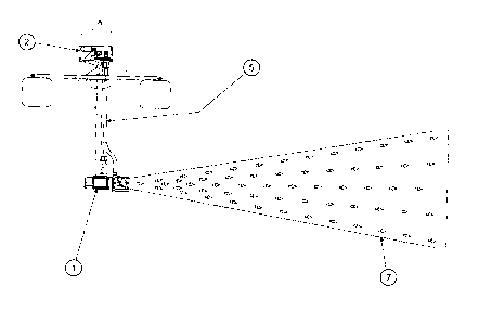
Figure 1 is a side view of the submerged pump 1 where we can observe
the location of the vertical shaft 5 and the conical current of liquid 7;
Figure 2 represents detail A, presented in figure 1, where we observe the
motoreducer assembly 2 and the vertical shaft 5;
Figure 3 is a top view of the submerged pump 1 with the motoreducer
assembly 2, indicating the orientation of rotation 3 and the conical current
of liquid 7;
Figure 4 is a perspective view of the submerged pump 1 with the
motoreducer assembly 2, indicating the orientation of rotation 3;
Figure 5 is a top view of a submerged pump 1 with the conventional
system, where in the conical current of liquid 7, we can observe the limited
effective
area of action;

CA 02596906 2014-05-09
3
Figure 6 is a top view of the submerged pump 1 with the motoreducer
assembly 2, indicating the effective area of action, represented by the
rotation of the
conical current of liquid 7.
Detailed Description of the Embodiment(s) of the Invention
The rotary system for a submerged pump 1, object of the present
invention, comprise a flotation assembly structured to float on a body of
water and a
vertical shaft 5 having an upper end and a lower end, said upper end being
disposed
above of the flotation assembly and said lower end disposed below of the
flotation
assembly, in a submerged position. A submerged pump 1, including an electric
motor
and a propeller, is connected to the lower end of the vertical shaft 5, such
that a
longitudinal axis of the submerged pump 1 is orthogonal to the vertical shaft
5. A
motoreducer assembly 2, including a drive motor, is connected to the upper end
of the
vertical shaft 5. The submerged pump 1 produces a conical current of liquid 7
in a
position substantially horizontal or oblique. The motoreducer assembly 2
produces a
rotation of the vertical shaft 5. Consequently, the submerged pump 1 and the
conical
current of liquid 7 are rotated about the vertical shaft 5.
The rotation of the vertical shaft 5 displaces gradually the conical current
of liquid 7 generated by the propeller of the submerged pump 1, as it can be
seen in a
comparison between figures 5 and 6. The present invention permits the
maximization of
the conical current of liquid 7 of the oxygenation/mixture flow, which will
act in all
directions, reducing the number of aerators and the final consumed power.

CA 02596906 2014-05-09
4
The conical current of liquid 7 is maximized due the rotation of the
submerged pump 1, aerating its entire vicinity and mixing the aerated with non-
aerated
water.
With this 3600 rotation that will be carried out by the vertical shaft 5
moving together with the submerged pump 1, the entire area around the system
will be
completely aerated/mixed.
As it can be observed in figure 6, the area of action is 12 times larger in
the rotary system for submerged pump 1 in relation to the conventional system.
An area
using the rotary system for submerged pump 1 will use approximately one hour
to
generate a complete rotation (360 ) of the submerged pump 1 that will cover an
area
within an estimated radius of action of 30 m. The process of the rotary system
for
submerged pump 1, besides eliminating the number of application points of the
conventional systems, eliminates the so-called dead zones (non-aerated or
mixed
zones), this way there is an improved efficiency and quality.
It must be evident to the experts of the technique that the present
invention can be configured from many other specific ways without moving away
from
the spirit or scope of the invention. Especially, it must be understood that
the invention
can be configured in the described ways.

Representative Drawing
A single figure which represents the drawing illustrating the invention.
Administrative Status

2024-08-01:As part of the Next Generation Patents (NGP) transition, the Canadian Patents Database (CPD) now contains a more detailed Event History, which replicates the Event Log of our new back-office solution.

Please note that "Inactive:" events refers to events no longer in use in our new back-office solution.

For a clearer understanding of the status of the application/patent presented on this page, the site Disclaimer , as well as the definitions for Patent , Event History , Maintenance Fee  and Payment History  should be consulted.

Event History

Description Date
Maintenance Request Received 2024-07-31
Maintenance Fee Payment Determined Compliant 2024-07-31
Change of Address or Method of Correspondence Request Received 2023-03-10
Change of Address or Method of Correspondence Request Received 2022-08-02
Maintenance Request Received 2022-08-02
Inactive: IPC expired 2022-01-01
Common Representative Appointed 2019-10-30
Grant by Issuance 2014-11-25
Inactive: Cover page published 2014-11-24
Pre-grant 2014-09-15
Inactive: Final fee received 2014-09-15
Letter Sent 2014-07-15
Notice of Allowance is Issued 2014-07-15
Inactive: Approved for allowance (AFA) 2014-07-10
Inactive: Q2 passed 2014-07-10
Amendment Received - Voluntary Amendment 2014-05-09
Inactive: S.30(2) Rules - Examiner requisition 2013-11-12
Inactive: Report - No QC 2013-10-29
Letter Sent 2012-08-23
All Requirements for Examination Determined Compliant 2012-08-09
Request for Examination Received 2012-08-09
Request for Examination Requirements Determined Compliant 2012-08-09
Application Published (Open to Public Inspection) 2008-03-25
Inactive: Cover page published 2008-03-24
Inactive: IPC assigned 2008-03-17
Inactive: First IPC assigned 2008-03-17
Inactive: IPC assigned 2008-03-17
Inactive: Office letter 2007-10-09
Application Received - Regular National 2007-09-11
Inactive: Filing certificate - No RFE (English) 2007-09-11
Filing Requirements Determined Compliant 2007-09-11

Abandonment History

There is no abandonment history.

Maintenance Fee

The last payment was received on 2014-05-26

Note : If the full payment has not been received on or before the date indicated, a further fee may be required which may be one of the following

  • the reinstatement fee;
  • the late payment fee; or
  • additional fee to reverse deemed expiry.

Please refer to the CIPO Patent Fees web page to see all current fee amounts.

Owners on Record

Note: Records showing the ownership history in alphabetical order.

Current Owners on Record
HIGRA INDUSTRIAL LTDA
Past Owners on Record
SILVINO GEREMIA
Past Owners that do not appear in the "Owners on Record" listing will appear in other documentation within the application.
Documents

To view selected files, please enter reCAPTCHA code :


To view images, click a link in the Document Description column. To download the documents, select one or more checkboxes in the first column and then click the "Download Selected in PDF format (Zip Archive)" or the "Download Selected as Single PDF" button.

List of published and non-published patent-specific documents on the CPD .

If you have any difficulty accessing content, you can call the Client Service Centre at 1-866-997-1936 or send them an e-mail at CIPO Client Service Centre.


Document
Description 
Date
(yyyy-mm-dd) 
Number of pages   Size of Image (KB) 
Abstract 2007-08-10 1 8
Description 2007-08-10 3 108
Claims 2007-08-10 1 10
Cover Page 2008-03-19 1 24
Description 2014-05-09 4 130
Drawings 2014-05-09 5 72
Claims 2014-05-09 1 29
Representative drawing 2014-07-08 1 7
Cover Page 2014-10-24 1 31
Confirmation of electronic submission 2024-07-31 1 60
Filing Certificate (English) 2007-09-11 1 169
Reminder of maintenance fee due 2009-04-15 1 112
Reminder - Request for Examination 2012-04-11 1 118
Acknowledgement of Request for Examination 2012-08-23 1 175
Commissioner's Notice - Application Found Allowable 2014-07-15 1 161
Maintenance fee payment 2023-07-18 1 26
Maintenance fee payment 2018-08-09 1 26
Correspondence 2007-09-11 1 18
Correspondence 2007-10-03 1 12
Fees 2009-07-24 1 33
Fees 2011-08-09 1 202
Fees 2013-08-06 1 24
Fees 2014-05-26 1 24
Correspondence 2014-09-15 1 35
Fees 2015-07-17 1 26
Fees 2016-08-05 1 25
Maintenance fee payment 2017-08-03 1 26
Maintenance fee payment 2019-08-09 1 26
Maintenance fee payment 2020-07-30 1 26
Maintenance fee payment 2021-07-12 1 26
Change to the Method of Correspondence 2022-08-02 2 43
Maintenance fee payment 2022-08-02 2 43