Sélection de la langue

Search

Sommaire du brevet 2596906 

Énoncé de désistement de responsabilité concernant l'information provenant de tiers

Une partie des informations de ce site Web a été fournie par des sources externes. Le gouvernement du Canada n'assume aucune responsabilité concernant la précision, l'actualité ou la fiabilité des informations fournies par les sources externes. Les utilisateurs qui désirent employer cette information devraient consulter directement la source des informations. Le contenu fourni par les sources externes n'est pas assujetti aux exigences sur les langues officielles, la protection des renseignements personnels et l'accessibilité.

Disponibilité de l'Abrégé et des Revendications

L'apparition de différences dans le texte et l'image des Revendications et de l'Abrégé dépend du moment auquel le document est publié. Les textes des Revendications et de l'Abrégé sont affichés :

  • lorsque la demande peut être examinée par le public;
  • lorsque le brevet est émis (délivrance).
(12) Brevet: (11) CA 2596906
(54) Titre français: SYSTEME ROTATIF POUR POMPES IMMERGEES
(54) Titre anglais: ROTARY SYSTEM FOR SUBMERGED PUMPS
Statut: Accordé et délivré
Données bibliographiques
(51) Classification internationale des brevets (CIB):
  • F04B 37/10 (2006.01)
  • F04B 39/00 (2006.01)
  • F04D 25/00 (2006.01)
(72) Inventeurs :
  • GEREMIA, SILVINO (Brésil)
(73) Titulaires :
  • HIGRA INDUSTRIAL LTDA
(71) Demandeurs :
  • HIGRA INDUSTRIAL LTDA (Brésil)
(74) Agent: FASKEN MARTINEAU DUMOULIN LLP
(74) Co-agent:
(45) Délivré: 2014-11-25
(22) Date de dépôt: 2007-08-10
(41) Mise à la disponibilité du public: 2008-03-25
Requête d'examen: 2012-08-09
Licence disponible: S.O.
Cédé au domaine public: S.O.
(25) Langue des documents déposés: Anglais

Traité de coopération en matière de brevets (PCT): Non

(30) Données de priorité de la demande:
Numéro de la demande Pays / territoire Date
PI 0604125-6 (Brésil) 2006-09-25

Abrégés

Abrégé français

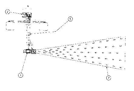
Le système rotatif (2), objet de la présente invention, est constitué dun ensemble motoréducteur, lequel est couplé à un arbre rotatif (5), par un système de transmission à poulie. À la partie la plus basse de larbre rotatif (5), la pompe submergée (1) est fixée.


Abrégé anglais

The rotary system (2), object of the present invention, is composed of a motoreducer assembly, which is coupled to a rotating shaft (5), through a pulley transmission system. At the lower part of the rotating shaft (5) the submerged pump (1) will be set.

Revendications

Note : Les revendications sont présentées dans la langue officielle dans laquelle elles ont été soumises.


5
Claims:
1. A submerged pump including a rotary system comprising:
a flotation assembly structured to float on a body of water;
a vertical shaft having an upper end and a lower end, said upper end being
disposed above the flotation assembly and said lower end disposed below the
flotation assembly, in a submerged position;
a submerged pump, including an electric motor and a propeller, said
submerged pump connected to the lower end of the vertical shaft, such that a
longitudinal axis of the submerged pump is orthogonal to the vertical shaft;
a motoreducer assembly, including a drive motor, said motoreducer
assembly connected to the upper end of the vertical shaft;
wherein the submerged pump produces a conical current of liquid in a
position substantially horizontal or oblique and
wherein the motoreducer assembly produces a rotation of the vertical
shaft, consequently, the submerged pump and the conical current of liquid are
rotated about the vertical shaft.
2. A submerged pump as defined in claim 1, and including a transmission
system, including pulleys, wherein the upper end of said vertical shaft is
coupled
to said motoreducer assembly through said transmission system.

Description

Note : Les descriptions sont présentées dans la langue officielle dans laquelle elles ont été soumises.


CA 02596906 2014-05-09
1
ROTARY SYSTEM FOR SUBMERGED PUMPS
Field of the invention
The present patent application deals with a system of floaters with rotary
support for submerged pumps.
History
Conventional submerged aerators and mixers, as they are also called
submerged pumps, oxygenate liquids in a single direction and orientation, this
way, they
have a zone of action limited by the equipment's position of installation,
where the
referred zone of action is similar to a cone. It is in this zone where the
largest
concentration of oxygenation lies. As a consequence, in the vicinities of the
submerged
pump there will be incorporation zones of low oxygen mixture creating dead
zones.
Having in view this unidirectionality, there will be the need for an
implementation of a
greater number of equipments used in the treatment of effluents.
The current aerators and mixers need a well-planned installation layout so
that the largest zone of action possible may occur.
This way the aerators and mixers currently available in the market do not
permit a rotation of the previously mentioned flow orientation or zone of
action. Now,
the oxygenation index directly depends on the amount of time in which the air
bubbles
formed in the mixture stay in contact with the liquid under treatment and on
the largest
zone of action possible.

CA 02596906 2014-05-09
. .
2
Summary of the invention
The invention presented here intends to solve the current problems of the
state of the technique, by proposing a rotary system for a submerged pump to
oxygenate and mix liquids, said submerged pump, including an electric motor
and a
propeller, being rotated about a vertical shaft by a motoreducer assembly,
increasing
the aeration zone of action.
Brief Description of the Drawings
The invention will be better understood with the aid of the figures that
accompany the present description, where:
Figure 1 is a side view of the submerged pump 1 where we can observe
the location of the vertical shaft 5 and the conical current of liquid 7;
Figure 2 represents detail A, presented in figure 1, where we observe the
motoreducer assembly 2 and the vertical shaft 5;
Figure 3 is a top view of the submerged pump 1 with the motoreducer
assembly 2, indicating the orientation of rotation 3 and the conical current
of liquid 7;
Figure 4 is a perspective view of the submerged pump 1 with the
motoreducer assembly 2, indicating the orientation of rotation 3;
Figure 5 is a top view of a submerged pump 1 with the conventional
system, where in the conical current of liquid 7, we can observe the limited
effective
area of action;

CA 02596906 2014-05-09
3
Figure 6 is a top view of the submerged pump 1 with the motoreducer
assembly 2, indicating the effective area of action, represented by the
rotation of the
conical current of liquid 7.
Detailed Description of the Embodiment(s) of the Invention
The rotary system for a submerged pump 1, object of the present
invention, comprise a flotation assembly structured to float on a body of
water and a
vertical shaft 5 having an upper end and a lower end, said upper end being
disposed
above of the flotation assembly and said lower end disposed below of the
flotation
assembly, in a submerged position. A submerged pump 1, including an electric
motor
and a propeller, is connected to the lower end of the vertical shaft 5, such
that a
longitudinal axis of the submerged pump 1 is orthogonal to the vertical shaft
5. A
motoreducer assembly 2, including a drive motor, is connected to the upper end
of the
vertical shaft 5. The submerged pump 1 produces a conical current of liquid 7
in a
position substantially horizontal or oblique. The motoreducer assembly 2
produces a
rotation of the vertical shaft 5. Consequently, the submerged pump 1 and the
conical
current of liquid 7 are rotated about the vertical shaft 5.
The rotation of the vertical shaft 5 displaces gradually the conical current
of liquid 7 generated by the propeller of the submerged pump 1, as it can be
seen in a
comparison between figures 5 and 6. The present invention permits the
maximization of
the conical current of liquid 7 of the oxygenation/mixture flow, which will
act in all
directions, reducing the number of aerators and the final consumed power.

CA 02596906 2014-05-09
4
The conical current of liquid 7 is maximized due the rotation of the
submerged pump 1, aerating its entire vicinity and mixing the aerated with non-
aerated
water.
With this 3600 rotation that will be carried out by the vertical shaft 5
moving together with the submerged pump 1, the entire area around the system
will be
completely aerated/mixed.
As it can be observed in figure 6, the area of action is 12 times larger in
the rotary system for submerged pump 1 in relation to the conventional system.
An area
using the rotary system for submerged pump 1 will use approximately one hour
to
generate a complete rotation (360 ) of the submerged pump 1 that will cover an
area
within an estimated radius of action of 30 m. The process of the rotary system
for
submerged pump 1, besides eliminating the number of application points of the
conventional systems, eliminates the so-called dead zones (non-aerated or
mixed
zones), this way there is an improved efficiency and quality.
It must be evident to the experts of the technique that the present
invention can be configured from many other specific ways without moving away
from
the spirit or scope of the invention. Especially, it must be understood that
the invention
can be configured in the described ways.

Dessin représentatif
Une figure unique qui représente un dessin illustrant l'invention.
États administratifs

2024-08-01 : Dans le cadre de la transition vers les Brevets de nouvelle génération (BNG), la base de données sur les brevets canadiens (BDBC) contient désormais un Historique d'événement plus détaillé, qui reproduit le Journal des événements de notre nouvelle solution interne.

Veuillez noter que les événements débutant par « Inactive : » se réfèrent à des événements qui ne sont plus utilisés dans notre nouvelle solution interne.

Pour une meilleure compréhension de l'état de la demande ou brevet qui figure sur cette page, la rubrique Mise en garde , et les descriptions de Brevet , Historique d'événement , Taxes périodiques et Historique des paiements devraient être consultées.

Historique d'événement

Description Date
Requête visant le maintien en état reçue 2024-07-31
Paiement d'une taxe pour le maintien en état jugé conforme 2024-07-31
Requête pour le changement d'adresse ou de mode de correspondance reçue 2023-03-10
Requête pour le changement d'adresse ou de mode de correspondance reçue 2022-08-02
Requête visant le maintien en état reçue 2022-08-02
Inactive : CIB expirée 2022-01-01
Représentant commun nommé 2019-10-30
Accordé par délivrance 2014-11-25
Inactive : Page couverture publiée 2014-11-24
Préoctroi 2014-09-15
Inactive : Taxe finale reçue 2014-09-15
Lettre envoyée 2014-07-15
Un avis d'acceptation est envoyé 2014-07-15
Inactive : Approuvée aux fins d'acceptation (AFA) 2014-07-10
Inactive : Q2 réussi 2014-07-10
Modification reçue - modification volontaire 2014-05-09
Inactive : Dem. de l'examinateur par.30(2) Règles 2013-11-12
Inactive : Rapport - Aucun CQ 2013-10-29
Lettre envoyée 2012-08-23
Toutes les exigences pour l'examen - jugée conforme 2012-08-09
Requête d'examen reçue 2012-08-09
Exigences pour une requête d'examen - jugée conforme 2012-08-09
Demande publiée (accessible au public) 2008-03-25
Inactive : Page couverture publiée 2008-03-24
Inactive : CIB attribuée 2008-03-17
Inactive : CIB en 1re position 2008-03-17
Inactive : CIB attribuée 2008-03-17
Inactive : Lettre officielle 2007-10-09
Demande reçue - nationale ordinaire 2007-09-11
Inactive : Certificat de dépôt - Sans RE (Anglais) 2007-09-11
Exigences de dépôt - jugé conforme 2007-09-11

Historique d'abandonnement

Il n'y a pas d'historique d'abandonnement

Taxes périodiques

Le dernier paiement a été reçu le 2014-05-26

Avis : Si le paiement en totalité n'a pas été reçu au plus tard à la date indiquée, une taxe supplémentaire peut être imposée, soit une des taxes suivantes :

  • taxe de rétablissement ;
  • taxe pour paiement en souffrance ; ou
  • taxe additionnelle pour le renversement d'une péremption réputée.

Veuillez vous référer à la page web des taxes sur les brevets de l'OPIC pour voir tous les montants actuels des taxes.

Titulaires au dossier

Les titulaires actuels et antérieures au dossier sont affichés en ordre alphabétique.

Titulaires actuels au dossier
HIGRA INDUSTRIAL LTDA
Titulaires antérieures au dossier
SILVINO GEREMIA
Les propriétaires antérieurs qui ne figurent pas dans la liste des « Propriétaires au dossier » apparaîtront dans d'autres documents au dossier.
Documents

Pour visionner les fichiers sélectionnés, entrer le code reCAPTCHA :


Pour visualiser une image, cliquer sur un lien dans la colonne description du document. Pour télécharger l'image (les images), cliquer l'une ou plusieurs cases à cocher dans la première colonne et ensuite cliquer sur le bouton "Télécharger sélection en format PDF (archive Zip)" ou le bouton "Télécharger sélection (en un fichier PDF fusionné)".

Liste des documents de brevet publiés et non publiés sur la BDBC .

Si vous avez des difficultés à accéder au contenu, veuillez communiquer avec le Centre de services à la clientèle au 1-866-997-1936, ou envoyer un courriel au Centre de service à la clientèle de l'OPIC.


Description du
Document 
Date
(aaaa-mm-jj) 
Nombre de pages   Taille de l'image (Ko) 
Abrégé 2007-08-10 1 8
Description 2007-08-10 3 108
Revendications 2007-08-10 1 10
Page couverture 2008-03-19 1 24
Description 2014-05-09 4 130
Dessins 2014-05-09 5 72
Revendications 2014-05-09 1 29
Dessin représentatif 2014-07-08 1 7
Page couverture 2014-10-24 1 31
Confirmation de soumission électronique 2024-07-31 1 60
Certificat de dépôt (anglais) 2007-09-11 1 169
Rappel de taxe de maintien due 2009-04-15 1 112
Rappel - requête d'examen 2012-04-11 1 118
Accusé de réception de la requête d'examen 2012-08-23 1 175
Avis du commissaire - Demande jugée acceptable 2014-07-15 1 161
Paiement de taxe périodique 2023-07-18 1 26
Paiement de taxe périodique 2018-08-09 1 26
Correspondance 2007-09-11 1 18
Correspondance 2007-10-03 1 12
Taxes 2009-07-24 1 33
Taxes 2011-08-09 1 202
Taxes 2013-08-06 1 24
Taxes 2014-05-26 1 24
Correspondance 2014-09-15 1 35
Taxes 2015-07-17 1 26
Taxes 2016-08-05 1 25
Paiement de taxe périodique 2017-08-03 1 26
Paiement de taxe périodique 2019-08-09 1 26
Paiement de taxe périodique 2020-07-30 1 26
Paiement de taxe périodique 2021-07-12 1 26
Changement à la méthode de correspondance 2022-08-02 2 43
Paiement de taxe périodique 2022-08-02 2 43