Note: Descriptions are shown in the official language in which they were submitted.
CA 02597185 2007-08-02
WO 2006/084192 PCT/US2006/003965
PULSE GENERATOR FOR A CONTROLLED RECTIFIER
CROSS REFERENCE TO RELATED APPLICATION
This application claims the benefit of U.S. Provisional Application No.
60/649,720, filed
February 2, 2005.
TECHNICAL FIELD OF THE INVENTION
The present invention relates to voltage and current control systems for
machines for
converting between mechanical and electrical energy, such as brushless AC
generators, and in
particular to a control system for a compact permanent magnet high power
alternator, such as a
compact permanent magnet high power alternator suitable for automotive use.
BACKGROUND OF THE INVENTION
An alternator typically comprises a rotor mounted on a rotating shaft and
disposed
concentrically relative to a stationary stator. The rotor is typically
disposed within the stator.
However, the stator may be alternatively positioned concentrically within the
rotor. An external
energy source, such as a motor or turbine, commonly drives the rotating
element, directly or
through an intermediate system such as a pulley belt. Both the stator and the
rotor have a series
of poles. Either the rotor or the stator generates a magnetic field, which
interacts with windings
on the poles of the other structure. As the magnetic field intercepts the
windings, an electric field
is generated, which is provided to a suitable load. The induced electric field
(which is commonly
known as a voltage source) is typically applied to a rectifier, sometimes
regulated, and provided
as a DC output power source. The induced current is typically applied to a
rectifier, sometimes
regulated, and provided as a DC output power source. In some instances, a
regulated DC output
signal is applied to a DC to AC inverter to provide an AC output.
Conventionally, alternators employed in motor vehicle applications typically
comprise: a
housing, mounted on the exterior of an engine; a stator having 3-phase
windings housed in the
housing, a belt-driven claw-pole type (e.g. Lundell) rotor rotatably supported
in the housing
within the stator. However, to increase power output the size of the
conventional alternator must
be significantly increased. Accordingly, space constraints in vehicles tend to
make such
alternators difficult to use in high output, e.g. 5 KW, applications, such as
for powering air
conditioning, refrigeration, or communications apparatus.
In addition, the claw-pole type rotors, carrying windings, are relatively
heavy (often
comprising as much as three quarters of the total weight of the alternator)
and create substantial
inertia. Such inertia, in effect, presents a load on the engine each time the
engine is accelerated.
This tends to decrease the efficiency of the engine, causing additional fuel
consumption. In
1
CA 02597185 2007-08-02
WO 2006/084192 PCT/US2006/003965
addition, such inertia can be problematical in applications such as electrical
or hybrid vehicles.
Hybrid vehicles utilize a gasoline engine to propel the vehicle at speeds
above a predetermined
threshold, e.g. 30 Kph (typically corresponding to a range of RPM where the
gasoline engine is
most efficient). Similarly, in a so-called "mild hybrid," a starter-generator
is employed to provide
an initial burst of propulsion when the driver depresses the accelerator
pedal, facilitating shutting
off the vehicle engine when the vehicle is stopped in traffic to save fuel and
cut down on
emissions. Such mild hybrid systems typically contemplate use of a high-
voltage (e.g. 42 volts)
electrical system. The alternator in such systems must be capable of
recharging the battery to
sufficient levels to drive the starter-generator to provide the initial burst
of propulsion between
successive stops, particularly in stop and go traffic. Thus, a relatively high
power, low inertia
alternator is needed.
In general, there is in need for additional electrical power for powering
control and drive
systems, air conditioning and appliances in vehicles. This is particularly
true of vehicles for
recreational, industrial transport applications such as refrigeration,
construction applications, and
military applications.
For example, there is a trend in the motor vehicle industry to employ
intelligent electrical,
rather than mechanical or hydraulic control and drive systems to decrease the
power load on the
vehicle engine and increased fuel economy. Such systems may be employed, for
example, in
connection with steering servos (which typically are active only a steering
correction is
required), shock absorbers (using feedback to adjust the stiffness of the
shock absorbers to road
and speed conditions), and air conditioning (operating the compressor at the
minimum speed
required to maintain constant temperature). The use of such electrical control
and drive systems
tends to increase the demand on the electrical power system of the vehicle.
Similarly, it is desirable that mobile refrigeration systems be electrically
driven. For
example, driving the refrigeration system at variable speeds (independently of
the vehicle engine
rpm) can increase efficiency. In addition, with electrically driven systems
the hoses connecting
the various components, e.g. the compressor (on the engine), condenser
(disposed to be exposed
to air), and evaporation unit (located in the cold compartment), can be
replaced by an electrically
driven hermetically sealed system analogous to a home refrigerator or air-
conditioner.
Accordingly, it is desirable that a vehicle electrical power system in such
application be capable
of providing the requisite power levels for an electrically driven unit.
There is also a particular need for a "remove and replace" high power
alternator to retrofit
existing vehicles. Typically only a limited amount of space is provided within
the engine
compartment of the vehicle to accommodate the alternator. Unless a replacement
alternator fits
2
CA 02597185 2007-08-02
WO 2006/084192 PCT/US2006/003965
within that available space, installation is, if possible, significantly
complicated, typically
requiring removal of major components such as radiators, bumpers, etc. and
installation of extra
brackets, belts and hardware. Accordingly, it is desirable that a replacement
alternator fit within
the original space provided, and interfaces with the original hardware.
In general, permanent magnet alternators are well known. Such alternators use
permanent
magnets to generate the requisite magnetic field. Permanent magnet generators
tend to be much
lighter and smaller than traditional wound field generators. Examples of
permanent magnet
alternators are described in US Patents 5,625,276 issued to Scott et al on
Apri129, 1997;
5,705,917 issued to Scott et al on January 6, 1998; 5,886,504 issued to Scott
et al on March 23,
1999; 5,92,611 issued to Scott et al on July 27 1999; 6,034,511 issued to
Scott et al on March 7,
2000; and 6,441,522 issued to Scott on August 27, 2002.
Particularly light and compact permanent magnet alternators can be implemented
by
employing an "external" permanent magnet rotor and an "internal" stator. The
rotor comprises a
hollow cylindrical casing with high-energy permanent magnets disposed on the
interior surface
of the cylinder. The stator is disposed concentrically within the rotor
casing, and suitably
comprises a soft magnetic core, and conductive windings. The core is generally
cylindrical width
an axially crenellated outer peripheral surface with a predetermined number of
equally spaced
teeth and slots. The conductive windings (formed of a suitably insulated
electrical conductor,
such as varnished copper motor wire), are wound through a respective slot,
outwardly along the
side face of the core around a predetermined number of teeth, then back
through another slot.
The portion of the windings extending outside of the crenellation slots along
the side faces of the
core are referred to herein as end turns. Rotation of the rotor about the
stator causes magnetic
flux from the rotor magnets to interact with and induce current in the stator
windings. An
example of such an alternator is described in, for example, the aforementioned
US Patents
5,705,917 issued to Scott et al on January 6, 1998 and 5,92,611 issued to
Scott et al on July 27
1999.
The power supplied by a permanent magnet generator varies significantly
according to
the speed of the rotor. In many applications, changes in the rotor speed are
common due to, for
example, engine speed variations in an automobile, or changes in load
characteristics.
Accordingly, an electronic control system is typically employed. An example of
a permanent
magnet alternator and control system therefore is described in the
aforementioned US Patent
5,625,276 issued to Scott et al on April 29, 1997. Examples of other control
systems are
described in US patent 6,018,200 issued to Anderson, et al. on January 25,
2000. Other
examples of control systems are described in commonly owned co-pending U.S.
Patent
3
CA 02597185 2007-08-02
WO 2006/084192 PCT/US2006/003965
Application No. 10/860,393 by Quazi et al, entitled "Controller For Permanent
Magnet
Alternator" and filed on June 6, 2004. The aforementioned Quazi et al
application is hereby
incorporated by reference as if set forth verbatim herein.
The need to accommodate a wide range of rotor speeds is particularly acute in
motor
vehicle applications. For example, large diesel truck engines typically
operate from 600 RPM at
idle, to 2600 RPM at highway speeds, with occasional bursts to 3000 RPM, when
the engine is
used to retard the speed of the truck. Thus the alternator system is subject
to a 5:1 variation in
RPM. Light duty diesels operate over a somewhat wider range, e.g. from 600 to
4,000 RPM.
Alternators used with gasoline vehicle engines typically must accommodate a
still wider range of
.0 RPM, e.g. from 600 to 6500 RPM. In addition, the alternator must
accommodate variations in
load, i.e., no load to full load. Thus the output voltage of a permanent
magnet alternator used
with gasoline vehicle engines can be subject to a 12:1 variation. Accordingly,
if a conventional
permanent magnet alternator is required to provide operating voltage (e.g. 12
volts) while at idle
with a given load, it will provide multiples of the operating voltage, e.g.
ten (10) times that
voltage, at full engine RPM with that load, e.g. 120 volts. Where the voltage
at idle is 120 V, e.g.
for electric drive air conditioning, or communications apparatus, the voltage
at full engine RPM
would be, e.g. 1200 volts. Such voltage levels are difficult and, indeed,
dangerous to handle. In
addition, such extreme variations in the voltage and current may require more
expensive
components; components rated for the high voltages and currents produced at
high engine RPM
(e.g. highway speeds) are considerably more expensive, than components rated
for more
moderate voltages.
Various attempts to accommodate the wide range of output voltages from
permanent
magnet alternators have been made. For example, the aforementioned Scott et al
US Patent
5,625,276, describes a controller that selectively activates individual
windings to achieve a
desired output. The windings may be connected in a fully parallel
configuration to provide high
current at relatively low voltage levels, or in series to provide high voltage
capacity. As drive
RPM increases, individual windings are, in effect, disconnected from the
operative circuit to
control output voltage and/or current. However, particularly in compact high
power, high speed
ratio applications such as motor vehicles, the switching transitions between
windings have
deleterious effects, especially at the high end of the RPM range.
Other attempts have involved controlling the RPM of the alternator, and thus
its voltage,
independently of the engine RPM. An example of such an attempt is described in
US patent
4,695,776, issued September 22, 1987 to Dishner. These solutions tend to
involve mechanical
components that are large, require maintenance and are subject to wear.
4
CA 02597185 2007-08-02
WO 2006/084192 PCT/US2006/003965
Other attempts have involved diverting a portion of the magnetic flux
generated in the
alternator to modulate output voltage. An example of a system is described in
US patent
4,885,493 issued to Gokhale on December 5, 1989. Flux diversion, however,
typically requires
additional mechanical components and can be slow to react.
Rectification and regulation can be effected as a single process using a
switching bridge
(e.g. SCR bridge) with phase angle control of duty cycle. The bridge includes
respective control
switching devices (e.g. SCRs) that are selectively actuated to provide
conduction paths between
the input and output of the bridge. In essence, each half cycle (irrespective
of polarity) of the AC
signal produces a pulse of a predetermined polarity (typically positive) at
the output of the
bridge. The duration and timing of the conduction perhaps controls the output
of the bridge.
Such switching bridges may be "half controlled", comprising a respective
controlled switching
device (e.g. SCR) and diode for each phase, or "full controlled", comprising
for each phase two
switching devices (e.g. SCRs), one for each polarity.
Conventionally, the switching devices in the bridge are actuated in accordance
with
"phase angle control of duty cycle" to provide a predetermined voltage output
level. Trigger
signals to the switching devices are generated by a controller that detects
zero crossings in the
respective phases of the AC signal and generates the trigger signal
accordingly (typically after a
delay nominally corresponding to a predetermined phase angle in the AC signal,
and,
concomitantly with a desired DC output level). More particularly, in a
conventional system,
when a zero crossing is detected in a particular phase, the controller delays
by a time period
corresponding to the desired duty cycle (which, in turn, corresponds to the
desired output voltage
level). The delay is typically engendered by a one-shot or conventional timing
circuit. For
example, a capacitor is charged with current when the voltage across the
capacitor exceeds a
reference voltage, a trigger to the SCR associated with the phase is
generated, and the capacitor
discharged. In response to the trigger signal, the SCR turns on (is rendered
conductive) and
remains on until the current through it goes to zero, at which point it is
rendered nonconductive
until the next trigger signal. The cycle repeated in response to the next zero
crossing of the
appropriate polarity.
In a half controlled system, phase angle control of the output duty cycle is
effected by
selective actuation of the controlled switching devices during their
associated half cycle of the
AC signal; the diode segments of the legs are rendered conductive during the
entire associated
(opposite polarity) half cycle of the phase. The range of output signals that
can be generated
from a given AC signal level (and thus range of input AC signals) is thus
limited, as compared to
a full controlled system.
5
CA 02597185 2007-08-02
WO 2006/084192 PCT/US2006/003965
When full control is provided, the SCRs are each associated with a particular
half cycle
(polarity) of an associated phase. A trigger signal is generated in response
to (e.g. after the phase
delay) the zero crossing beginning the associated half cycle of the phase.
Accordingly,
provisions must be made to differentiate between positive going and negative
going zero
crossings.
When a switching bridge (e.g. SCR bridge) and phase angle control of duty
cycle is used
in conjunction with an AC power source that varies in magnitude and changes
alternating
frequency very rapidly (as in the case of an motor vehicle alternator) the
variations in voltage
output and ripple contents can be particularly significant. This is
particularly true in full
controlled systems. The variations in ripple contents in the output of the
bridge can produce
unacceptable output ripple harmonics and require extensive filtering. For
example, the outputs of
many alternators are not a uniform sinewave. Non-uniformities in amplitude and
duration often
occur between half cycles, and between phases of the AC input signal to the
bridge, and are
reflected in the outputs of the portions (legs) of the bridge circuitry
associated with the respective
phases. Such distortions and non-uniformities in the alternator output can
occur for any of a
number of reasons, such as, for example, variations in the placement of the
winding turns relative
to each other and, in the case of permanent magnet alternators, relative to
the magnets. Further
variations in the outputs of the portions (legs) of the bridge associated with
the respective phases
(due to, e.g. tolerances, temperature, etc) in component values between the
circuitry associated
with the various phases, cyclic change in frequency due to engine cylinder
firing, variations in
the magnetic air gap, variations of the saturation of the stator teeth as the
magnet progresses etc.
In addition, the output of the generator often includes spurious components
(e.g. spikes)
that can be mistaken for zero crossings by the detector circuitry.
Thus, there is a need for a relatively inexpensive and efficient control
system using
relatively rugged semiconductors (such as SCRs) that can accommodate wide
variations in the
frequency and amplitude of an AC source (e.g. alternator), while minimizing
output ripple
harmonics and filtering requirements.
In some applications there may be relatively long lengths of electrical cable
connecting
the output of the converter to the load. For example, the cabling between the
converter and
battery (load) can be sufficient to cause a voltage drop between the converter
and battery
There are also a number of other factors that can affect the operation of
alternator
systems in the. For example, the operation of alternator systems can be
significantly affected,
and sometimes disabled, by the temperature of the system components. There is
a need for an
6
CA 02597185 2007-08-02
WO 2006/084192 PCT/US2006/003965
alternator control including mechanisms for detecting temperatures harmful to
the operation of
the alternator system.
In alternator systems used to charge batteries, battery temperature has a
direct impact on
the optimal battery charging voltage and battery sulfation is a major
contributor to shortened
battery life. There is a need for alternator charging systems (particularly in
motor vehicle
applications) that can dynamically adjust output for optimized charging
voltage and dynamically
handle battery sulfation.
There is a need for an alternator charging system including a mechanism for
intelligent
control, (e.g. microprocessor), providing for example: monitoring electrical
system performance;
providing electrical system protection; and field adjustment of system
operating parameters.
The stator of a conventional high current motor vehicle alternator is
constructed with
conductors of large cross sectional area effectively connected in series.
Several problems can
exist with this winding method. For example: because of the low number of
turns (in some
instances only a single turn) per pole phase coil, it is difficult or
impossible to make a small
change in design output voltage by changing the number of turns of the phase
pole coil; the
large cross sectional area of the conductors make the stator difficult to
wind; and a short circuit
between coils will typically burn out the entire stator and may stall the
alternator, resulting in
possible damage to the drive system or overloading the vehicle engine.
In general, permanent magnet alternators incorporating a predetermined number
of
independent groups of windings, wound through slots about predetermined
numbers of teeth
where the power provided by each group is relatively unaffected by the status
of the other groups
are known. For example, such an alternator is described, together with a
controller therefor, in
US patent 5,900,722 issued to Scott et al. on May 4, 1999. In the alternator
described in patent
5,900,722, the number of groups of windings was equal to an integer fraction
of the number of
poles, and the controller circuit selectively completed current paths to the
individual groups of
windings to achieve a desired output.
However, there remains a need for a compact high power alternator wherein a
desired
output voltage can be achieved by changing the number of terms of the phase
pole coil, that is
relatively easy to wind, and minimizes the consequence of short circuits,
while at the same time
facilitating cooling. There is also a need for a converter that can
accommodate such an
alternator.
SUMMARY OF THE INVENTION
In accordance with various aspects of the present invention, a relatively
inexpensive,
control system is provided that can accommodate the wide variations in the
output of a generator,
7
CA 02597185 2007-08-02
WO 2006/084192 PCT/US2006/003965
such as a permanent magnet alternator, while providing an output with
relatively uniform phase
ripple.
In accordance with one aspect of the present invention, the trigger signal to
a switching
device (e.g. SCR) is initiated in accordance with the time integral of the
voltage (e.g. volt-
seconds) of the corresponding AC phase half cycle. For example, the trigger
signal is generated
when a ramp signal representative of the volt-seconds in the associated AC
signal phase reaches
a predetermined level. In the preferred embodiment, the ramp is generated by
charging a
capacitor with a signal representative of the voltage from the alternator
itself.
In accordance with another aspect of the present invention, the trigger signal
to a
switching device (e.g. SCR) is initiated only in response to zero crossings
occurring within a
predetermined window of time related to (e.g. tracking) the frequency of the
AC signal.
In accordance with another aspect of the present invention, an automatic gain
system is
employed to compensate for component value differences between the respective
channels.
In accordance with another aspect of the present invention the control can
compensate for
losses present in long cable runs between converter and battery or other
similar loses.
Compensation can be effected either by sensing voltage remotely from the
converter, e.g. in the
vicinity of the battery, or locally within the converter.
In accordance with another aspect of the present invention a battery charging
voltage can
be optimized with respect to battery temperature.
In accordance with another aspect of the present invention a mechanism is
provided to
reduce battery plate sulfation.
In accordance with other aspects of the present invention mechanisms are
provided to
monitor various system parameters and to optimize various system parameters in
the field.
In accordance with another aspect of the present invention various system
protection
methods have been implemented.
In accordance with another aspect of the present invention the stator winding
is wound
with a predetermined number of pole phase coils, preferably equal to the
number of magnetic
poles. Each pole phase coil is wound with enough turns to generate the
required output voltage
of the alternator and a fraction of the output current equal to 1 divided by
the number of
magnetic poles. These individual pole phase coils are then connected in
parallel.
In accordance with another aspect of the present invention, a respective
conducting phase
ring corresponding to each output phase is installed within the alternator
with each coil
corresponding to the associated phase electrically connected to the conducting
phase rings to
facilitate cooling and grouping and transmission of output phases to the
control
8
CA 02597185 2007-08-02
WO 2006/084192 PCT/US2006/003965
In accordance with another aspect of the present invention the conducting
phase rings are
held in place by a non-conducting support structure.
In accordance with another aspect of the present invention the conducting
phase rings are
disposed to provide an efficient cooling by exposure to the cooling fluids
e.g. air, passing over
the conducting phase rings.
BRIEF DESCRIPTION OF THE DRAWING
The present invention will hereinafter be described in conjunction with the
figures of the
appended drawing, wherein like designations denote like elements (unless
otherwise specified).
Figure 1 is a block schematic of a system for converting between mechanical
and
electrical energy.
Figure 2A is a block schematic of a controller in accordance with various
aspects of the
present invention.
Figure 2B (collectively, together with Figure 2A, referred to as Figure 2) is
a block
schematic of a single channel within controller 2A in accordance with various
aspects of the
present invention.
Figure 3 is a schematic of a zero crossing detector suitable for use in the
controller of
Figure 2.
Figure 4A is a schematic of a variable ramp generator, trigger generator, and
buffer
suitable for use in the controller of Figure 2A.
Figure 4B is a diagram of the relative timing of waveforms of the various
signals
involved in generation of the SCR trigger signals in the controller of Figure
2A.
Figure 5 is a schematic of a variable ramp generator, trigger generator, and
automatic
gain control circuit suitable for use in the controller of Figure 2A.
Figure 6 is a schematic of an error amp and variable reference voltage source
suitable for
use in the controller of Figure 2A.
Figure 7 is a schematic of a system enable circuit and buffered optocoupler
suitable for
use in the controller of Figure 2A.
Figure 8 is a schematic of a No-Fire detect circuit suitable for use in the
controller of
Figure 2A.
Figure 9A and 9B (collectively referred to as Figure 9) are schematics of
exemplary
condition sensing circuits suitable for use in the controller of Figure 2A.
Figures 10A and lOB (collectively referred to as Figure 10) are simplified
schematics of a
switching bridge suitable for use in conjunction with the controller of Figure
2A.
9
CA 02597185 2007-08-02
WO 2006/084192 PCT/US2006/003965
Figures 11A and 11B (collectively referred to as Figure 11) are simplified
schematics of an
alternative switching bridge suitable for use in conjunction with the
controller of Figure
2A.
Figures 12A -12Z, and Figures 12AA-12AG (collectively referred to as Figure
12) are schematic flowcharts of a microcontroller program for effecting
operation of the
controller of Figure 2A.
Figure 13 is a schematic of a crowbar circuit suitable for use in the
controller of
Figure 2A.
Figure 14 is a schematic of a relay indicator circuit suitable for use in the
controller of Figure 2A.
Figure 15 is a schematic of an auxiliary 12V supply circuit suitable for use
by the
controller of Figure 2A.
Figure 16 is a block schematic of a microcontroller suitable for use in the
controller of Figure 2A.
Figures 17A - 17e are collectively referred to as Figure 17.
Figure 17A is a side view of the exterior of an alternator in accordance with
various aspects of the present invention.
Figure 17B is a sectional view along A-A of the alternator of Figure 17A.
Figure 17C is sectional view of a terminal in the alternator of Figure 17A.
Figure 17D is a simplified sectional view along B-B of the alternator of
Figure
17A showing the relative placement of the conducting phase rings within the
alternator.
Figure 17E is a diagram showing possible variations of a conducting phase
ring.
Figure 18A is a diagram showing an individual pole phase coil.
Figure 18B is a simplified perspective view of the stator core, and the
conducting
phase rings of the alternator of Figure 17A, illustrating the connections
between the conducting
phase rings and respective groups of windings (winding end turns omitted).
Figure 18C is a side view of a stator with respective pole groups of windings
wound thereon.
Figure 18D perspective view of the stator core, and the conducting phase rings
of
the alternator of Figure 17A, illustrating all the connections between the
conducting phase rings
and all the respective groups of windings.(winding end turns omitted).
DETAILED DESCRIPTION OF THE PREFERRED EMBODIMENT
CA 02597185 2007-08-02
WO 2006/084192 PCT/US2006/003965
Referring now to Fig. 1, a system 100 for converting between mechanical and
electrical energy in accordance with various aspects of the present invention
comprises a
controller 110 and a switching bridge112. System 100 suitably cooperates with
a source of AC
power, such as an alternator 102 and a source of mechanical energy (e.g.
drive) 104, e.g. an
engine or turbine, a load 106, such as a motor and, if desired, in energy
storage device 108, such
as a battery, capacitor, or flywheel. If desired, an inverter (sometimes
categorized as comprising
part of load 106) can also be provided to generate an AC signal at a constant
predetermined
frequency and amplitude (e.g. 60 Hz, 120V).
In general, alternator 102 generates AC power in response to mechanical input
from energy source 104. Alternator 102 preferably provides multi-phase (e.g.
three-phase, six-
phase, etc.) AC output signals, e.g. phase A (118), phase B (120), and phase C
(122). Those
output signals are typically unregulated and may vary significantly in
accordance with drive
RPM (source 104).
The AC phase signals from alternator 102 are applied to system 100, preferably
through input fuses 128. System 100 rectifies the AC signal from alternator
102, i.e. converts it
into a DC signal and regulates the voltage of that signal at a predetermined
level, e.g. 28V.
Switching bridge 112 selectively, in response to control signals from
controller 110, provides
conduction paths between the various phases of the AC signal from alternator
102 and a load
106. Exemplary switching bridges 112 are shown in Figure 10 (a classical fully
controlled SCR
bridge) and Figure 11 (an array of independent bridges). Controller 110
selectively generates
control signals to switching bridge 112 to produce a regulated output signal
at a predetermined
voltage. As will be more fully explained later, controller 110 samples the
regulated output either
locally at input 114, or remotely at input 140 and adjusts the signals to
bridge 112 to maintain the
proper output. Additionally, the output current is sensed at input 116 to
further modify the
control signals to bridge 112.
The regulated DC signal Voltage Regulated Output (VRO) is then applied,
suitably through an output fuse 136, to load 106 and energy storage device
108. Load 106 may
be any device that uses power, such as, e.g. lights, motors, heaters,
electrical equipment, power
converters, e.g. inverters or DC-to-DC converters. Energy storage device 108
filters or smoothes
the output of control system 110 (although, in various embodiments, controller
110 may itself
incorporate or otherwise provide adequate filtering).
Additionally, as will be more fully explained later, other outputs, 150, and
160,
are also provided. Also crowbar circuit 142 is provided for system protection.
11
CA 02597185 2007-08-02
WO 2006/084192 PCT/US2006/003965
Alternator 102 may be any suitable device that generates AC power in response
to
mechanical input, such as a brushless AC generator or a permanent magnet
alternator, and
preferably an alternator of the type described in commonly owned co-pending
U.S. Patent
Application No. 10/889,980 by Charles Y. Lafontaine and Harold C. Scott,
entitled "Compact
High Power Alternator" and filed on July 12, 2004. The aforementioned
Lafontaine et al
application is hereby incorporated by reference as if set forth verbatim
herein. As will be further
described, in the preferred embodiment, alternator 102 is of the compact high
power alternator
type, but includes for each pole, a respective group of windings (including at
least one winding
corresponding to each phase) with all of the windings corresponding to a given
phase connected
in parallel. Preferably, the parallel connection between coils corresponding
to the same phase is
effective through a corresponding conducting phase ring 138, and includes
fusible links 124,
disposed between the conducting phase rings 138, and the output terminals 126
of the alternator.
Conducting phase rings are a means to efficiently collect the output of each
individual coil to its
respective conducting phase ring, which is in turn attached to its respective
output terminal. As
the total number of poles increases so too do the number of individual coils.
The conventional
method of gathering coils involves soldering the motor wire to conventionally
insulated motor
lead wire. As the rated output of the alternator increases, a corresponding
increase in the load
carrying capacity of the motor lead wire is also required. The only means
available to meet the
increasing load demand on the lead motor wire is to increase the cumulative
gauge of the wire by
increasing the gauge of a single wire or by using multiple wires in parallel.
The net effect is
increasingly larger and larger cross sectional areas of motor lead wire. When
considering the
total number of coils and their respective end turns along with the lead wire
and its associated
insulation, the resulting stator assembly with conductor and motor lead wire
tied together
insulate the end turns, detrimental to cooling. The resulting assembly also
restricts the only
available airflow over the end turns further reducing cooling. A preferred
embodiment of
alternator 102 will be described in conjunction with Figure 17.
Briefly, alternator 102 suitably comprises a rotor mounted on a rotating shaft
and
disposed concentrically relative to a stationary stator. The stator suitably
includes respective
phase windings, A, B and C connected together at one end (neutral), in a star
configuration. In
operation, the rotator is driven by external energy source 104, either
directly or through an
intermediate system such as a pulley belt. In motor vehicle applications,
alternator 102 is
typically mounted under hood, and belt driven from the vehicle engine.
Relative motion between
rotor and stator causes voltage to be induced in the windings. Alternator 102
is preferably
designed such that it generates a predetermined minimum voltage at idle or a
minimum RPM
12
CA 02597185 2007-08-02
WO 2006/084192 PCT/US2006/003965
under full load conditions. As noted above, in motor vehicle applications,
drive RPM can vary
widely, e.g. from 600 RPM at idle, to 3000 RPM for large diesel trucks 600 to
4,000 RPM for
light duty diesels, and from 600 to 6500 RPM gasoline vehicle engines. In
addition, the
alternator must accommodate variations in load, i.e., no load to full load.
Thus the output
voltage of a permanent magnet alternator 102 when used with a gasoline vehicle
engine can be
subject to a 12:1 variation. Accordingly, if a conventional permanent magnet
alternator is
required to provide operating voltage (e.g. 18 volts) while at idle speeds
with a given load, it will
provide multiples of the operating voltage, e.g. twelve (12) times that
voltage, at ftill engine
RPM with that load, e.g. 216 volts.
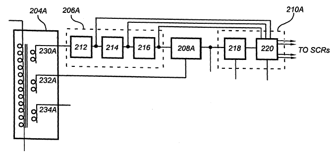
Referring now to Figures 2A, and 2B, controller 110 suitably comprises a
circuitry channel for each phase of the output signal provided by alternator
102. Each circuitry
channel comprises: a respective phase isolation transformer 204 (e.g.
transformers 204A, 204B,
and 204C, respectively, for phases A(118), B(120) and C(122) of a three-phase
AC signal); a
respective zero-crossing detector 206 (e.g. 206A, 206B, and 206C,
respectively, for phases
A(118), B(120) and C(122); a respective variable ramp generator 208 (e.g.
208A, 208B, and
208C, respectively, for phases A(118), B(120) and C(122); and a respective
trigger generator 210
(e.g. 210A, 210B, and 210C, respectively, for phases A(118), B(120), and
C(122)). Referring to
Figure 2B, zero-crossing detectors 206 suitably each comprise a filtered
comparator 212, a
variable blanker 214, and a reset pulse generator 216. Trigger generators 210
suitably each
comprise a comparator 218, and appropriate digital routing logic 220.
Referring to Figure 2, one of the phases (e.g. phase A (118), see also Figure
4) is
designated as a reference phase and includes a suitable buffer amplifier 224
receptive of the
output of variable ramp generator 208. In accordance with one aspect of the
present invention,
the respective circuitry channels associated with other phases (e.g. phases B
(120) and C (122),
see also Figure 5) each include an automatic gain control (AGC) amplifier 222
(e.g. 222B for
phase B (120); 222C for phase C (122)). AGC amplifiers 222 cooperate with the
variable ramp
generator 208 of the associated circuitry channel, are referenced (through
buffer 224) to the
output of the variable ramp generator 208 of the reference channel (e.g.
variable ramp generator
208A), the average voltage value of the ramps generated by variable ramp
generators 208 (e.g.
208A, 208B, and 208C) are made equal by AGC Amplifiers 222(e.g. 222B, and
222C).
Controller 110 suitably further comprises: circuitry, e.g. error amplifier 226
and
variable reference voltage generator 228, for generating a reference signal
indicative of the
desired firing angle to trigger generators 210 (e.g. 210A, 210B, 210C) against
which the output
of the associated variable ramp generator 208 (e.g. 208A, 208B, 208C) is
compared; a
13
CA 02597185 2007-08-02
WO 2006/084192 PCT/US2006/003965
conventional microprocessor or microcontroller 248 (e.g. a PIC18F242) for, in
cooperation with
various other elements of system 100, generating signals indicative of, or to
react to, various
operating conditions, (e.g. controlling various fans in response to system
temperatures, limiting
current or shutting the system down due to over-temperature conditions,
shutting the system
down due to over or under voltage conditions, etc.); an opto enable circuit
250, to selectively
enable and inhibit application of trigger signals to switching bridge 112; a
No-Fire circuit 252 for
generating signals indicative of certain designated conditions during which
application of the
trigger signals to switching bridge 112 are inhibited; a system start circuit
254 for inhibiting
operation in the absence of signals from all phases; a suitable logic power
supply 256; and an
over voltage detect circuit 258.
Referring now to Figure 2B, in general, each of isolation transformers 204 has
a
primary winding driven by the associated phase-to-phase voltage and, multiple,
isolated
secondaries (230A, 230B, and 230C). Zero crossing detectors 206 each examines
one of the
secondaries (e.g. 230A) of the associated transformer 204 and determines when
the voltage
waveform crosses zero.
As previously noted, zero-crossing detectors 206 suitably each comprise a
filtered
comparator 212, a variable blanker 214, and a reset pulse generator 216.
Filtered comparator
212 determines when the voltage is above or below a reference point, e.g. 0
volts to 3.5 volts,
preferably 2.5 volts. The changeover point is deemed to be a potential zero
crossing. Indicia of
the polarity of the signal are provided to the associated trigger generator
210. Variable Blanker
214 provides a blanking pulse equal to a predetermined portion, e.g. between
30% and 70% and
preferably 50%, of the zero crossing-to-zero crossing period so that spurious
zero cross signals
that might be caused by noise following the actual zero crossing, do not
trigger the reset pulse
generator 216. Variable ramp generators 208 each generate a ramp with a shape
characteristic
representing the volt-seconds appearing at the secondaries (232A, 232B, 232C)
of the associated
transformer. The ramp is compared to a ramp reference voltage (RAMP_REF), from
error
amplifier 226. Coincidence at comparator 218 asserts a signal to digital
routing circuit 220 which
generates a trigger signal that turns on the appropriate switching device in
bridge 112. The ramp
is reset by the associated reset pulse generator 216.
More specifically, each of phase isolation transformers 204 (e.g. transformers
204A, 204B, 204C) suitably include a primary winding and multiple (e.g. 3)
secondary windings,
(230, 232 and 234) and generate several isolated, scaled, voltage waveforms
which embody the
characteristics of the associated phase voltage at its respective primary
winding. The primary
winding is driven by the alternator phases A(118)-B (120), B(120)-C (122), or
C(122)-A (118).
14
CA 02597185 2007-08-02
WO 2006/084192 PCT/US2006/003965
The secondary windings provide signals to the associated zero crossing
detector 206 and ramp
generator 208 and to system start circuit 254. Phase isolation transformers
204 are suitably
commercial transformers capable of providing sufficient isolation for the
particular application,
such as, in the preferred embodiment, Tamura 3FS-248 transformers.
A signal indicative of the waveform of the associated phase from one of the
secondary windings (e.g. A (230A), B (230B), or C(230C)) of each transformer
204 is applied to
the associated zero-crossing detector 206 (e.g. 206A, 206B, and 206C). The
zero-crossing
detector 206 detects the occurrence and polarity of voltage zero crossings in
the signal and
generates waveform polarity information and ramp reset signals. The output
signals of each
.0 zero-crossing detector 206 (e.g. 206A, 206B, and 206C) is provided to the
associated variable
ramp generator 208 (e.g. 208A, 208B, and 208C) and trigger generator 210 (e.g.
210A, 210B,
and 210C). The outputs of the trigger generators, if enabled by the
optocoupler enable circuit
250, are applied to fire the SCRs. The optocoupler enable circuit will not
enable the trigger
generator if the INHIBIT signal is asserted by either the microcontroller 248
or No-Fire circuit
252.
As previously noted, zero-crossing detectors 206 suitably each comprise a
filtered
comparator 212, a variable blanker 214, and a reset pulse generator 216.
Referring now to
Figure 3, filtered comparator 212 suitably comprises a low pass pre-filter
308, and a comparator
310 (preferably with a slight DC hysterisis between .1 and .3 volts preferably
.28 volts). Filter
308 effectively removes high-frequency spikes from the AC phase signal from
transformer 204.
Comparator 310 generates a signal indicative of the polarity of the AC phase
signal; transitions
in the output of comparator 310 indicate a zero-crossing. The output of
comparator 310
(indicative of the polarity of and zero crossings in the associated AC phase)
is applied to the
associated variable blanker 214 and provided, at nominal connection point 304,
for application to
the associated trigger generator 210.
Variable blanker 214 (in cooperation with trigger generator 210) effectively
prevents spurious transitions in the comparator output that might otherwise
cause an SCR trigger
signal to be generated from doing so. Transitions occurring within a
predetermined portion of
the comparator half cycle (e.g. within a predetermined number of phase degrees
after a zero-
crossing) are prevented from generating an SCR trigger signal. Still referring
to Figure 3,
variable blanker 214 suitably comprises a monostable multi-vibrator (one shot)
312, a filter 314
and a variable current source 316. One shot 312 is triggered by both positive
going and negative
going transitions in the output of comparator 310. The duration of the pulse
generated by one
shot 312 is a predetermined portion (e.g. suitably in the range of 30% to 70%,
and preferably
CA 02597185 2007-08-02
WO 2006/084192 PCT/US2006/003965
50%) of the time between triggers (transitions in the comparator output),
i.e., the duration of the
half cycle of the output of comparator 310.
In the preferred embodiment, the duration of the one shot output pulse is
controlled by the time required to charge a timing capacitor (e.g. 318). The
timing capacitor is
typically discharged when one shot 312 is triggered, and the output of one
shot 312 is maintained
at a predetermined level (e.g. the Q output of one shot 312 is held high)
until capacitor 318
recharges to a predetermined level (at which point the Q output goes low). In
conventional
applications, a timing capacitor is typically charged through a resistor, and
the duration of the
one shot output pulse is constant. In the preferred embodiment of the present
invention,
however, the timing capacitor is charged through current source 316 driven by
a signal
proportional to the duty cycle of the one shot output (and hence the frequency
of the comparator
output) so that a time required to charge the timing capacitor is inversely
proportional to the duty
cycle of the one shot output. More specifically, the inverted output (Q bar of
one shot 312) is
applied to filter 314 which generates a DC signal proportional to the duty
cycle of the one shot
output to current source 316. Thus if the duty cycle (percentage of the
comparator output half
cycle) of Q output pulse decreases, the current provided to the timing
capacitor will decrease.
With decreased charging current, more time is required to charge the capacitor
to the
predetermined level, and thus increasing the duration of the one shot output
pulse. Conversely, if
the duty cycle of the one shot output signal increases, the current to the
timing capacitor is
increased, hastening the charge of the timing capacitor. The values of the
components of filter
314 are chosen such that the duty cycle of the one shot output is equal to the
predetermined value
at a given comparator output frequency. The net result is that the duty cycle
of the one shot
output signal will self adjust to the predetermined value regardless of the
rate of trigger inputs.
The output of one shot 312 is provided to reset pulse generator 216, and, at
connection point 302,
for application to the associated trigger generator 210.
Reset pulse generator 216, in response to transitions of a predetermined
polarity
(e.g. rising edge), generates a short uniform duration pulse suitable for
application to a switching
element (e.g. a transistor 414, Figure 4) in ramp generator 208 to reset the
ramp (e.g. discharge
capacitor 412, Figure 4). Pulse generator 216 suitably comprises a one shot
320, as shown in
Figure 3, providing the pulse at nominal connection point 306 for application
to the associated
ramp generator 208, and associated trigger generator 210. Since one shot 320
is responsive only
to the rising edge of the variable blanker pulse from one shot 312, the reset
pulse can be
generated only once within the period defined by the variable blanker.
16
CA 02597185 2007-08-02
WO 2006/084192 PCT/US2006/003965
Variable ramp generators 208 (e.g. 208A, 208B, 208C) generate a voltage ramp
indicative of the time integral of the associated phase voltage (volt-
seconds). The ramp is reset
at phase zero crossings. More particularly, variable ramp generators 208 each
generate a
volt/second ramp in response to signal from a second secondary winding (e.g.
232A) of the
associated isolation transformer 204. Ramp generators 208 are reset (and begin
a new ramp)
upon zero crossings in the associated phase, as indicated by a reset signal
from the associated
zero-crossing detector 206 (reset pulse generator 216). The instantaneous
output voltage of ramp
generator 208 is thus indicative of the volt seconds of the associated phase
half cycle. Variable
ramp generators 208 provide the volt/second ramp to the associated trigger
generator 210 (210A,
210B, 210C). As will be further discussed, the associated trigger generator
210, compares the
ramp voltage to a reference voltage, and, unless disabled by optocoupler
enable circuit 250,
generates a SCR trigger signal accordingly (e.g. when the ramp voltage is
equal to the reference
voltage).
In the case of the channel associated with designated reference phase (e.g.
phase
A), the ramp is also applied through buffer amplifier 224 to the respective
AGC Amps 222
(222B, 222C) associated with the other channels. As will be more fully
discussed, to facilitate
automatic gain control certain components (e.g. resistors 410, Figure 4) of
the ramp generator
208 associated with the designated reference phase (e.g. 208A) are preferably
of values relative
to the values of analogous components associated with the other phases such
that the output
ramp of the ramp generator 208 associated with the reference phase is greater
than the ramps
generated by the other channels. An exemplary ramp generator 208 suitable for
use in
association with the designated reference phase (e.g. ramp generator 208A) is
shown in Figure 4.
An exemplary ramp generator 208 suitable for use in association with the other
phases (e.g. ramp
generators 208B, 208C) is shown in Figure 5.
Referring to Figures 4 and 5, ramp generators 208 suitably comprise a
rectifier
bridge 408, a resistance (e.g. resistor or resistance network) 410 cooperating
with a capacitor
412, and a switching device 414 (e.g. a transistor). Rectifier bridge 408
generates a DC signal
(indicative of the voltage magnitude of the associated AC phase) which is
applied through
resistance 410 to charge capacitor 412. Switching device 414 is disposed to
provide a
controllable discharge path for capacitor 412 (e.g. shunted across capacitor
412). Switching
device 414 is rendered conductive in response to the reset pulse (generated at
zero crossings)
from reset pulse generator 216 applied to nominal connection point 306 to
discharge capacitor
412. Capacitor 412 is thus charged by a current indicative of the AC phase
voltage beginning at
17
CA 02597185 2007-08-02
WO 2006/084192 PCT/US2006/003965
the zero crossing initiating the instantaneous half cycle, so that the voltage
across capacitor 412
is indicative of the cumulative volt-seconds of the AC phase during the half
cycle.
Generating the ramp as a function of the voltage of the alternator itself
(e.g. the
volt seconds of the waveform) accommodates a wide range of alternator RPM. The
time integral
of the voltage (volt seconds) generated by a given winding of the alternator
during a half cycle is
constant at any RPM. As alternator RPM (and hence frequency of the signals
provided by
transformer 204) increases, the period the half cycle decreases, but the
voltage of the signal
increases such that volt-seconds of the half cycle remain constant. Thus the
ramp is the same
peak value (total volt seconds) for each half cycle at any rpm.
Ramp generators 208 preferably, also include a compensating filter 416,
corresponding to pre-filter 308 in filtered comparator 212. Pre-filter 308 is
preferably, as
previously mentioned, employed in filtered comparator 212 to eliminate
spurious high frequency
transients in the output of the associated phase isolation transformer 204.
Pre-filter 308 tends to
interject a phase shift into the signal from which the zero crossings, (and
reset pulse) are
generated. It is desirable that reasonable fidelity be maintained between the
generation of the
ramp (e.g. ramp interval) and the reset pulses. Accordingly, filter 416 is
provided to generate an
analogous phase shift in the signal from which the ramp is derived.
Referring again to Figure 2, trigger generators 210 (e.g. 210A, 210B, 210C)
compare the ramp indicative of the volt-seconds of the associated phase (from
the associated
ramp generator 208) applied at nominal connection point 404 to a control
voltage indicative of
the desired firing angle e.g. RAMP_REF, (i.e., a phase angle in the AC signal
corresponding to a
desired duty cycle, and, concomitantly, a desired DC output level). A SCR
trigger signal is
generated at voltage coincidence, and, unless disabled by the optocoupler
enable circuit 250,
routed to the appropriate SCR. An exemplary trigger generator 210 is shown in
Figure 4.
Trigger generators 210 suitably comprise a comparator 218, and appropriate
digital routing logic
220. Comparator 218 generates a signal indicative of when the volt-second ramp
from ramp
generator 208 (provided at nominal connection point 404) exceeds a reference
signal (RAMP_
REF) (provided, in the preferred embodiment, by error amp 226 in cooperation
with reference
voltage generator 228) indicative of the desired firing angle. Digital routing
logic 220, suitably
comprises an RC network 450, respective D-type (e.g. 74HC74) flip-flops, 456
and 458 forced
clock circuitry 464, a nor gate, 452 and exclusive or gate,454 and respective
opto-couplers 460
and 462. Responsive to:
18
CA 02597185 2007-08-02
WO 2006/084192 PCT/US2006/003965
the output of comparator 218 (indicative of when the volt-second ramp from
ramp
generator 208 exceeds the reference signal (RAMP_REF);'
the output of filtered comparator 212 (indicative of the polarity of the
instantaneous half
cycle) provided at nominal connection 304;
the output of variable blanker 214, (indicative of the predetermined portion
of the half
cycle during which transitions in the AC phase are deemed spurious and
ignored)
provided at nominal connection point 302; and
the reset pulse (indicative of zero crossing transitions in the AC phase)
provided at
nominal connection point 306; and
the ENABLE signal from opto enable circuit 250
digital routing circuitry 220, when activated, generates a trigger signal to
the positive or negative
SCR associated with the phase at voltage coincidence between the volt-second
ramp and the
reference signal (RAMP_REF). During normal operation the ramp signal (at
nominal
connection point 404) will exceed reference signal RAMP_REF, such that
comparator 218A
generates an output signal, which is passed through gates 452 and 454 to clock
in data from flip
flop 456 into flip flop 458. The Q BAR output of flip flop 456 is provided to
the microcontroller
as signal ZC_SIG. The output of flip flop 458 is applied to buffered
optocouplers 460 and 462
(shown in more detail in Figure 7). When the output of flip flop 458 changes
state, the
optocouplers are (if enabled) activated, sending a signal to the associated
SCRs to fire.
Optocouplers 460 and 462 are enabled by opto enable circuit 250 in the absence
of an INIIIBIT
signal being asserted by either the microcontroller or No-Fire circuit 252.
Polarity information
held by flip flop 456 is derived from the output of comparator 310 (in zero
cross detector 206)
provided at nominal connection point 304 and is clocked by the variable
blanker signal at point
302 (suitably delayed by RC network 450). In the event that signal 404 never
exceeds
RAMP_REF, no clock signal will be generated. In the event no clocking signal
is generated, at
the time of zero cross (signal 306 RAMP RESET) transistor pair 464 initiates a
forced clock to
flip flop 458 The waveforms of the various signals involved in generation of
the SCR trigger
signals are shown in the timing diagram of Figure 4A. [,
AGC Amps 222B, and 222C compare the average voltage from the ramp
generator 208 associated with the designated reference phase (e.g. 208A) with
the average
voltage from the associated ramp generator (e.g. 208B or 208C) and adjust the
gain of the
19
CA 02597185 2007-08-02
WO 2006/084192 PCT/US2006/003965
associated ramp generator (208B or 208C) so that the output ramp amplitude
matches that of
208A. An exemplary AGC Amp 218 suitable for use in association with the
designated
reference phase (e.g. ramp generators 208B, 208C) is illustrated in Figure 5.
As previously noted, variations in the outputs of the portions (legs) of the
bridge
associated with the respective phases tend to occur due to variations in
component values
between the circuitry associated with the various phases, due to e.g.
tolerances, temperature
differences, winding voltage variation etc. The use of AGC amplifiers 222
provides
compensation for such differences. With reference to Figure 5, AGC amplifiers
222 preferably
comprise: a differential amplifier 502; a variable resistance device 504, such
as, for example, a
4N25 optically coupled isolator; respective filters 501 and 508, and a buffer
506 (analogous to
buffer 224 in Fig. 4). Differential amplifier 502 is receptive of signals
indicative of the time
integral (average) of the volt-second ramp from the channel associated with
designated reference
phase (e.g. the output of ramp generator 208A) and of the time integral
(average) of the output
ramp from the associated channel (e.g. the output of ramp generator 208B or
208C). More
specifically, the signal indicative of the reference phase ramp provided by
buffer 224 (Fig 4) at
nominal connection point 402 is applied to filter 501. Filter 501 generates a
DC signal
representing the time integral (average) of the reference phase volt-second
ramp, which is
applied to one (e.g. the positive) input of differential amplifier 502. The
volt-second ramp from
the associated channel (e.g. the output of ramp generator 208B or 208C) at
nominal connection
point 404 is passed through a buffer 506 and applied to filter 508. Filter 508
generates a DC
signal representing the time integral of the associated phase volt-second
ramp, which is applied
to, the other (e.g. the inverting) input of differential amplifier 502. Use of
the integral of the volt-
second ramps permits comparison notwithstanding the phase angle difference
between phases
(e.g. 120 ). The difference between the integrals of the respective volt-
second ramps, generated
by amplifier 502 is employed to control the resistance of variable resistance
504. Variable
resistance 504 is connected such that this adjustment changes the effective
resistance of
resistance 410 controlling the time constant of capacitor 412 in the
associated ramp generator
208 (208B or 208C) so that the time integral of the associated phase volt-
second ramp (e.g. from
208B or 208C) is identical to the time integral (average) of the reference
phase volt-second ramp
(e.g. from 208A). Thus the effects of variations between analogous components
associated with
the respective phases are minimized.
As previously noted, trigger generators 210 (e.g. 210A, 210B, 210C) generate a
trigger signal to the appropriate SCR when the volt-second ramp indicative of
the associated
phase coincides with a control voltage indicative of the desired firing angle.
The control signal
CA 02597185 2007-08-02
WO 2006/084192 PCT/US2006/003965
can be fixed (constant), or variable, as in, for example, a feedback loop
tending to maintain a
predetermined regulated output voltage. In the preferred embodiment, the
reference signal is
established as part of a control loop. By comparing a fraction of the output
voltage with the
reference voltage from variable reference voltage 228, error amplifier 222
provides a control
voltage which ultimately varies the SCR trigger latency and thus adjusts the
output voltage.
Referring to Figures 1, 2, and 6, the voltage across load 106 is fed back
through
suitable connections to the voltage feedback input (local 114 or remote 140
which will be
explained more fully later) to error amp 226. Error amp 226 generates control
signal
RAMP_REF in accordance with deviation of the feedback signal from a reference
voltage
indicative of the desired output voltage. Error amp 226 preferably comprises a
suitable scaling
amplifier 602, a differential amplifier 604 and a suitable inverter/level
shifter 606. The local
feedback voltage (114) provided by internal connections inside the controller,
or remote
feedback voltage (140) is appropriately scaled by amplifier 602, and the
scaled voltage applied
as one input to differential amplifier 604. Additionally, this signal is
provided to the
microcontroller as V_SENSE. Differential amplifier 604 generates a signal
indicative of
deviations in the scaled feedback signal from a reference voltage (provided in
the preferred
embodiment by a variable reference voltage source 228) indicative of the
desired output voltage.
The difference signal is inverted and level shifted as appropriate by
inverter/level shifter 606,
and applied as the control signal RAMP_REF to trigger generators 210. As will
be more fully
explained later, the RAMP_REF signal is also modulated by an elevated charge
signal applied at
610, a battery temperature signal applied at 608, and a current control
summing amplifier 612
which is responsive to current signal 116, and current foldback signals
FOLD_30 and F LD_60.
Variable reference voltage source 228 provides the reference voltage. The
reference voltage can be fixed (constant) or, as in the preferred embodiment,
dynamically
modulated in accordance with an environmental parameter. For example, in
applications where
relatively long lengths of electrical cable connecting the output of the
converter to the load can
be sufficient to cause a significant voltage drop, the reference voltage can
be modulated to
account for such voltage drop. As current to the load increases (and the
cabling voltage drop
increases), the voltage regulation point is adjusted upward to maintain the
desired regulated
voltage at the load.
In certain applications suitable cabling may be installed between the desired
regulation point, (e.g. battery terminals) and the remote sense input (140).
However, in other
applications (particularly retrofit applications) installation of suitable
voltage sense cabling may
not be practical. To accommodate such adjustments in applications were remote
sense is
21
CA 02597185 2007-08-02
WO 2006/084192 PCT/US2006/003965
impractical, a current sensor (e.g. hall effect device, shunt or similar
device) 116, and variable
reference voltage source 228 comprising parallel potentiometers VR1 and VR2
are employed.
Potentiometers VR1 and VR2 are initially adjusted in a no load (zero current)
condition to
provide a reference voltage indicative of the desired output voltage (e.g. the
wiper of
potentiometer VR1 is set to produce the desired reference voltage with
potentiometer VR2 wiper
set to ground). The system load is then increased and VR2 is adjusted to bring
the voltage at the
load (or battery) back to the desired nominal voltage. Thereafter, in
operation, the current
feedback signal from sensor 116 applied to potentiometer VR2 effectively
modulates the
reference voltage to compensate for resistive drops in the cable so that the
voltage across load
106 is substantially constant irrespective of current flow and voltage drop in
the cable.
Alternatively, remote sense input 140 may be utilized to ensure the voltage at
a regulation sense
point (e.g. battery or sensitive load applications) is maintained, negating
inherent system loses
e.g. long cable lengths. In order to utilize remote sense, suitable cabling
should be installed to
make connections between the regulation point (e.g. battery terminals) and the
remote sense
input (140). Due to the resistance at the input of local sense 114, the remote
sense signal applied
at input 140 will automatically override the local sense input at 114. When
using remote sense,
the wiper of potentiometer VR2 is set to ground. Thereafter, the system will
regulate the VRO to
maintain the desired voltage at the sense point (e.g. battery terminals)
regardless of any losses
between the output and the sense point.
It is desirable to adjust the voltage output setpoint (VRO), to accommodate
changes in battery temperature. As shown in Figure 6, the output of a
temperature sensor
nominally provided to input connection point 608 for generating a signal
indicative of battery
temperature may be included. The output of the battery temperature sensor
applied to nominal
connection point 608 is summed with the output of the input and scaling
amplifier, 602. The
battery temperature therefore controls a feedback signal which adjusts the
amplitude of the
RAMP_RE]F signal thereby modulating the output of switching bridge 112 (VRO)
in accordance
with battery temperature (e.g. approximately lOmV reduction in charging
voltage for every
degree C rise for a lead-acid battery). This will cause the battery charging
voltage to be
optimized according to the battery temperature.
It is further desirable to periodically raise the system charging voltage, VRO
in
order to desulfate the battery plates. To accomplish this, microcontroller 248
periodically asserts
a signal (provided at nominal connection point 610) to reference amplifier
604, resulting in
RAMP_REF being lowered, thereby raising the desired output voltage (VRO).
22
CA 02597185 2007-08-02
WO 2006/084192 PCT/US2006/003965
It is desirable to protect the system circuitry from over current conditions
to
prevent system component failure. Again referring to Figure 6, a conventional
summing
amplifier 612 is provided to sum the output of the current sense monitor 116,
with current limit
signals from microcontroller 248. Microcontroller 248 suitably generates
signals indicative of a
desired current limiting function, i.e. to limit the output current by a
selected a percentage, e.g.
either 30% or 60%, in response to over temperature conditions. Microcontroller
248 will assert a
logic level low signal to the appropriately scaled input of summing amplifier
612 (e.g. either the
30%, FOLD_30, or 60%, FOLD_60, reduction input). The output of summing
amplifier 612 is
in turn summed with the input to inverter/level shift amplifier 606 thereby
modulating the
RAMP_REF signal in order to reduce the VRO setpoint during over-current or
current fold-back
conditions.
In non-12 volt systems, (e.g. a 24 volt system) it may be desirable to provide
a
source of 12 volt power for auxiliary systems. In some 24 volt automotive
applications the
alternator provides a 12 volt signal which controls an alternator warning
indicator typically by
powering a relay connected to a warning lamp. Accordingly, referring briefly
to Figures 1 and
14, a circuit 150 may be included in the system 100 to provide a 12 volt
source suitable for
powering the relay or indicator to provide an indication of system operation
(e.g. system
operating normally). Circuit 150 is activated by RELAY_ENABLE from
microcontroller 248.
In some applications, it may be desirable to provide 12 volt power sufficient
to
operate 12 volt subsystems within system 100, in lieu of or in addition to the
circuit of Figure 14.
Referring now to Figures 1 and 15, a circuit 160 may be included in system 100
to provide a 12
volt source sufficient to derive up to 10 amperes of current from the output
(VRO) of switching
bridge 112. Power supply 160 is enabled by the SYSTEM_START signal from system
start
circuit 254. Alternatively, in motor vehicle applications, a signal from the
vehicle ignition switch
may be used to enable circuit 160.
Neither, either, or both of sources 150 and 160 may be included in system 100
as
application requirements dictate or may be replaced by a source of a different
voltage.
It is desirable to provide various failsafe systems to prevent potential
damage to
components in anomalous operating conditions. As shown in Figure 2, controller
110 suitably
includes various subsystems (e.g. microcontroller 248, system start circuit
254, over voltage
circuit 258, etc.) to effectively disable controller 110 under certain
conditions, such as when an
input from alternator is not detected, control voltage RAMP_REF from error amp
226
approaches or exceeds the volt-second ramp value of the designated reference
phase (from e.g.
variable ramp generator 208A and buffer 224 at nominal connection point 402),
or temperature
23
CA 02597185 2007-08-02
WO 2006/084192 PCT/US2006/003965
limits are exceeded. Such conditions are indicated by generation of an INHIBIT
signal by either
microcontroller 248 or No-Fire circuit 252. Referring to Figures 2A, 4, and 7,
opto enable circuit
250 suitably comprises a conventional switch for applying enabling voltage to
optocouplers 460
and 462 in the absence of application of an INHIBIT signal from
microcontroller 248, or No-Fire
circuit 252 which allows the controller to operate normally. At the onset of
an INHIBIT signal,
circuitry 250 removes the optocoupler ENABLE signal.
An exemplary No-Fire circuit 252 is shown in Figure 8. No-Fire circuit 252
compares reference signal RAMP_REF to the output of buffer 224, indicative of
the voltage-
second ramp generated by the designated reference phase channel (provided at
nominal
connection point 402). A RAMP_REF signal exceeding the buffered ramp signal at
point 402
indicates that error amp 226 is responding to very light or no load condition.
When reference
signal RAMP_REF exceeds the output of buffer 224 (at point 402) then No-Fire
circuit 252
asserts the INHIOBIT signal. This prevents firing of the SCRs until the
RAMP_REF signal lowers
to a point below the output of buffer 224 (at point 402) at which point the
SCRs begin to fire
again.
An exemplary over voltage detect circuit 258 is shown in Figure 9B. Over
voltage
detect circuit 258 monitors the output (VRO) of switching bridge 112 and
produces the
OVER_VOLT signal when VRO exceeds a predetermined voltage value (e.g. VRO +
15%). The
OVER_VOLT signal is passed to microcontroller 248 which in turn responds by
asserting the
INHIBIT signal.
In the preferred embodiment, system start circuit 254 prevents system
operation in
situations where all phases of the AC input from alternator 102 are not
present. Referring to
Figures 2A and 9A, system start circuit 254 receives signals indicative of the
outputs of the
respective phases from a third secondary winding (e.g. 234A, 234B, 234C,
respectively) from
each of isolation transformers 204A, 204B, and 204C and generates a control
signal,
SYSTEM_START, only when all phases are present. Activation of the 5V logic
power supply
256 (Figure 15) is contingent on all 3 isolation transforms 204A 204B and 204C
supplying their
respective nominal outputs indicating the presence of all three phases from
alternator 102. In the
event that any phase should fail, the system will shut down.
To protect against over current conditions (e.g. electrical short) fusible
links 124,
are provided in the phase wiring of alternator 102, input fuses 128 and output
fuse 136 are
provided in control system 100. (e.g. 350 amp fusible links, 350 amp input
phase fuses and 400
amp output fuse for a 350 amp system). In addition, to protect electrical
system components
from over voltage conditions, a shorting crowbar circuit 142 (Figures 1 and
13) is provided at the
24
CA 02597185 2007-08-02
WO 2006/084192 PCT/US2006/003965
voltage regulated output (VRO) of switching bridge 112. Crowbar circuit 142
shorts the output
of system 100 in the event of catastrophic over voltage (e.g. 130% of VRO). In
another
embodiment, the crowbar circuit may be used to turn on all switching bridge
112 SCRs thereby
shorting the output of the alternator. An exemplary crowbar circuit 142 is
shown in Figure 13.
Other sensor circuitry providing signals indicative of other operating
parameters
may also be provided to generate inputs to microcontroller 248 as parameters
relevant to
generation of the INHIBIT signal. For example, referring to Figure 16, signals
from sensor
circuitry (not shown) providing signals indicative of various system
parameters such as, for
example, the temperature of alternator 102, the temperature of a heatsink on
which various
components are mounted, the temperature and current into, or out of, the
battery, the rail voltage
(VRO, the DC voltage to load 106 by sampling the output of the input and
scaling amplifier 602,
e.g. V_SENSE, Figure 6), the output current signal 116 and a buffered signal
from a zero-cross
detector (e.g. ZC_SIG, Figure 4) indicative of the alternator RPM, are applied
as inputs to
microcontroller 248. Responsive to those inputs, microcontroller 248 executes
a program to
generate:
indicia of various operational parameters, and
control signals for various fans (not shown) (e.g. an alternator cooling fan,
a control
system cooling fan) including variable speed fans which may be utilized for
enhanced
longevity
A signal to periodically elevate the output of switching bridge 112 (VRO) to a
level
sufficient to reduce sulfation in the battery by driving sulfur from the
battery plates back
into solution in the electrolyte. This elevated charging voltage may be
asserted in
accordance with calculations of battery capacity based on battery temperature,
voltage,
and rate of discharge while the system is quiescent (e.g. engine off). For
example, the
battery voltage at any given temperature may be compared with a look-up table
of
nominal voltages for the type battery used (e.g. Pb-Pb or Pb-Ca).
Additionally, the rate of
voltage drop for any given current drain on the battery may be calculated to
provide an
indication of battery capacity. The elevated charging voltage signal may then
be asserted
at nominal connection point 610 the next time the system is started.
In addition, based on the above battery capacity calculations, a warning
indicator, (e.g.
dashboard lamp) may be activated to indicate to the operator that the battery
is nearing
CA 02597185 2007-08-02
WO 2006/084192 PCT/US2006/003965
end-of-life, in order to prevent failure in the field. Another indicator may
be activated as
a warning that the battery charge is nearing depletion to the point of being
unable to start
the engine.
Other warning indicators may alert the operator of excessive system
temperatures, (e.g.
alternator temperature, control system temperature) in order that the operator
may reduce
system loads to prevent system shutdown.
Signals to reduce the current output first by 30% (FOLD_30), then by 60%
(FOLD_60),
and finally to shut the system down, (INHIBIT), are provided in response to
elevated
system temperatures.
The INHIBIT signal for application to opto enable circuit 250 to remove the
ENABLE
signal to opto-couplers 460 and 462 (Figures 4 and 7) in digital routing
circuits 220, such
that SCR firing is disabled when the microcontroller 248 detects a system
fault.
A flowchart of the program executed by microcontroller 248 is provided in
Figures 12A -12AG. In general, the program is composed of interrupt initiated
and time
sequenced threads and routines, as follows:
INTERRUPTS
IS R_Extlnt_ 1: OVER- V OLT AGE
This interrupt is the response to detection of an over-voltage condition by
over
voltage detect circuit 258 (Figure 9B) as indicated by signal OVER_VOLT. This
is an
error condition and all inhibits are asserted e.g. microcontroller 248
produces the
INHIBIT signal.
ISR ExtInt 0: ZERO-CROSS
This interrupt is the response to a zero-cross of the alternator phase input
going
through zero volts. A signal indicative of the zero-cross is suitably applied
to the
microcontroller, (ZC_SIG, Figure 4). The period of the zero-cross is monitored
to
indicate engine speed.
ISR Timer 0: ZERO-CROSS TIMER ROLL-OVER
26
CA 02597185 2007-08-02
WO 2006/084192 PCT/US2006/003965
This interrupt is the response to an internal counter, Timer_0, incremented in
accordance with an internal clock and reset upon zero crossings (the zero-
cross counter)
rolling over. This is an error condition indicating that the speed of the
engine is too low.
ISR Timer 2: TIME-BASE
This interrupt is the response to the general system delay. It is a repetitive
event that
maintains delays within the firmware.
THREADS and ROUTINES
UpdatePeriodBuffer
This thread is responsible for buffering each zero-cross period. Each time a
new
period is read, a flag indicating whether the new value is valid is tested, if
set, store a
"full-count". The value is stored in the buffer and the average is calculated.
A flag is set
for the other threads to indicate that the average has been updated.
GetAnaloglnputs
This thread is responsible for sampling all of the analog channels. Each
channel is
acquired through the on-chip Analog-to-Digital converter. The readings are
stored in a
buffer for each channel. The average of each buffer is calculated for use by
other threads.
A flag is set for the other threads to indicate that the averages have been
updated.
TestAnalog
This routine tests if the analog averages have been updated. If so, a series
of
bounds checking is performed for the output of switching bridge 112 (rail
voltage, VRO),
the heatsink temperature and the alternator temperature.
TestVoltage
This routine tests a signal representative of the average rail voltage (VRO)
(e.g.
V_SENSE Figure 6) of the system against a series of limits to declare one of
the
following conditions: too low, normal and too high.
TestAlternatorTemp
27
CA 02597185 2007-08-02
WO 2006/084192 PCT/US2006/003965
This routine tests the average alternator temperature against a series of
limits to
declare one of the following conditions: normal, current limit level 1 (e.g.
FOLD_30),
current limit level 2 (e.g. FOLD_60), and system inhibit.
TestI3eatSinkTemp
This routine tests the average heatsink temperature against a series of limits
to
declare one of the following conditions: normal, current limit level 1 (e.g.
FOLD_30),
current limit level 2 (e.g. FOLD_60) and system inhibit.
TestPeriod
This routine tests the average period of the alternator (as determined by the
period
between successive zero crossings) against a series of limits to declare one
of the
following conditions: too low, normal and too high.
BoostControl
This routine tests the elapsed time against the specified boost start and end
times.
The elevated charging voltage signal applied to nominal connection point 610,
(for
reducing sulfation in the battery) is controlled by this routine
UpdateControls
This routine is responsible for controlling the output of the processor based
on
faults declared from the various tests. This routine is also in control of the
fans for the
heatsink and the alternator.
TestEndStartUp
This routine is responsible for holding the system from running until all
faults are
cleared from the various tests.
Referring now to figure l0A As previously noted, switching bridge 112, in
response to control signals from controller 110, selectively provides
conduction paths between
the various phases of the AC signal from alternator 102 and a load 106.
Controller 110
selectively generates control signals to switching bridge 112 to produce a
regulated output signal
at a predetermined voltage. Figure 10 depicts a conventional 3 phase, fully
controlled SCR
bridge. The salient features of this circuit include:
28
CA 02597185 2007-08-02
WO 2006/084192 PCT/US2006/003965
A 3 wire connection to the (three-phase) alternator. Whether the windings are
joined as a"Delta" or "Wye" as shown here, only 3 output wires are required
for operation.
Alternatively, in the "Wye" alternator configuration, neutral may be exported
from the alternator
depending upon application requirements (e.g. split supply operation).
Conduction to the output requires that 2 SCRs are in conduction. There are
therefore conduction losses due to the voltage drop across 2 SCRs.
Because of the rolling nature (120 degrees apart) of the phase voltages
generated
by the alternator, the correct SCR must be fired in the correct order to
control conduction
properly. Thus, there is only one solution for the order of the SCR triggers
for a given alternator
phase order and alternator rotation direction. The directionality is brought
about by the fact that
if the rotation of the alternator is reversed, so too is the phase order of
the outputs, necessitating
reversal of the SCR trigger timings.
Referring to figure lOB, an alternative bridge may be comprised of single SCRs
paired with diodes. This embodiment results in more ripple in the output, but
has the advantage
of having less heat loss due to the forward voltage of the diodes typically
being less than that of
an SCR.
Figure 1 lA depicts an alternative 3 phase fully controlled SCR bridge.
Significantly, all windings in the alternator are completely separate, with no
common
connections. Further, 4 SCRs are utilized to form an independent full wave
bridge for each
individual winding. Six wires are required to connect the alternator to the
bridge. While seeming
a disadvantage over 3 wires in a conventional 3 phase bridge, higher power
circuits may benefit
by the division of currents into multiple conductors. Such an embodiment of a
fully controlled
SCR bridge has particular utility in connection with embodiments of alternator
102 employing
multiple winding coils connected in parallel.
Figure 11B depicts an alternative 3 phase partially controlled SCR bridge.
Like
the embodiment shown in Figure 11A, the SCR bridge of figure 11B has
particular utility in
connection with alternators having all windings in the alternator completely
separate, with no
common connections. However, 6 diodes are used instead of SCRs such that 2
SCRs and 2
diodes are utilized to form an independent full wave bridge segment for each
individual winding.
The features of this arrangement are:
As in the embodiment of Figure 11A, six wires are required to connect the
alternator to the bridge. Again, while seeming a disadvantage over 3 wires in
a conventional 3
phase bridge, higher power circuits may benefit by the division of currents
into multiple
conductors.
29
CA 02597185 2007-08-02
WO 2006/084192 PCT/US2006/003965
Lower losses due to lower conduction drop. Typically a diode has lower
conduction drop than a SCR. Since only one SCR and one diode are involved in
the current path
to the output, the conduction losses will be lower than for 2 SCRs.
In both figure 11A and 11B, each of the individual full wave bridge segments
function independently. While the trigger signals for each bridge must be
timed correctly to
conduct the required current, the need for timing coordination due to phase
rotation is eliminated.
Thus there is no system-wide requirement to trigger the SCRs in the correct
order. Moreover,
because of this timing independence, the alternator windings may be connected
to any of the
bridges arbitrarily. Further, the polarity of connection between an individual
winding and each
l0 bridge may be arbitrary as well, since both SCRs within each bridge may be
triggered
simultaneously and only the device with the proper polarity for conduction
will do so. This
eases installation complexity and avoids connection errors. Further, the
alternator may rotate in
either direction without reassigning the SCR triggers.
It should be noted that the control circuitry previously disclosed for
conventional
3 phase controlled bridges, will control the alternative configuration of
figure 11B, without any
modification. Most of the differences is in lifting the restrictions as to
which winding is
associated with which bridge connection to assure proper operation, and the
lifting of the
alternator rotation direction restrictions, etc.
Referring now to Figure 16, the general form of microcontroller 248 has many
inputs and outputs. Inputs and outputs can be analog or digital, and reflect
communications to
external stand-alone computing apparatus, interface to off-chip support
devices, or interface to
off-board hardware. Examples of analog inputs include, for example signals
indicative of
temperatures, voltages, and current. Examples of temperatures measured are
alternator, heat
sink, battery and ambient. Examples of voltage sense are VRO and the voltage
at energy storage
device (e.g. battery) 108. Examples of current are controller output current
(CUR_SIG) and
battery current. Analog output examples include variable current limit and
variable voltage
boost level. Example digital inputs include over-voltage (OVER_VOLT) from 258,
zero-cross
(ZC_SIG) from 214, alternator fan tachometer, heat sink fan tachometer to
ensure that the fans
are not stalled (e.g. water fording operations). Example digital outputs
include fixed current
limit (e.g. FOLD_60), fixed voltage boost, heat sink fan control, inhibit of
SCR firing, relay
output circuit enable, control of several on-board indicators such as: speed
error, voltage error,
alternator temperature conditions, heat sink temperature conditions,
alternator fan control, heat
sink fan control. Examples of alternator speed errors are low speed (e.g.
engine cranking but not
yet started), and high speed (e.g. engine over-speed). Example VRO voltage
errors are low
CA 02597185 2007-08-02
WO 2006/084192 PCT/US2006/003965
voltage and high voltage determined by comparing V_SENSE with preprogrammed
set points.
Examples of alternator temperatures include current limit reduction of 30%
(FOLD_30) due to
elevated temperature, current limit reduction of 60% (FOLD_60) due to further
elevated
temperature, and system inhibit due to damaging (destructive) temperature of
the alternator.
Examples of heat sink temperatures include current limit reduction of 30%
(FOLD_30) due to
elevated temperature, current limit reduction of 60% (FOLD_60) due to further
elevated
temperature, and system inhibit due to damaging (destructive) temperature of
the heat sink.
Examples of communications to external stand-alone computing apparatus could
include RS232,
Universal Serial Bus, Fire-Wire. Examples of off-chip support devices include
non-volatile
[0 memory, additional input-output capabilities, additional analog-to-digital
converters, additional
digital-to-analog converters, standalone real-time-clock. Examples of off-
board hardware
include display module, key-pad and status indicators.
As previously noted there is a need for a compact high power alternator
wherein a
desired output voltage can be achieved by changing the number of turns of the
phase pole coil,
that is relatively easy to wind, and minimizes the consequence of short
circuits, while at the same
time facilitating cooling. In accordance with various aspects of the present
invention this is
achieved by employing a predetermined number of pole phase coils, preferably
equal to the
number of magnetic poles, with pole phase coil wound with enough turns [of a
relatively small
diameter wire] to generate the required output voltage of the alternator and a
fraction of the
output current equal to 1 divided by the number of magnetic poles and
connecting the individual
pole phase coils in parallel, preferably employing conducting phase rings 138.
Use of conducting
phase rings 138 not only greatly simplifies assembly of alternator 102, but
also facilitates cooling
of the windings.
Referring now to Fig 17A, B and C alternator 102 preferably comprises: a front
endplate 1702, an outer cylinder 1704, a rear endplate 1706, output terminals
126 (one for each
phase), to which respective individual conducting cables can then be attached
to transmit phase
output to the control 100. As best seen in Fig. 17B (detailing the view along
a section A-A in
Figure 17A), alternator 102 includes a cylindrical rotor (not shown, for ease
of illustration) with
permanent magnets disposed on its interior surface, a stator 1708 and a
respective conducting
phase ring 138 for each phase. Stator is disposed concentrically within the
rotor casing, and
suitably comprises a soft magnetic core, and conductive windings. The core is
generally
cylindrical width an axially crenellated outer peripheral surface with a
predeteimined number of
equally spaced teeth and slots. The conductive windings (formed of a suitably
insulated
electrical conductor, such as varnished copper motor wire), are wound through
a respective slot,
31
CA 02597185 2007-08-02
WO 2006/084192 PCT/US2006/003965
outwardly along the side face of the core around a predetermined number of
teeth, then back
through another slot. The portion of the windings extending outside of the
crenellation slots
along the side faces of the core are referred to herein as end turns. Rotation
of the rotor about the
stator causes magnetic flux from the rotor magnets to interact with and induce
current in the
stator windings.
Output terminals 126 and fusible links 124 are positioned radially about
conducting phase rings 138. conducting phase rings 138 are made of a suitable
conductive
material e.g. brass or plated copper. The conducting phase rings may be formed
of rod stock or
punched from a sheet of appropriate material. In the preferred embodiment the
conducting phase
ring is continuous e.g. a single piece which would necessitate soldering or
brazing together the
ends of a formed conducting phase ring. Conducting phase rings 138 are
fastened to non-
conducting conducting phase ring mounting structure 1712 preferably made of a
high impact
resistant and chemically stable material e.g. polyamide-imide, so that each
conducting phase
ring, one for each phase output, are isolated electrically from each other and
rear endplate 1706.
Conducting phase rings 138 are positioned in air passage 1710 to maximize
exposure to air flow
produced by alternator 102 and directly over stator 1708.
Fig. 17C detailing the view along section B-B shows output terminal assembly
126 which is comprised of a threaded conducting stud 1716, preferably a highly
conductive
corrosion resistant material (e.g. brass or plated copper) along with an
electrically non-
conductive bushing 1714, preferably a high impact resistant and chemically
stable material (e.g.
polyamide-imide), to electrically isolate the output terminal from alternator
rear endplate 1706.
The threaded conducting stud 1716 in the preferred embodiment has an
incorporated shoulder
1720, to act as a seat from inside alternator rear endplate 1706 to which nut
1718 can be
tightened, capturing the assembly in rear endplate 1706.
Fusible link 124 is made of a suitable material e.g. a calculated diameter and
length of wire (preferably plated copper) that will melt when subjected to
loads calculated to be
destructive to alternator 102, control 100 or electrical systems being powered
by said equipment.
In the preferred embodiment fusible link 124 is soldered or brazed to both the
threaded
conducting stud 1716 and conducting phase ring 138. An alternate method to
secure the fusible
link is to attach a suitable lug to the end of fusible link 124 which is then
fastened to stud 1716
mechanically by means of a threaded nut.
Referring now to figure 17D detailing partial section view C-C (Figure 17A).
Conducting phase rings 138 are fastened to structure 1712. The conducting
phase rings are
exposed to airflow 1722, cooling conducting phase rings 138. Stator 1708 is
housed within outer
32 -
CA 02597185 2007-08-02
WO 2006/084192 PCT/US2006/003965
cylinder 1704 and fastened to rear endplate 1706. Conductors 1724 exit stator
1708 and are
soldered or brazed to their respective conducting phase rings. Conductors 1724
in the preferred
embodiment are exposed to airflow 1722. In certain cases it may be desirable
to sheath
conductors 1724 with a thin walled electrically isolating material 1726 e.g.
Nomex to protect
against grounding.
Referring now to Fig. 17 E. An alternate method of producing conducting phase
ring 138 is accomplished by forming it of rectangular stock such that suitable
surfaces are
presented for drilling and tapping holes 1728. The end of fusible link 124,
can in this
embodiment, be attached (with a suitable lug 1730 for fastening by, e.g. a
threaded fastener 1732
to conducting phase ring 138. Equally, conductor 1724 can also be equipped
with a similar lug
and fastened to conducting phase ring 138 using fastener 1734. Conducting
phase ring 138 is in
turn secured in a similar manner to rear endplate 1706 using an appropriate
structure similar to
1712.
Referring now to Fig. 18A. An individual pole phase coil 1802 is wound in
slots
1804 of stator 1708. The number of turns of conductor 1724 comprising coil
1802 is equal to the
number of turns required to generate the rated output voltage of one phase of
the alternator. The
output current of the individual phase coil is equal to 1 divided by the
number of magnetic poles
of the alternator. Thus, the individual pole phase coil is made up of a
relatively large number of
turns of relatively small wire.
This construction results in a number of advantages, both during construction
of
the alternator and during operation of the alternator.
1. Because the individual pole phase coil is made up of a relatively large
number of turns,
small changes in design voltage can be accomplished by changing the number of
turns.
For example, a particular 12 pole alternator wound in a conventional manner
with all of
the pole phase coils connected in series may require 1.0417 turns of conductor
equal to
wire gage 6.285 to produce 14 VDC (after proper rectification), 300 amperes at
1940
rpm. Neither the number of turns nor the equivalent wire gage is practical
numbers for
production. By constructing the example alternator with the pole phase coils
connected
in parallel, each individual pole phase coil would be 12.5 turns of 17 gage
wire. (As a
note, half turns can be constiucted by terminate one end of the individual
pole phase coil,
say the start, on one side of the stator lamination stack, and the other end,
say the finish,
at the other side of the stator lamination stack. This construction is
illustrated in Figure
18A) Further to this example, increasing the original design to 1.0833 turns
(again, an
33
CA 02597185 2007-08-02
WO 2006/084192 PCT/US2006/003965
impractical number) would reduce the rpm to 1894. This could be accomplished
in the
alternate construction by increasing each parallel pole phase coil to 13
turns. The
relatively small cross sectional area of the conductors provides for easier
winding of the
coils.
2. A short circuit between turns of an individual pole phase coil results in
most of the power
being generated in the alternator flowing in the shorted coils. Because the
coils are
constructed of a relatively large number of turns of relatively small cross
sectional area
conductors, the shorted turns will very quickly melt and clear the short
circuit. The
decrease in output power resulting from one pole phase coil opening up is
approximately
1/(number of magnetic poles + number of phases). For example the power output
reduction of a 12 pole, three-phase alternator with one pole phase coil
shorted and then
self cleared is approximately 3%.
3. Referring to example 3 above, a short circuit between turns of an
individual pole phase
coil will typically clear in less than two seconds. Damage to the alternator
drive system
is eliminated, the engine continues operation with no additional load and the
alternator
continues to produce power to the connected load.
Referring now to Figure 18B conducting phase rings 138 are individually
identified as A ring 1806, B ring 1808 and the C ring 1810. Three individual
pole phase coil
conductors, A phase 1812, B phase 1814 and C phase 1816 are illustrated
without their respective
coils for clarity. Each of the three pole phase coils that make up a pole
phase coil group is, in this
illustration connected in a "Wye" connection 1824. As noted earlier, the use
of a"Delta"
connection can also be implemented using phase collector rings.
Referring now to Figure 18C three individual pole phase coils of a three phase
alternator comprise an A pole phase coil 1818, B pole phase coil 1820 and C
pole phase coil
1822 which collectively make up a pole phase coil group 1826. There is one
pole phase coil
group for each pole of an alternator (e.g. 12 pole phase coil groups in a 12-
pole alternator).
4. Referring now to Figure 18D, all the pole phase coil conductors 1724 of a
12 pole
alternator are illustrated attached to their respective conducting phase ring
1806, 1808
and 1810. The "Wye" connection 1824 of each pole group is also shown. For
clarity the
coils themselves are not shown. Figure 18D in part illustrates the challenge
presented in
gathering the individual phase coil conductors in an efficient manner that
does not
impede cooling. With phase coil conductors leaving the phase coil end turn at
90 degrees
34
CA 02597185 2007-08-02
WO 2006/084192 PCT/US2006/003965
to the face of stator 1708, the end turns are exposed to the greatest air flow
possible
which in turn offers the best possible cooling of said end turns. e.g.
Although the present invention has been described in conjunction with various
exemplary embodiments, the invention is not limited to the specific forms
shown, and it is
contemplated that other embodiments of the present invention may be created
without departing
from the spirit of the invention. Variations in components, materials, values,
structure and other
aspects of the design and arrangement may be made in accordance with the
present invention as
expressed in the following claims.