Note: Descriptions are shown in the official language in which they were submitted.
CA 02597372 2007-08-15
CWCAS-183
HEAT PUMP SYSTEM WITH MULTI-STAGE COMPRESSION
CROSS REFERENCE TO RELATED APPLICATIONS
This application claims the benefit of U.S. Provisional Application No.
60/685,302, filed May 27, 2005, the contents of which are incorporated herein
by reference.
BACKGROUND OF THE INVENTION
The present invention relates generally to heating and cooling
systems, and more particularly to a heating and cooling system with multiple
compressors.
Conventional heat pump systems utilize a reversible refrigerant flow
to both heat and cool enclosed spaces, typically a building such as a house.
In a heating cycle of a typical heap pump system, a compressor compresses
a vaporized refrigerant to a high pressure and directs the resulting hot
refrigerant vapor to an indoor heat exchanger functioning as a condenser.
The indoor heat exchanger draws heat from the condensation of the
refrigerant vapor to heat the house. The resulting cooled and liquid
refrigerant is then directed to an expansion device and an outdoor heat
exchanger where, under reduced pressure, heat is drawn from the outdoor
environment to evaporate the liquid refrigerant. The resulting vaporized
refrigerant is then directed back to the compressor where the refrigerant
vapor is again compressed to continue the cycle.
To cool the house, the cycle is reversed. The compressor
compresses the refrigerant vapor to a high pressure and directs the resulting
hot refrigerant vapor to the outdoor heat exchanger, now functioning as the
condenser, which releases heat to the outdoor environment from
-1-
CA 02597372 2007-08-15
CWCAS-183
condensation of the refrigerant vapor. The cooled liquid refrigerant is than
directed to the expansion device and the indoor heat exchanger where, under
reduced pressure, heat is drawn from the house interior to evaporate the
liquid refrigerant. The refrigerant vapor is then directed back to the
compressor where the refrigerant vapor is again compressed to continue the
cycle.
Conventional heat pumps have found widespread residential
application due to their ease of installation and use. Conventional heat
pumps are also economical to install and use, at least in milder climates,
because the same components can be used for both heating in colder
months and cooling in warmer months. However, in colder northern climates,
the use of heat pumps presents additional challenges. One issue is that the
performance of heat pump systems decreases in colder temperatures when
heating capacity is most needed. Although heat pump systems that contain a
single compressor may be designed to operate at very low ambient
temperatures, such systems show decreased performance at higher
temperatures. Also, the heating capacity of a singte-compressor system will
greatly exceed the cooling capacity of the system, providing an inefficient
and
wasteful heating-to-cooling capacity ratio. A system with excess heating
capacity will also have to cycle on and off more frequentiy at higher ambient
temperatures in order to reduce its capacity, leading to a reduced life span
and decreased system efficiency. Proposed solutions include the use of
variable speed compressors, parallel compressors, and variable displacement
compressors. These solutions, however, increase the price of the system
and eliminate the biggest advantage of the heat pump, namely, its low
installation cost.
To provide increased heating capacity during the winter in northern
climates, heat pumps have often been installed with a separate, backup
heating system such as an electrical heating system. The supplemental
-2-
CA 02597372 2007-08-15
CWCAS-183
heating system, however, reduces the desirability of a heat pump in the first
place, and leads to significantly increased energy costs during the coldest
months of the year. To address these issues, heat pump systems have been
proposed that use compressors connected in series. A primary compressor is
used for cooling the house during warmer months and heating the house in
cooler months. During extremely cold conditions, a booster compressor is
operated in series with the primary compressor to increase the system
heating capacity. Multi-compressor heat pump systems are described in
United States Patent Nos. 5,927,088 and 6,276,148, both to Shaw. In the
Shaw patents, compressor operation is determined by sensing the indoor and
outdoor temperatures, and optionally the pressure immediately upstream of
the primary compressor. In each of these patents, an economizer is used to
increase the heating capacity of the system by bleeding a portion of the
refrigerant flow from the main flow, expanding and cooling the bled portion,
and then directing the bled portion through the economizer where it subcools
the main flow of refrigerant flowing through the economizer to the evaporator.
The bled refrigerant is then directed to the inlet of the primary compressor.
Although useful for increasing the heating capacity of the system,
multiple compressors and an economizer present additional challenges in the
design of an integrated heating and cooling system. To function properly, a
compressor requires a lubricant that is typically entrained in the refrigerant
delivered to the compressor, and may thus circulate through the system with
the refrigerant. In systems with multiple compressors, the iubricant may
migrate to one of the compressors, accumulating in the compressor and
leading other compressors in the system to fail from lack of lubricant. United
States Patent No. 6,276,148 to Shaw addresses this issue with aspiration
tubes in the compressors to draw lubricant from compressors with high
lubricant levels. The lubricant drawn from a compressor is entrained in the
refrigerant and circulated through the entire system to the other compressor.
-3-
CA 02597372 2007-08-15
CWCAS-1 83
However, the entrained lubricant reduces the heating and cooling capacity of
the system because the lubricant serves no purpose on the heat exchange
side of the system.
United States Patent No. 4,586,351 to Igarashi discloses a lubricant
management system for a multi-compressor heat pump system that prevents
the circulation of lubricant to the heat exchange side of the heat pump
system. Lubricant entrained in the refrigerant leaving the compressors is
separated from the refrigerant in a lubricant separator. The lubricant is then
redirected to an accumulator that mixes the lubricant with the refrigerant
returning to the inlet side of the compressors. Although useful for preventing
the circulation of lubricant on the heat exchange side of the system, Igarashi
does not appear to address the problems inherent in attempting to balance
the lubricant level between two compressors connected in series and
operating at different pressure levels.
The use of an economizer also presents certain challenges. After
being bled from the main refrigerant line and allowed to expand, the
refrigerant circulated through the economizer and returned to the
compressors is typically in a two-phase state of both liquid and vapor. To
some degree, the two-phase refrigerant from the economizer mixes with the
refrigerant vapor from the evaporator before entering the compressors.
However, liquid refrigerant can impair the operation of a compressor, and the
prior art appears to lack means for ensuring adequate mixing of the two-
phase refrigerant from the economizer with the refrigerant vapor from the
evaporator.
BRIEF SUMMARY OF THE INVENTION
The present invention provides a multi-compressor heat pump system
configured to provide efficient heating and cooling over a wide range of
-4-
CA 02597372 2007-08-15
CWCAS-183
ambient temperatures.
According to a first aspect of the invention, the compressors can be
operated independently, either alone or together in series for maximum
output. In this embodiment, at least two compressors are part of a
compressor section of the heat pump system. First and second heat
exchangers are selectively fluidically connected to the compressor section to
enable flow of a refrigerant between the compressor section and the first heat
exchanger, between the first and second heat exchangers, and between the
compressor section and the second heat exchanger. Valves control the flow
of the refrigerant through the compressors and the first and second heat
exchangers. The valves are controlled so that the heat pump system is
selectively operable in each of the following modes: the compressors operate
in series wherein the a first compressor operates as a low stage compressor
and a second compressor operates as a high stage compressor; the first
compressor operates independently and the second compressor is bypassed
by the refrigerant; and the second compressor operates independently and
the first compressor is bypassed by the refrigerant.
According to this aspect of the invention, the heat pump system
provides increased flexibility while allowing for the use of relatively
lowcost
fixed-speed compressors. Alternatively, one of the compressors may be a
variable capacity compressor with a high and low setting to provide additional
flexibility in the capacity of the system. An economizer may also be used to
provide still further flexibility and increased total output for the system.
According to a preferred aspect of the invention, one or both of the
compressors of the heat pump system can be selectively caused to operate
based on a ratio of the evaporating and condensing pressures of the
refrigerant within the heat pump system, as opposed to sensing temperatures
to control the system. With this approach, only one of the compressors is
operated if the ratio is less than a predetermined value for the ratio, and
both
-5-
CA 02597372 2007-08-15
CWCAS-1 83
compressors are operated if the ratio is greater than the predetermined value.
As such, if the pressure ratio were to rise to a level at which the
compressors
could be damaged if operated individually, the other compressor is started to
provide a two-stage operating mode.
According to another aspect of the invention, a heat pump system is
provided having a compressor section with at least two compressors, first and
second heat exchangers selectively fluidically connected to the compressor
section to enable flow of a refrigerant between the compressor section and
the first heat exchanger, between the first and second heat exchangers, and
between the compressor section and the second heat exchanger, and valves
for controlling the flow of the refrigerant through the compressors and the
first
and second heat exchangers, wherein the valves are controlled so that the
heat pump system is selectively operable in a first mode in which the
compressors operate in series and a second mode in which only one of the
compressors operates independently and the other compressor(s) is
bypassed by the refrigerant. According to this embodiment, the heat pumping
system includes a mixing chamber fluidically connected to the outlet of a
first
of the compressors and to the inlet of a second of the compressors, and an
economizer fluidically connected to the first heat exchanger, fluidically
connected to the second heat exchanger, and selectively fluidically connected
to the mixing chamber. A first portion of the refrigerant flowing between the
first and second heat exchangers is selectively delivered to the mixing
chamber for mixing with a second portion of the refrigerant flowing into the
mixing chamber from the outlet of the first compressor if the first and second
compressors are operating in series. The first portion of the refrigerant is
not
delivered to the mixing chamber if the first and second compressors are not
operating in series. In this manner, liquid refrigerant that may be entrained
in
the first portion of the refrigerant leaving the economizer can be thoroughly
dispersed in the vapor leaving the first compressor before entering the
-6-
CA 02597372 2007-08-15
CWCAS-1 83
second compressor when both compressors are operated, but is prevented
from entering the second compressor if only the second compressor is
operating.
According to yet another aspect of the invention, a heat pump system
is provided with a lubricant management system to prevent the accumulation
of a lubricant in one of the compressors of the heat pump system. As with
the previous embodiments, the heat pump system has a compressor section
with at least two compressors, first and second heat exchangers selectively
fluidically connected to the compressor section to enable flow of a
refrigerant
between the compressor section and the first heat exchanger, between the
first and second heat exchangers, and between the compressor section and
the second heat exchanger, and valves for controlling the flow of the
refrigerant through the compressors and the first and second heat
exchangers, wherein the valves are controlled so that the heat pump system
is selectively operable in a first mode in which the compressors operate in
series and a second mode in which only one of the compressors operates
independently and the other of the first and second compressors is bypassed
by the refrigerant. According to this embodiment, the heat pumping system
includes a lubricant equalization conduit fluidically coupled to the
compressors, and a valve for selectively fluidically connecting the
compressors through the lubricant equalization conduit and for selectively
controlling flow of the lubricant through the lubricant equalization conduit
to
provide for equalization of levels of the lubricant in the compressors when
the
compressors are not operating. This approach also preferably employs a
lubricant separator to remove the lubricant from the refrigerant leaving the
compressor section and return the removed lubricant back to the inlets of the
compressors.
In view of the above, the present invention provides a multi-
compressor heat pump system capable of being operated without a backup
-7-
CA 02597372 2007-08-15
CWCAS-1 83
heating system in colder climates, yet can be economical to install and use.
The multiple compressors can be operated independently to provide variable
capacity or operated in series to provide maximum capacity, and optionally
with an economizer to provide increased total capacity for the system and
increased flexibility in the system capacity. According to preferred aspects
of
the invention, the compressors can be independentiy operated, with or
without an economizer, while avoiding certain complications associated with
multi-compressor heat pump systems that utilize economizers. In particular,
when operated with an economizer, the heat pump system preferably utilizes
a mixing chamber to ensure effective mixing of liquid-containing refrigerant
from the economizer and vaporized refrigerant prior to entering a compressor.
Furthermore, the heat pump system preferably includes a lubricant
management system that prevents lubricant from circulating with the
refrigerant in the heat exchangers of the system, and effectively equalizes
the
lubricant level between the compressors connected when operated in series
at different pressure levels.
Other objects and advantages of this invention will be better
appreciated from the following detailed description.
BRIEF DESCRIPTION OF THE DRAWINGS
Figure 1 schematically represents a multi-compressor heat pump
system in accordance with a preferred embodiment of this invention.
Figure 2 schematically represents a two-stage heating mode for the
fluid-carrying portion of the heat pump system of Figure 1.
Figure 3 schematically represents a single-stage heating mode for the
fluid-carrying portion of the heat pump system of Figure 1.
Figure 4 schematically represents a cooling mode for the fluid-
-8-
CA 02597372 2007-08-15
CWCAS-1 83
carrying portion of the heat pump system of Figure 1.
Figure 5 schematically represents a defrost mode for the fluid-
carrying portion of the heat pump system of Figure 1.
Figure 6 is a graph plotting the heat demand and heat output versus
ambient temperature characteristic of the heat pump system of Figure 1.
DETAILED DESCRIPTION OF THE INVENTION
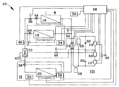
A heat pump system 10 in accordance with a preferred embodiment
of the present invention is schematically represented in Figure 1. The heat
pump system 10 will be described with particular reference to residential
house applications in nordic climates, it will be understood that the system
10
of this invention can find use in other applications and operating
environments.
As shown in Figure 1, the heat pump system 10 includes a low-stage
compressor 12, a high stage compressor 14, an indoor refrigerant-water heat
exchanger 16, an indoor refrigerant-air heat exchanger 18 for delivering
heating and cooling air to the interior of the house (not shown), an outdoor
refrigerant-air heat exchanger 20, a closed economizer 22, a four-way
reversing valve 24, a lubricant separator 26, a suction gas accumulator 28,
check valves 30 and 32 in fluidic parallel with the compressors 12 and 14,
respectively, a control valve 34 for adjusting the refrigerant flow rate
through
the heat exchanger 18, a solenoid valve 36 to block refrigerant flow to the
heat exchanger 16, expansion devices 38, 40, 42, and 44 to control
refrigerant flow through the heat exchanger 20, heat exchanger 18,
economizer 22, and heat exchanger 16, respectively, a solenoid valves 46
and 48 for controlling refrigerant flow and lubricant flow, respectively, in
the
compressors 12 and 14, a mixing chamber 50 for mixing two-phase
refrigerant from the economizer 22 and refrigerant vapor from the compressor
-9-
CA 02597372 2007-08-15
CWCAS-1 83
12, outdoor, indoor, and floor temperature sensors 52, 54, and 56, pressure
sensors 58 and 60 for sensing the evaporating and condensing pressures
within the heat pump system 10, and a control unit 62 for controlling the heat
pump system 10 and its various components. As described above, the heat
pump system 10 is configured for use with an interior hydronic system (not
shown) coupled with the indoor refrigerant-water heat exchanger in
combination with a forced air heating/cooling system coupled with the indoor
refrigerant-air heat exchanger 18. However, preferred aspects of the heat
pump system 10 may also be used with any conventional interior heat
exchange system, such as a conventional forced air heating/air-conditioning
system.
The system 10 can be generally and preferably physically separated
into three main units, as indicated in Figure 1. An indoor heating/cooling
unit
of the system 10 includes the heat exchanger 18 (with fan), expansion device
40, and temperature sensor 54, all of which can be located inside a
heating/cooling duct system of the house. An outdoor unit of the system 10
includes the heat exchanger 20 (with fan), expansion device 38, and
temperature sensor 52, all of which can be located outside the house for
absorbing heat from and dissipating heat to the ambient outside environment
outside the house. Finally, the main unit of the system 10 contains the
remaining system components, including the compressors 12 and 14,
economizer 22, heat exchanger 16, control unit 62, etc.
The operation of the system 10 will now be described in reference to
the following modes of operation: a two-stage heating mode for very cold
ambient temperatures; a single-stage heating mode for cooler ambient
temperatures; an air-conditioning (cooling) mode for warm to hot ambient
temperatures; and a defrosting mode for defrosting the coils of the outdoor
heat exchanger 20 during winter.
-10-
CA 02597372 2007-08-15
CWCAS-183
Figure 2 schematically depicts the heat pump system 10 of Figure 1
(the electrical components are omitted for clarity) in its two-stage heating
mode for very cold ambient temperatures. As shown in Figure 2, both
compressors 12 and 14 are operated in series to meet the heating demands
of a very cold ambient temperature. In this scenario, both the low stage
compressor 12 and the high stage compressor 14 are activated and valves 30
and 32 are closed. The compressor 12 compresses the refrigerant from a low
pressure to an intermediate pressure. The hot refrigerant vapor discharged
from the compressor 12 then flows to the mixing chamber 50 where it is
mixed with the two-phase refrigerant from the economizer 22 in order to reach
a suitable lower inlet temperature for the high stage compressor 14. The
temperature at the inlet of the compressor 14 is regulated with the expansion
valve 42, which controls the refrigerant temperature at the inlet to the
compressor 14 by adjusting the refrigerant flow rate through the economizer
22.
After compressing the refrigerant from the intermediate pressure
achieved with the compressor 12 to the higher pressure achieved with the
compressor 14, the gaseous refrigerant passes through a lubricant separator
26 where the lubricant (oil) is separated from the refrigerant. The lubricant
is
fed to the conduit connected to the inlet of the compressor 12, and is
therefore drawn into the compressor 12 so that the lubrication of both
compressors 12 and 14 is provided under all operating conditions.
After leaving the lubricant separator 26, the refrigerant vapor passes
through the reversing valve 24 and enters the heat exchanger 16 (operating
as a water-cooled condenser). At this point, two different interior heating
scenarios are provided. In a first scenario, if the air heating to the house
is
switched off, the control valve 34 is closed and all of the refrigerant passes
through the heat exchanger 16 where it is liquefied and transfers heat to the
return water of the hydronic system, after which the resulting liquid
refrigerant
- 11 -
CA 02597372 2007-08-15
CWCAS-1 83
passes through the bypass valves of 44 and 36. In the second scenario, if air
heating to the house is switched on, the control valve 34 is open and part of
the refrigerant will pass through the air-cooled condenser 18 and release heat
to the air of the forced air heating/cooling system of the house. The capacity
of the heat exchanger 18 is preferably smaller than the capacity of the heat
exchanger 16, so that at least a portion of the refrigerant passes through the
heat exchanger 16. The control valve 34 is controlled by the surface
temperature of the heat exchanger 18 and the outlet temperature of the heat
exchanger 18 to ascertain a certain subcooling of the refrigerant.
The liquid refrigerant exiting the heat exchanger 18 joins the
refrigerant stream from the solenoid valve 36 and then flows through the
economizer 22, where heat is extracted, as understood by those skilled in the
art and discussed below. After passing through the economizer 22, the
refrigerant is separated into two portions. A smaller portion of the
refrigerant
passes through the expansion valve 42 to the economizer 22, where it is
partly evaporated. The partially evaporated (two-phase) refrigerant then
passes though the solenoid valve 46 and into the mixing chamber 50, where it
is mixed with the hot discharge vapor from the compressor 12 as described
above. The remaining and larger portion of the refrigerant passes through the
expansion device 38, which is controlled by the superheat of the heat
exchanger 20. The refrigerant then passes through the heat exchanger 20,
where it evaporates using heat drawn from the ambient air outside the house.
Afterwards, the refrigerant flows through the reversing valve 24 to the
suction
gas accumulator 28, which regulates the refrigerant flow to the compressors
12 and 14 and thus protects the compressor 12 from damage, especially
during the startup of the system 10. The refrigerant vapor leaving the suction
gas accumulator 28 is then mixed with the lubricant leaving the lubricant
separator 26 and enters the compressor 12, at which point the cycle repeats.
Figure 3 represents the single-stage heating mode of the heat pump
-12-
CA 02597372 2007-08-15
CWCAS-1 83
system 10 suitable for operation in cool ambient temperatures. In this mode,
only one of the compressors 12 and 14 need be operated (with the other
bypassed) to meet the lower heating requirements of the cool ambient
temperatures. The check valve 30 in fluidic parallel with the compressor 12 is
open so that the low stage compressor 12 is bypassed, and the check valve
32 is closed so that the refrigerant is directed exclusively to the high stage
compressor 14, which therefore is operated independently to compress the
refrigerant from low pressure to high pressure. Alternatively, the check valve
30 could be closed and the check valve 32 opened so that the refrigerant flow
is directed exclusively to the low stage compressor 12, with the high stage
compressor 14 being bypassed. If the compressor 12 is operated
independently, the refrigerant is first compressed by the compressor 12
before entering the mixing chamber 50, which is inactive as a result of the
solenoid valve 46 being closed, as discussed below. From the mixing
chamber 50, the refrigerant bypasses the compressor 14 by using the flow
path through the check valve 32 and enters the lubricant separator 26.
Thereafter, the refrigerant circuit functions essentially the same as the two-
stage mode described above with reference to Figure 2. When the refrigerant
vapor passes through the lubricant separator 26, the lubricant is separated
from the refrigerant and added back to the low pressure line to the
compressors 12 and 14 in order to guarantee lubrication for the compressors
12 and 14. After leaving the lubricant separator 26, the refrigerant passes
through the reversing valve 24 and enters both the heat exchanger (water-
cooled condenser) 16 and the control valve 34, at which point the two
different scenarios for water-heating only and combined air-heating and
water-heating can be carried out, as described above.
After the liquid refrigerant leaves the indoor heat exchangers 16
and/or 18, it enters the inactive economizer without changing its state since
flow through the injection line to the economizer 22 is prevented by the
closed
-13-
CA 02597372 2007-08-15
CWCAS-1 83
solenoid valve 46. Because of the solenoid valve 46 is closed, the refrigerant
stream is not split into the two above-noted portions after leaving the
economizer 22. Instead, the entire refrigerant volume is expanded by the
expansion device 38, which is again controlled by the superheat of the
outdoor heat exchanger 20. The refrigerant then passes through the heat
exchanger 20, where it evaporates using heat drawn from the ambient air
outside the house. Thereafter, the refrigerant flows through the reversing
valve 24 to the suction gas accumulator 28, which regulates the refrigerant
flow to the compressors 12 and 14 as discussed above. The refrigerant
vapor leaving the suction gas accumulator 28 is then mixed with the lubricant
leaving the lubricant separator 26, at which point the cycle repeats.
Figure 4 represents the air-conditioning (cooling) mode suitable for
warm to hot ambient temperatures. As shown in Figure 4, to operate in the
air-conditioning mode, the solenoid valves 36 and 46 are closed, the control
valve 34 is opened, and the reversing valve 24 is actuated to an air-
conditioning position. The low pressure refrigerant vapor bypasses the
compressor 12 by using the flow path through the check valve 30, and is
compressed in the compressor 14. The refrigerant vapor then flows to the
lubricant separator 26, where the lubricant is separated from the refrigerant
and added back to the low pressure line to the compressors 12 and 14 as
discussed previously. After leaving the lubricant separator 26, the
refrigerant
vapor passes through the reversing valve 24 to enter the outdoor heat
exchanger 20 (now acting as a condenser), where the refrigerant condenses
by dissipating heat to the ambient air drawn by the fan through the heat
exchanger 20. The liquid refrigerant then flows through the economizer 22,
which again is inactive as a result of the valve 46 being closed. As a result,
the state of the refrigerant remains unchanged. In addition, the solenoid
valve 36 is closed, causing the refrigerant to enter the indoor heat exchanger
18 after passing through the expansion device 40, which is controlled by the
-14-
CA 02597372 2007-08-15
CWCAS-1 83
evaporating pressure and outlet temperature of the heat exchanger 18. While
passing through the heat exchanger 18, the refrigerant evaporates by
absorbing heat from the air stream drawn from the house interior, thus cooling
the indoor air. Finally, the refrigerant flows through the open control valve
34
and through the reversing valve 24 to the suction gas accumulator 28, is
mixed with the lubricant leaving the lubricant separator 26, and proceeds to
the valve 30, at which point the cycle repeats.
Figure 5 represents the defrosting mode of the system 10 for
defrosting the outdoor coil of the heat exchanger 20, as need from time to
time during winter as a result of ice buildup exceeding a predetermined limit.
The ice buildup, caused by freezing of the moisture of the ambient air at
evaporating temperatures below the freezing point, decreases the efficiency
of the system 10 because the airflow across the coil of the heat exchanger 20
is reduced and the evaporating temperature of the heat pump decreases.
In order to enter the defrost mode, the compressor 12 is turned off
and the solenoid valve 46 is closed while compressor 14 is running. The
reversing valve 24 is then changed to air-conditioning mode, the solenoid
valve 36 is kept open, and the control valve 34 is closed. This condition is
held as long as the defrosting cycle lasts, which can be terminated either by
a
timer or a temperature control on the coil of the heat exchanger 20. The
outdoor fan can also be turned off in order to decrease the heat loss over the
coil and, therefore, reduce the defrost time. To leave the defrosting mode,
the reversing valve 24 is switched back to heating mode and the other valves
are switched back to their positions before entering the defrost mode.
In Figure 5, only the high stage compressor 14 is indicated as running
in the defrost mode. The low pressure refrigerant from the suction side
bypasses the compressor 12 by using the flow path through the check valve
30, and is then compressed by the compressor 14 before flowing to the
-15-
CA 02597372 2007-08-15
CWCAS-1 83
lubricant separator 26, whose operation is the same as that described above
for the other operating modes. After leaving the lubricant separator 26, the
refrigerant passes through the active reversing valve 24 and enters the heat
exchanger 20, where it condenses by dissipating heat to the heat exchanger
20. if the outdoor air fan is turned off, most of the refrigerant heat is used
to
melt the frost and, therefore, defrost the outdoor coil. After leaving the
heat
exchanger 20, the liquid refrigerant flows through the device 38 and flows
through the economizer 22, which is again inactive because the valve 46 is
closed. The refrigerant, whose state is unchanged by the inactive economizer
22, flows to only the heat exchanger 16 as a result of the valve 34 being
closed and the valve 36 being open. Before entering the heat exchanger 16,
the refrigerant is expanded by the expansion device 44, after which the
expanded refrigerant is evaporated in the heat exchanger 16 using the heat of
the hydronic system, which has an almost imperceptible effect on the
hydronic system since the thermal mass of the hydronic system is high and
the duration of the defrost mode is short. After leaving the heat exchanger
16, the liquid refrigerant proceeds to the reversing valve 24 and then the
suction gas accumulator 28, where the remaining cycle is the same as
described for the other modes of operation.
As known in the art, because of the inherently different lubricant
circulation rates of the two compressors 12 and 14, the system 10 will
experience lubricant migration from one compressor to the other depending
on the operating conditions of the system 10. If the level of the lubricant
sump of one compressor is too low, lubrication cannot be guaranteed for that
compressor and the reliability of the compressor will decrease drastically.
Therefore, lubricant equalization is essential to keep the system 10 running.
To address this issue, the heat pump system 10 of this invention preferably
incorporates a lubricant equalization subsystem that operates when both
compressors 12 and 14 are not operating, since the difference in suction
-16-
CA 02597372 2007-08-15
CWCAS-183
pressure of the compressors 12 and 14 is much higher than the static
pressure difference of the different heights in lubricant level. Lubricant
equalization is accomplished by opening the solenoid valve 48 (shown closed
in Figures 2 through 5) whenever both compressors 12 and 14 are not
operating. To ensure the lubricant will equalize when the valve 48 is opened,
both compressors 12 and 14 are preferably mounted at the same level so that
the static pressure difference between the lubricant level of the compressors
12 and 14 is negligible. Lubricant equalization can be initiated by the
control
unit 62 whenever the heat pump system 10 is turned off, and is automatically
terminated by the control unit 62 before starting either of the compressors 12
or 14.
During colder months, the system 10 can be operated in either of the
two-stage or single-stage heating modes. According to a preferred aspect of
the invention, the single-stage heating mode is preferably used whenever the
pressure ratio between the evaporating and condensing pressures is small. If
the pressure ratio between the evaporating and condensing pressures rises to
a predetermined level at which the compressors 12 and 14 could be damaged
when operating in the single-stage mode, the control unit 62 causes the other
compressor 12 or 14 to start, and the heat pump system 10 begins operating
in the two-stage mode. As represented in Figures 1 through 5, the
evaporating and condensing pressures can be measured directly using the
pressure sensors 58 and 60, respectively, which are shown at preferred
locations within the system 10, though other locations are possible as long as
one of the sensors 58 or 60 is on the high pressure side and the other on the
low pressure side of the system 10. Alternatively, these pressures could be
calculated from the evaporating and condensing temperatures as measured
by temperature sensors. However, this approach would require placement of
temperature sensors directly at the heat exchangers 16, 18, and 20. After
obtaining the evaporating and condensing pressures using either method, the
-17-
CA 02597372 2007-08-15
CWCAS-1 83
ratio of the evaporating pressure to the condensing pressure can be
calculated by the control unit 62.
The two-stage operation of the heat pump system 10 can also be
initiated if the required heat load is higher than a predetermined limit
exceeding the heat output of a single compressor. To decide which
compressor 12 or 14 is running in single-stage mode, two conditions can be
applied. First, damage to the compressors 12 and 14 must be prevented by
not exceeding the operation limits of either compressor 12 and 14. Second,
the particular compressor 12 or 14 to be operated in the single-stage mode
may be selected based on the heat demand. The states of the different
valves have already been defined in the description of the four different
operating modes depicted in Figures 2 through 5. The temperatures to detect
the heat demand and the limiting conditions of the compressors 12 and 14
are preferably measured at the outdoor coil of the heat exchanger 20, on the
indoor coil of the heat exchanger 18, in the ambient air, and at the floor or
indoor air of the house. Additional sensors may also be used to improve the
control and allow for greater flexibility.
A schematic of the heat output of the described heat pump system 10
and the heat demand for a residential house versus the ambient temperature
is plotted in Figure 6. As described above, the compressors 12 and 14 are
capable of being operated independently or in series for maximum output,
depending on the demands of the environmental conditions. The
compressors 12 and 14, which can be lowcost fixed-speed compressors of
known design, can also be operated with or without the economizer 22,
depending on the required heating capacity. Thus, as shown in Table I
below, six separate operating capacities may be achieved with the heat pump
system 10 using fixed-speed compressors.
-18-
CA 02597372 2007-08-15
CWCAS-183
TABLE I
OPERATING MODE COMPRESSORS ECONOMIZER
12 14 22
2-Stage Heating with Economizer 22 ON ON ON
2-Stage Heating without Economizer 22 ON ON OFF
1-Stage heating with Compressor 12 ON OFF OFF
1-Stage heating with Compressor 14 OFF ON OFF
1-Stage cooling with Compressor 12 ON OFF OFF
1-Stage cooling with Compressor 14 OFF ON OFF
Alternatively, a variable speed compressor may be used as the high-
stage compressor 14 to achieve still further flexibility in heating capacity.
As
shown in the following chart, ten separate operating capacities may be
achieved with this approach.
TABLE II
OPERATING MODE COMPRESSORS ECONOMIZER
12 14 22
2-Stage Heating with Economizer 22 ON HIGH ON
2-Stage Heating without Economizer 22 ON HIGH OFF
2-Stage Heating with Economizer 22 ON LOW ON
2-Stage Heating without Economizer 22 ON LOW OFF
1-Stage heating with Compressor 12 ON OFF OFF
1-Stage heating with Compressor 14 OFF HIGH OFF
1-Stage heating with Compressor 14 OFF LOW OFF
1-Stage cooling with Compressor 12 ON OFF OFF
1-Stage cooling with Compressor 14 OFF HIGH OFF
1-Stage cooling with Compressor 14 OFF LOW OFF
-19-
CA 02597372 2007-08-15
CWCAS-1 83
In view of the above, the present heat pump system 10 offers various
advantages over existing heat pump systems. The flexible configuration of
the compressors 12 and 14 and economizer 22 allows for the generated heat
to closely follow and quickly respond to ambient conditions and heat
demands, improving the thermal comfort of the interior of a house and
decreasing the costs of operation. System performance is increased because
the system 10 does not need to cycle on and off as frequently as prior art
systems. The multiple compressor configuration of the present invention can
also be easily adapted to existing air handling and heat exchange systems,
allowing the present invention to be easily adapted to existing systems.
The lubricant management system is configured to accommodate the
needs of multiple compressors configured to operate in series, and provides
better performance by preventing lubricant flow through the heat exchangers
16, 18 and 20. Specifically, performance is increased because the thermal
resistance of the heat exchangers 16, 18, and 20 is lower if a lubricant film
is
not present on their tube walls. Also, the lubricant equalization between the
compressors 12 and 14 ensures more even lubrication of the compressors 12
and 14 to improve system performance and reliability of the compressor
section of the heat pump system 10. The flow path on the suction side of the
compressors 12 and 14 also inhibits lubricant from migrating to the inactive
compressor 12/14 while the system 10 is running in the single-stage mode,
further improving the reliability of the system 10.
Another advantage is that the system 10 can be configured to be
physically separated into three units: an indoor air unit containing the heat
exchanger 18 (and accessories); an outdoor air unit containing the heat
exchanger 20 (and accessories); and a main unit containing the compressors
12 and 14, heat exchanger 16, control unit 62, economizer 22 (optional), and
accessories. Because of the lower weight and smaller size of each
component of the system 10, transport of the components is easier and less
-20-
CA 02597372 2007-08-15
CWCAS-1 83
expensive. The separation of the compressors 12 and 14 from the heat
exchangers 18 and 20 is advantageous because the outdoor unit (containing
the heat exchanger 20) does not include the compressors 12 and 14, allowing
for a greater degree of freedom for the design of the heat exchanger 20, with
the potential for increased performance, more economical construction, and
optimization of the drainage of condensate from the heat exchanger 20.
Furthermore the compressors 12 and 14 can be installed to be more easily
serviced since they are not required to be surrounded by any of the heat
exchangers 16, 18, and 20. The compressors 12 and 14 can also be housed
in a noise-damping enclosure since openings for air coiis are not needed.
Because the compressors 12 and 14 are the loudest part of the system 10,
the noise level of the overall system 10 can thus be reduced. The
compressors 12 and 14 may also be located indoors, eliminating the need for
crankcase heating on startup and providing better performance, lower running
cost, and increased reliability.
While a particular embodiment has been described and represented
in the Figures, various modifications are also within the scope of the
invention. For example, though the heat pump system 10 has been
described for use as a residential heating and cooling system, the present
invention is not limited to residential applications, but could also be used
in
commercial and industrial applications and accommodations. In addition, the
expansion valve 42 and solenoid valve 46 could be replaced by a single
electronic expansion valve to provide more accurate control of the refrigerant
flow and to eliminate the need to use two valves. A bypass solenoid valve
could be installed parallel to the compressor 12 and its bypass valve 30 to
more quickly equalize the suction pressures of the compressors 12 and 14.
Such a modification can more rapid lubricant equalization immediately after
the compressors 12 and 14 are turned off and the bypass solenoid valve is
opened. Another possible modification is to rely on natural defrosting at
-21 -
CA 02597372 2007-08-15
CWCAS-183
ambient temperatures above, for example, 2 C, since air at such
temperatures can provide enough heat to defrost the coil of the heat
exchanger 20 by providing air flow through the outdoor coil.
In view of the above, though the invention has been described in
terms of a preferred embodiment, it is apparent that other forms could be
adopted by one skilled in the art. Therefore, the scope of the invention is to
be limited only by the following claims.
-22-