Note: Descriptions are shown in the official language in which they were submitted.
CA 02597710 2007-08-13
WO 2006/088816 PCT/US2006/005078
APPARATUS FOR CLEANING PIPES HAVING PUMPING AND VACUUMING
CAPABILITY
[0001] The present invention claims priority to United States Application
11/057,260, which was filed on February 14, 2005, which is incorporated by
reference herein
in its entirety.
TECHNICAL FIELD
[0002] The present invention relates generally to cleaning waste collection
systems such as but not limited to sewers, sumps, wet wells, collection tanks,
digesters,
clarifiers, classifiers, etc. and in particular to cleaning and removal of
solid and liquid
materials therefrom.
BACKGROUND OF THE INVENTION
[0003] Waste collection systems such as sewers, sumps, wet wells, digesters,
clarifiers, classifiers, collection tanks, etc. must be cleaned periodically
in order to maintain
proper fluid flow and capacity. Cleaning removes sand and other deleterious
materials that
have infiltrated' into, for example, a sewer as well as solid materials that
have settled out from
the normally slow moving waste slurry that varies in volume and flow rate
depending on the
collective amount of effluents emptied into the waste collection system over
time. In order to
properly clean large capacity waste collection systems such as collection
tanks or the vast
lengths of sewer lines in a typical city, an efficient and cost effective
method of cleaning
must be employed that can handle the large volume of material that must be
removed from a
typical waste collection system.
[0004] Typically, commercial waste cleaning operations utilize a water jet
router made up of a high pressure water pump feeding pressurized wash water
through a hose
having a cleaning head on its end. This cleaning head has water nozzles on its
back face
which creates a jet action resulting from the high pressure water flowing out
the nozzles. The
high pressure water jet action both washes the downstream waste collection
system such as
sewer pipe and propels the cleaning head upstream for continuous washing
action of the
entire length of the waste collection system such as sewer pipe being cleaned.
The position
1
CA 02597710 2007-08-13
WO 2006/088816 PCT/US2006/005078
of the cleaning head and its rate of forward travel is regulated by control of
the hose reel
integrally mounted on the washing truck.
[0005] Commercial waste cleaning operations then utilize one or the other of
the following two known systems and methods for moving the resulting water
slurry
produced from the washing action into a collection box, where the solid
material is removed
and disposed of in a dump or landfill.
[0006] First, a second hose may be lowered into a manhole downstream of the
cleaning head and is in communication with the resulting water slurry produced
from the
washing action. This hose is connected to a vacuum system which lifts the
water slurry and
all contained debris up from the bottom of the manhole into a vacuum holding
tank mounted
on the rear of the wash truck. Thus, the high pressure wash water brings the
solid materials
suspended in water to the manhole and the vacuum action picks up the waste
material and
deposits it into the truck-mounted holding container. When the container
becomes full, the
materials contained in the container are removed and disposed of, typically in
a dump or
landfill.
[0007] Second, the operation may include a semi-submersible pump to move
the water slurry produced by the washing action into the collection box. The
submersible
pump pushes the slurry up in a column through a slurry hose which is connected
to and
deposit the slurry into a pressurized collection container located on the
surface. Again, when
the container becomes full, the materials contained in the container are
removed and disposed
of, typically in a dump or landfill.
[0008] Choosing between the use of a submersible pump to push the waste
water slurry into the collection container or use of a vacuum to suck the
slurry into the
container turns largely on the conditions within the waste water system. If,
for example,
there is a large volume of liquid relative to solids in the slurry, vacuuming
becomes very
inefficient and possibly infeasible. A vacuum typically pulls out liquid much
more easily
than the solid material in the slurry. Thus, when a large volume of liquid is
in the slurry, the
vacuum may pull out only the liquid, leaving the solid material in the waste
water system. A
submersible pump, by contrast, requires a large volume of liquid to
effectively push the slurry
2
CA 02597710 2007-08-13
WO 2006/088816 PCT/US2006/005078
upward into the collection box. If very little liquid is present in the waste
water system, a
pump will be inefficient or may not work at all, and a vacuum is required.
[0009] Existing technologies typically include a truck or other apparatus with
a
high pressure washer, and either a pump or vacuum for moving the waste water
slurry into
the collection box. Because field conditions dictate which type of technology
is used,
though, it is generally necessary to go to the particular waste water system
to be cleaned and
examine the conditions before choosing an apparatus to perform the work and
delivering the
apparatus to the jobsite.
BRIEF SUMMARY OF THE INVENTION
[0010] In contrast to the prior waste cleaning apparatus and methods, the
apparatus of the present invention is designed to eliminate the need to
examine field
conditions prior to dispatching a cleaning apparatus to the jobsite. The
apparatus of the
present invention has improved the overall cost and efficiency of cleaning
waste water
systems by using a new, novel and non-obvious combination of apparatus and
techniques
known in the art.
[0011] The apparatus of the present invention is directed to continuous
cleaning
of waste collection systems such as city sewers, sumps, wet wells, digesters,
clarifiers and
collection tanks by high pressure water washing of the waste collection system
and collection
of the resulting solid materials washed therefrom. The present invention may
clean any
system or device that collects solids, liquids or both. The invention may
comprise (1) a
source of high pressure water; (2) a submersible pump capable of pumping
solids and liquids;
(3) a vacuum system capable of vacuuming solids and liquids; (4) a pressurized
container
where solid materials separate from the liquids (water) by gravity; (5) means
to remove the
water in the pressurized container separated from the solid materials
(decanted water); and
(6) means to reuse the decanted water for cleaning of the waste collection
system.
[0012] The high pressure water source may be a truck-mounted pump
connected to a water tank or fire hydrant for its source of water. This
pumping truck
additionally may comprise a high pressure water hose attached to the pump and
a
hydraulically actuated hose reel. Mounted at the other end of the high
pressure hose may be a
bullet-shaped cleaning head. The cleaning head has water jet orifices on its
rear face. When
3
CA 02597710 2007-08-13
WO 2006/088816 PCT/US2006/005078
high pressure washing water exits through these orifices, the cleaning head is
propelled
forward by jet action. Rate and distance of cleaning head movement is operator
controlled by
the hose reel and the tethering restraint of the hose attached to the head.
For example, the
cleaning head and its attached hose is lowered into a manhole and then placed
into the sewer
pipe to be cleaned. Next, high pressure water is forced through the rear jets
of the cleaning
head propelling it into the sewer pipe.
[0013] A source of high pressure water may also be derived from a kite. A kite
is a funnel made up of flexible material such as, for example, canvass which
is restrained by
lines to a cable that goes back to the upstream manhole of the waste
collection system, such
as a sewer. When the kite is placed into a pipe of the waste collection
system, water backs up
behind it and reduces the flow of water through the pipe to the flow of water
that can pass
through the diameter of an opening in the end of the kite funnel.
[0014] As head pressure builds up behind the kite, water squirts out of the
furmel opening like from a high pressure fire hose. For example, at 30 feet of
head pressure
and a 30-inch diameter pipe reduced to a six-inch opening, there may be 400
psi water
coming out of that six-inch hole at the end of the kite fumlel. This water
pressure is much
more than can be generated by a hose/nozzle head as described above. The kite
may be
reeled downstream through the pipe by paying out the cable attached thereto.
As the kite
moves downstream through the waste collection system, the solid debris is
washed toward the
submergible pump or vacuum system.
[0015] Yet another source of high pressure water is the Wayne ball. A Wayne
ball is a ball that is approximately the same size as the inside diameter of
the pipe being
cleaned. This ball has concentric helical grooves cut into its surface in
which water runs
through the grooves and spins the ball. As the Wayne ball spins it agitates
the surrounding
material in the pipe and moves this material ahead of the Wayne ball toward
the submergible
pump or vacuum system. The Wayne ball is restrained, like the kite above, on a
cable
attached pivotally to the ball and allowing the ball to spin from the water
flowing through the
helical grooves. Water pressures obtained with a Wayne ball are similar to
those pressures
obtained with a kite.
[0016] Pumping waste slurrX
4
CA 02597710 2007-08-13
WO 2006/088816 PCT/US2006/005078
[0017] The washing action of the high pressure water flowing through the
above water pressure sources produces a slurry of waste material solids
suspended in the
wash water and any other liquids present in the waste collection system. If a
substantial
amount of liquid exists in the waste water system, a submersible pump is used
to push the
-waste slurry created by the high pressure washing action into a pressurized
collection box on
the surface. The submersible pump has a greater pumping capacity in gallons
per minute
("GPM") than does the water flow even with the additional wash water. Thus,
little or no
flow gets past this submersible pun7p. The submersible pump is capable of
lifting almost
pure solids to the surface above the waste collection system. On the surface,
a pressurized
waste container is used for the collection of the slurry.
[0018] The pressurized container receiving the slurry from the submersible
pump works with a positive pressure to atmosphere. This allows rapid
settlement to the
bottom of the container of the solid materials in the slurry by means of
gravity. Thus, the
water contained in the slurry will float to the top of the settled solids and
may be easily
removed and reused and only the solids need to be transported away and
disposed of at a
dump.
[0019] In practice, the slurry hose is in communication with the top of the
pressurized container and the solid material rapidly falls out of the incoming
slurry in a
cascade gradient where the highest part of the solid material pile is closest
to the slurry inlet.
Means for removal of water separated from the slurry ("decanted water") allows
the
apparatus of this invention to continuously reuse a substantial amount of the
wash water for
further cleaning operations. Thus, a significant advantage of the submersible
pump is the
conservation of water by almost total capture and subsequent reuse of both
wash water and
normal sewer water flow.
[0020] Filtered decanted water may be used as a water source for the high
pressure water pump. In addition, excess decanted water may be emptied
upstream of the
washing operations, thus, improving existing cleaning operations water flow.
In practice,
faster and better waste collection system washing operations are achieved when
the water
flow and volume are increased. Thus, as mentioned above, the submersible pump
does not
require a limited water flow as does the vacuum system, and actually benefits
from increased
water flow.
CA 02597710 2007-08-13
WO 2006/088816 PCT/US2006/005078
[0021] A submersible pump is also capable of handling a much higher flow
capacity than a vacuum system. For example, a vacuum system can handle only
about 700
GPM of waste slurry. A pump, by contrast, can typically handle about 2,500 GPM
of slurry.
Thus, a submersible pump may be preferred in some situations because it can
pump slurry
into the collection container at a much higher rate than the vacuum can
handle.
[0022] Using a submersible pump with a positive pressure collection container
allows for decanting slurry water back into the manhole as the solid material
settles out in the
collection box simultaneously with the pumping of waste slurry into the
collection box. This
simultaneous decanting is unavailable using a vacuum system. Thus, when using
a
submersible pump, the process needs to be stopped to unload the material from
the collection
box only when the box is completely filled with solid material. By contrast,
vacuuming must
cease when the collection box fills up with a combination of solid material
and liquid. The
more frequent stoppage using a vacuum system results in less efficient
operation.
Subsequently, use of a submersible pump allows for cleaning more length of
pipe per time
interval than does vacuuming.
[0023] Vacuuming waste slurrX
[0024] A submersible pump requires a significant amount of liquid in the
system to be cleaned in order to operate effectively. When there is not enough
liquid to
utilize the pumping system, the present invention is capable of using a vacuum
system to
handle drier materials in much the same way as conventional vacuum cleaning
systems. As
discussed above, the vacuum system is somewhat less efficient than the pumping
system.
However, in dry conditions it is necessary to use a vacuum rather than a pump
to move waste
slurry to the surface and into the collection container. Unlike any previously
utilized
technology, the present invention may be easily converted between pumping and
vacuuming
as conditions dictate.
[0025] An object of the present invention is to efficiently wash sewer and
other
pipe lines by using either a submersible pump or vacuum technology to move
waste slurry
scrubbed from the pipe by high pressure water to the surface and into a
collection container.
6
CA 02597710 2007-08-13
WO 2006/088816 PCT/US2006/005078
[0026] A further object of the present invention is to switch quickly and
easily
between a submersible pump and vacuum technology to move waste slurry scrubbed
from a
pipe by high pressure water to the surface and into a collection container.
[0027] Yet a further object of the present invention is to provide an
apparatus
capable of utilizing either a submersible pump or vacuum technology to move
waste slurry
scrubbed from a pipe by high pressure water to the surface and into a
collection container,
such that pipe conditions and liquid content do not need to be identified
prior to dispatching
the apparatus to the jobsite.
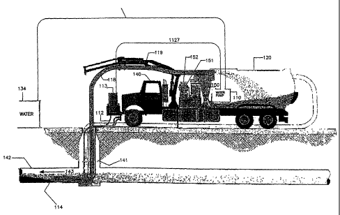
BRIEF DESCRIPTION OF THE DRAWINGS
[0028] FIG. 1 is a view of an embodiment of the apparatus of the present
invention wherein a submersible pump is utilized to pump the waste slurry into
the waste
container;
[0029] FIG. 2 is a view of an embodiment of the apparatus of the present
invention wherein a vacuuming system is utilized to move the waste slurry into
the waste
container;
[0030] FIG. 3 is a rear view of a cleaning head;
[0031] FIG. 4 is a view of a kite as used in the present invention;
[0032] FIG. 5 is a front view of the kite of FIG. 4; and
[0033] FIG. 6 is an elevational view of a Wayne ball as used in the present
invention.
DETAILED DESCRIPTION OF EXEMPLARY EMBODIMENTS
[0034] Referring now to FIGS. 1 and 2, the system of the present invention
comprises a high pressure water pump assembly 10 for generating high pressure
water, a high
pressure water hose 12, a hose reel 13, a bullet-shaped cleaning head 14 for
receiving high
pressure water and cleaning a sewer, a submersible pump 16 for pumping a
slurry of solids
and liquids out of the sewer when the slurry contains a large amount of
liquid, a power source
17 for the submersible pump 16, a slurry hose 18, a waste container 20 for
receiving the
7
CA 02597710 2007-08-13
WO 2006/088816 PCT/US2006/005078
pumped slurry, a decant water hose 22, a decant water outlet 24 for releasing
the water from
the container, main supply water line 32, and main supply water source 34. The
invention
may be mounted to a truck 40 as seen in FIGS. 1 and 2, or to an immobile unit
that must be
towed to and from a jobsite. For consistency, the unit will be described as a
truck throughout
this document.
[0035] The high pressure water pump assembly 10 and pump power source 17
are mounted on, for example, a truck 40 and may use the truck engine for
power. The
purpose of the pump assembly 10 is to pressurize water for use in washing
sewer lines 42 by
means of cleaning head 14 attached to and in communication with high pressure
water hose
12. The source of water for pump assembly 10 may be derived from any water
source 34,
including a fire hydrant, a tank on the truck 40, or from the sewer 42 itself.
[0036] The cleaning head 14 is bullet-shaped with a front and rear face. The
rear face of the cleaning head 14 has water jet outlets 15 directed
backwardly. The truck 40,
high pressure water hose 12 and cleaning head 14 may be of any suitable
conventional
equipment. When the cleaning head 14 is lowered through a manhole 41, and into
a sewer
42, high pressure water, such as 2000 psi is applied through the hose 12 to
the cleaning head
14. The high pressure water applied to the cleaning head 14 has several
functions. First, the
water sprays out of the outlets 15 and the exiting high pressure water washes
the solid
material from the walls of the sewer 42 and suspends the sewer pipe solid
material in a slurry.
Additionally, the high pressure water being applied to the cleaning head 14
moves the
cleaning head 14 in a direction 43. After cleaning the sewer 42, the cleaning
head 14 may be
retrieved by retracting the high pressure water hose 12 by means of hose reel
13 as is
conventional.
[0037] If conditions dictate that a submersible pump 16 should be used, i.e.,
if a
relatively high volume of liquid exists in the sewer 42, a submersible pump 16
is provided
with a capacity of more than the total flow of water being injected to the
cleaning head 14 as
well as any normal sewer flow. It is desirable to have a large water content
in the sewer 42
for efficiently cleaning the sewer 42 by suspending the solid particles and
material in the
sewer 42 in a liquid slurry. The submersible pump 16 is capable of pumping a
slurry having
up to 80% solids.
8
CA 02597710 2007-08-13
WO 2006/088816 PCT/US2006/005078
[0038] For example only, if the high pressure water pump provides a flow of 60
gallons per minute, a suitable submersible pump 16 capable of removing 2000
gallons a
minute of 80% solid material is desirable for allowing the present invention
to clean an
operating sewer having flowing fluids therein. While any suitable submersible
pump 16 may
be provided, pump series 53, sold by Gamer Environmental Services, Inc., is
satisfactory.
Such pumps can be powered hydraulically and powered by diesel, electric
motors, gasoline
engines or any other available power source.
[0039] The fluidized slurry from the submersible pump 16 is transmitted
through the slurry hose 18 to a waste container 20. The fluidized slurry
enters the top of the
container 20, where the solids and water separate and the solids settle to the
bottom of the
container by gravity. If desired, baffles may be provided in the container 20
to assist in the
separation. The water is then decanted from the container 20 and as the
container 20 fills up,
the decanted water is released from the container 20 by means of the positive
pressure forcing
the water through a decant water hose 22.
[0040] The waste container 20 may be either permanently affixed to the truck
40, or may be removable therefrom. If the waste container 20 is removable,
when the
container 20 is substantially filled up with solid particles, it may be
removed and a
replacement container 20 may be rolled into place and connected to hoses 18
and 22. The
filled container 20 may then be removed to a dump site while the truck 40
remains on site and
continues the cleaning operation. If the waste container 20 is permanently
affixed to the
truck 40, the truck 40 must go to the dump site each time the waste container
20 becomes
substantially filled up with solid materials.
[0041] When the submersible pump 16 is used, the more water that flows
through the cleaning head 14 and sewer 42 the better the cleaning operation.
In the present
system, the decanted water can be used to provide additional washing by
injecting it upstream
of the cleaning head 14 and pump 16. This allows keeping the solid materials
in the sewer in
suspension so that they can more easily be removed by the pump 16. The
decanted water is
transmitted through decant water outlet 24 to decant waterline 22 and then to
a manhole 41
into the sewer 42 upstream of the cleaning head 14 for increasing the water in
the sewer flow.
9
CA 02597710 2007-08-13
WO 2006/088816 PCT/US2006/005078
[0042] This additional water, applied to the sewer 42 aids in more efficiently
cleaning the sewer 42, and the pump 16 has the capacity to completely remove
the water in
the system. Thus, the present embodiment is in effect a closed loop and the
decanted water,
all water injected or decanted, is utilized in cleaning the upstream portion
of the sewer.
Furthermore, the water need not be disposed of by trucking. After the sewer 42
is cleaned,
the cleaned decanted water may be disposed of in the sewer 42. For example,
present
systems utilize 60 gallons of water per minute for injection from the cleaning
head 14. If
additional water is available for supply to the cleaning head 14, a better
water injection
system and cleaning system can be provided. When cleaning a fully charged
sewer, i.e.,
sewer capacity at maximum, the decanted water may be disposed of in a
downstream sewer.
[0043] Referring now to FIG. 2, the system comprises a truck-mounted high
pressure water pump assembly 110 for generating high pressure water, a high
pressure water
hose 112, a hose reel 113, a bullet-shaped cleaning head 114 for receiving
high pressure
water and cleaning a sewer, a vacuum system comprising a vacuum tube 118 held
in place by
a boom 119, an air pump 150 used to create the vacuum, generally located at or
near a
silencer 151 and a discharge point 152 where air is released to the
atmosphere. The system
further comprises a waste container 120 for receiving the pumped slurry, a
main supply water
line 132, and a main supply water source 134.
[0044] The high pressure water pump assembly 110 is mounted on, for
example, a truck 140. The purpose of the pump assembly 110 is to pressurize
water for use
in washing sewer lines 142 by means of cleaning head 114 attached to and in
communication
with high pressure water hose 112. The source of water for the pump assembly
110 may be
derived from any water source 134, including a fire hydrant, a tank on the
truck 140, or from
the sewer itself.
[0045] The cleaning head 114 is bullet-shaped with a front and rear face. The
rear face of the cleaning head 114 has water jet outlets directed backwardly.
The truck 140,
high pressure water hose 112 and cleaning head 114 may be of any suitable
conventional
equipment. When the cleaning head 114 is lowered through a manhole 141, and
into a sewer
142, high pressure water, such as 2000 psi is applied through the hose 112 to
the cleaning
head 114. The high pressure water applied to the cleaning head 114 has several
functions.
First, the water sprays out of the outlets and the exiting high pressure water
washes the solid
CA 02597710 2007-08-13
WO 2006/088816 PCT/US2006/005078
material from the walls of the sewer 142 and suspends the sewer pipe solid
material in a
slurry. Additionally, the high pressure water being applied to the cleaning
head 114 moves
the cleaning head 114 in a direction 143. After cleaning the sewer 142, the
cleaning head 114
may be retrieved by retracting the high pressure water hose 112 by means of
the hose reel
113 as is conventional.
[0046] If conditions dictate that a vacuum system be used, i.e., if a
relatively
small volume of liquid exists in the sewer 142, a vacuum system comprising a
vacuum tube
118 held in place by a boom 119, an air pump 150, generally located at or near
a silencer 151
and a discharge point 152 where air is released to the atmosphere, is
provided. The air pump
150 creates a negative pressure in the system, causing slurry to be sucked up
through the
vacuum tube 118 and into the waste container 120. The solid material in the
waste slurry
then falls to the bottom of the waste container 120. The air pump 150
continues to pull the
air in the container through the air pump 150, and through the silencer 151
before being
released to the atmosphere through the discharge point 152.
[0047] The embodiment depicted in FIG. 2 is less efficient than that depicted
in
FIG. 1, because a submersible pump is capable of moving waste slurry at a
faster rate than a
vacuum system. Further, use of a submersible pump allows for decanting of
water
simultaneously while performing the cleaning operation. This is not possible
with a vacuum
system. However, because a submersible pump cannot be used effectively when
little or no
water exists in the pipe to be cleaned, the vacuum system is necessary to deal
with these types
of situations.
[0048] Loosening solid materials, i.e. debris, mud, etc. from the walls of the
waste collection system and getting the solid materials to the submersible
pump 16 requires a
high pressure stream of water. A pressurized water pumping system as described
above is
not always available or practical for cleaning the waste collection system.
Referring now to
FIGS. 4 and 5, a kite 44 is illustrated schematically. The kite 44 is placed
in sewer 42a
upstream of submersible pump 16a. Water flowing in sewer 42a is blocked by the
kite 44
acting effectively as a dam. The only exit for the dammed water is through
opening 46.
Water builds up behind kite 44 forming a hydrostatic head pressure that
creates a high
pressure stream of water emitting from the opening 46 of the kite 44 apex.
This high pressure
stream of water effectively breaks loose solid material attached to the walls
of sewer 42a and
11
CA 02597710 2007-08-13
WO 2006/088816 PCT/US2006/005078
allows sufficient flow rate to suspend the solid materials in the water for
subsequent removal
by submersible pump 16a.
[0049] The position of kite 44 in the sewer 42a is controlled by cable 50
attached to the kite 44 by lines 48. Kite 44 is made of a flexible water proof
material such as,
for example, canvas. The flexible material is formed into the shape of a
funnel and restrained
by lines 48 which in turn are attached to the cable 50.
[0050] Referring now to FIG. 6 a Wayne ball 54 is illustrated schematically.
The Wayne ball 54 is a ball having a diameter approximately the same size as
the inside
diameter of the pipe to be cleaned. The Wayne ball 54 has concentric helical
grooves 56 on
its face in which water flows at high pressure while rotating the Wayne ball
54. The position
of Wayne ball 54 is controlled by cable 60 which is pivotally attached by
means of pivot 58.
The rotation of Wayne ball 54 and the high pressure streanis of water emitting
from grooves
56 agitates the solid materials built up on the walls of sewer 42b. In
addition, the high
pressure water effectively washes and cleans the material from the walls while
moving the
suspended solids down toward the submersible pump 16b.
[0051] The present invention is not limited to just cleaning sewers, any waste
collection system such as but not limited to sewers, sumps, wet wells,
collection tanks,
digesters, clarifiers, classifiers, etc. where cleaning and removal of solid
and liquid materials
is required. The present invention is a new, novel and more efficient way of
capturing solid
and liquid waste by emulsifying the solids in suspension and capturing it by
the means
disclosed above. The apparatus of the present invention, therefore, is well
adapted to carry
out the objects and attain the ends and advantages mentioned as well as others
inherent
therein. While a presently preferred embodiment of the invention has been
given for the
purpose of disclosure, numerous changes in the details of construction and
arrangement of
parts will readily suggest themselves to those skilled in the art and which
are encompassed
within the spirit of the invention and the scope of the appended claims.
12