Note: Descriptions are shown in the official language in which they were submitted.
CA 02598086 2007-08-16
WO 2006/089090 PCT/US2006/005589
Attorney Docket No. A-69466-9/RBC/VEJ
Attorney Matter No. 470900-00107
APPARATUS AND METHOD FOR JOINING THE EDGES
OF FOLDED SHEET MATERIAL TO FORM
THREE-DIMENSIONAL STRUCTURES
RELATED APPLICATIONS
[oooil This application claims priority to U.S. Provisional Patent Application
No.
60/654,545 filed February 17, 2005 and entitled APPARATUS AND METHOD FOR
JOINING THE EDGES OF FOLDED SHEET MATERIAL TO FORM THREE-
DIMENSIONAL STRUCTURES, the entire contents of which is incorporated herein
by this reference.
100021 This application is also a Continuation-in-Part of U.S. Patent No.
10/795,077
filed March 3, 2004 and entitled SHEET MATERIAL WITH BEND
CONTROLLING DISPLACEMENTS AND METHOD FOR FORMING THE
SAME and published as U.S. Patent Application Publication No. US 2004/0206152
Al, which is a Continuation-in-Part of U.S. Patent No. 10/672,766 filed
September
26, 2003 and entitled TECHNIQUES FOR,DESIGNING AND MANUFACTURING
PRECISION-FOLDED, HIGH STRENGTH, FATIGUE-RESISTANT
STRUCTURES AND SHEET THEREFOR and published as U.S. Patent Application
Publication No. US2004/0134250A1, which is a Continuation-in-Part of U.S.
Patent
No. 10/256,870 filed September 26, 2002 and entitled METHOD FOR PRECISION
BENDING OF SHEET MATERIALS, SLIT SHEET AND FABRICATION
PROCESS and now U.S. Patent No. 6,877,349, which is a Continuation-in-Part of
U.S. Patent No. 09/640,267 filed August 17, 2000 and entitled METHOD FOR
PRECISION BENDING OF A SHEET OF MATERIAL AND SLIT SHEET
4815-1939-2256\1
CA 02598086 2007-08-16
WO 2006/089090 PCT/US2006/005589
-2-
THEREFOR and now U.S. Patent No. 6,481,259, the entire contents of which
applications and patents is incorporated herein by this reference.
TECHNICAL FIELD
[00031 The present invention relates, in general, to apparatus and methods for
joining
together the edges of sheet material which has been folded so as to form three-
dimensional structures, and more particularly, relates to apparatus and
methods for
joining sheet material which has been folded using high-precision folding
structures
capable of accurately registering joinder structures for coupling together of
sheet
edges.
BACKGROUND ART
[00041 The Related Applications set forth above, and incorporated herein by
reference, set forth in considerable detail apparatus and methods for bending
or
folding sheet material to form tliree-dimensional structures. Flat sheets are
provided
with a plurality of folding structures which will produce folding of the
sheets along
fold lines that can very precisely be controlled. The folding structures are
typically
slits, grooves or displacements that are positioned on alternating sides of a
desired
fold line so as to define spaced-apart bending or folding straps that
precisely control
folding of the sheet. Most preferably, the folding structures also produce
edge-to-face
engagement of the sheet material on opposite sides of the folding structures
to further
enhance folding precision and structural strength.
[ooo5j The folded sheets of the Related Applications often have been used to
produce
three-dimensional structures in which free or adjacent edges of the sheets are
folded
into abutting or overlapping relation and then are joined together to
stabilize the
resulting structure against unfolding. The previous techniques for securing
the edges
of the folded sheets together have varied considerably, depending upon the
application, but in many instances the sheet edges have merely been joined
together
using standard fasteners such as screws, rivets, other mechanical fasteners,
and/or
welding, brazing or adhesives.
4815-1939-2256\1
CA 02598086 2007-08-16
WO 2006/089090 PCT/US2006/005589
-3-
[00061 One of the very substantial advantages of the apparatus and method of
the
Related Applications is the ability to fold sheet material with both great
precision and
complexity using low folding forces. Precise and complex folding of sheet
material
allows techniques for joining the edges of the sheet material to be based upon
precise
registration of the edges at the end of the folding process so that joinder
structures
provided at, or proximate to the edges can be folded into registration with
each other
for the purpose of coupling the joinder structure together against separation
of the
edges.
[00071 The complexity with which sheets can be folded using the techniques set
forth
in the Related Applications allows a great reduction in the number of separate
parts
required to create a structure. Further reducing the number of parts by
eliminating
separate mechanical fasteners, therefore, is highly desirable, and elimination
of
separate welding, soldering and adhesive bonding steps also reduces the cost
associated with the finished part.
[00081 Moreover, the precise sheet folding systems of the Related Applications
can
be applied to a wide range of sheet thicknesses. Thus, fastener-free sheet
edge joining
should also be capable of being used in applications requiring high strength
joinder of
the sheet edges.
[ooo9l What is needed is an apparatus and method to employ the ability to
precisely
fold sheet material in a manner which will allow fastener-free, high strength,
low cost
joinder of edges of the sheet material.
fooiol What is needed is an apparatus and method to provide an apparatus and
method for forming enclosures or housings for various purposes, including the
enclosure of electrical components, which apparatus and method lend themselves
to
efficient and low-cost manufacturing processes.
4815-1939-2256\1
CA 02598086 2007-08-16
WO 2006/089090 PCT/US2006/005589
-4-
[oo1ii The apparatus and method of the present invention have other objects
and
features of advantage which will become apparent from, or are set forth in
more detail
in, the accompanying drawing and Detailed Description Of The Invention.
BRIEF SUMMARY OF THE INVENTION
[00121 In one aspect, the present invention includes a sheet of material
formed for
bending or folding into a three-dimensional structure which includes, briefly,
a sheet
having edges and joinder structures proximate the edges formed to join the
edges
together; a plurality of shape-controlling folding structures formed in the
sheet of
material along a plurality of desired fold lines, the folding structures being
positioned
to enable folding of the sheet of material into a three-dimensional structure
of a
desired shape and the shape-controlling folding structures being configured to
cause
the joinder structures proximate the sheet edges to be positioned together in
registration for joining when the sheet material is folded; and the sheet
material being
further formed with at least one retention structure formed to retain the
joinder
structures and edges together.
[00131 Most preferably, the joinder structures are provided by shaping the
edges of
the sheet with mating configurations, such as dovetails, which can be
interlocked
together against separation by the retention structure. In one embodiment, the
retention structure is provided by a plurality of retention folding slits,
grooves or
displacements that are positioned to produce folding of the sheet material out
of the
plane of the joinder structures. In an alternate embodiment, the retention
structure is
provided by a resiliently displaceable deformation or bend which biases the
joinder
structures together against separation.
[0014] In anotlier aspect of the invention, the three-dimensional object or
structure
formed from a sheet of material having shape-controlling folding structures,
edge
joining structures and retention structures is provided.
4815-1939-2256\1
CA 02598086 2007-08-16
WO 2006/089090 PCT/US2006/005589
-5-
100i51 A method of fastening edges of a sheet of material together to form a
three-
dimensional structure is also provided and includes, briefly, the steps of:
folding the
sheet of material along a plurality of shape-controlling fold lines, the fold
lines being
controlled by a plurality of shape-controlling structures provided in the
sheet of
material which are adapted to cause sufficiently precise folding along the
fold lines
that two edges of the sheet of material are positioned in precise registered
juxtaposition for fastening together; and the step of fastening the juxtaposed
edges
together to prevent unfolding of the three-dimensional structure.
[0016] In a further aspect, a method of assembling a plurality of components
into a
plurality of folded enclosures also is provided which includes the steps of:
forming a
sheet of material with a plurality of enclosure blanks attached in side-by-
side relation
to the sheet of material, with each enclosure blank having a plurality of
shape-
controlling folding structures formed therein and having a plurality of
joinder
structures formed in at least two edges of the blank. The folding structures
are
positioned to enable folding of the enclosure blanks into a three-dimensional
enclosures with the joinder structures on the two edges being positioned
together in
registered relation for coupling together. The enclosure blanks also each
further
include a retention structures to hold the joinder structures in place against
separation.
The method further includes the steps of: folding each enclosure blank up out
of the
plane of the sheet, while still attached to the sheet of material to produce a
partially
formed enclosure blank; mounting a component into each of the partially formed
enclosure blanks; thereafter folding the enclosure blank further while
attached to the
sheet of material to encircle a portion of the conzponent and to position the
joinder
structures of the enclosure blank in registration for coupling together;
coupling the
joinder structures together; securing the joinder structures using the
retention
structures; and detaching the enclosures with the components therein from the
sheet of
material.
4815-1939-2256\1
CA 02598086 2007-08-16
WO 2006/089090 PCT/US2006/005589
-6-
DESCRIPTION OF THE DRAWING
[00171 FIG. 1 is a top perspective view of a business card holder constructed
in
accordance with the present invention.
[oo18l FIG. 2 is a top perspective view of the business card holder of FIG. 1
with
business cards placed in the holder.
iooi9j FIG. 3 is a top plan view of the sheet of material formed in accordance
with
the present invention to produce the card holder of FIG. 1.
loo2o] FIGS. 4-9 are perspective views illustrating folding of the sheet of
material
from a flat sheet of FIG. 3 to the three-dimensional card holder, as shown in
FIG. 1.
foo2ij FIG. 10 is a fragmentary, top plan view of inodified edge joining
structures of
the present invention.
100221 FIG. 11 is a top perspective, schematic representation of an apparatus
of the
present invention showing the folding of enclosure blanks formed in a strip of
sheet
material assembled around electrical components.
t00231 FIG. 12 is a schematic end elevational view of the mounting process
shown in
FIG. 11 in which components are mounted to a strip of enclosure blanks and the
enclosure blanks are folded around the components.
DETAILED DESCRIPTION OF THE INVENTION
100241 Reference will now be made in detail to the preferred embodiments of
the
invention, examples of which are illustrated in the accompanying drawings.
While
the invention will be described in connection with the preferred embodiments,
it will
be understood that they are not intended to limit the invention to those
embodiments.
On the contrary, the invention is intended to cover alternatives,
modifications and
4815-1939-2256\1
CA 02598086 2007-08-16
WO 2006/089090 PCT/US2006/005589
-7-
equivalents which may be included within the spirit and scope of the
invention, as
defined by the appended claims.
[00251 The apparatus and method of the present invention for joining together
edges
of sheet material which has been folded into a three-dimensional object or
structure
can be employed in a wide range of applications. In FIGS. 1-9, a business card
holder
is illustrated because it is a good example of the complexity of precise
folding which
is achievable using the apparatus and methods of the Related Applications.
This
precision and capacity for complexity lends itself particularly well to new
solutions
for joining the edges of the folded sheets together, either with or without
fasteners.
The cardholder of FIGS. 1-9 is not designed to withstand substantial loading
forces,
as would be, for example, a box beam, but cardholders constructed as shown in
the
present drawings have been made out of folded stainless steel sheet material
having a
thickness dimension of 0.046 inches. The same edge joining structures and
processes
employed for the described cardholder are equally as applicable to load
bearing three-
dimensional structures and to sheet material of greater or lesser thickness,
as well as
to joining the edges of other metal and non-metallic sheet material.
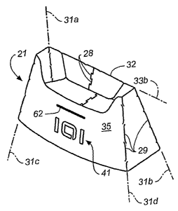
[00261 Turning to FIGS. 1 and 2, a business card holder, generally designated
21, is
shown which has been folded from a piece of flat sheet material and is ready
for use.
In FIG. 2, a plurality of business cards 22 are held by cardholder 21, as it
would
normally be used. Cardholder 21 has been folded from a flat sheet of material
or
cardholder blank 23, in this case a stainless steel blank, which sheet is
shown in FIG.
3. Once folded up into the three-dimensional structure of FIGS. 1 and 2, the
sheet has
been secured along edges, as will be described in more detail hereinafter,
against
unfolding.
[00271 Sheet 23 is shown in FIG. 3 as it would be typically formed out of a
much
larger sheet, for example, by laser cutting, water jet cutting, punching,
stamping
and/or other suitable means. Typically, a plurality of cardholder sheets 23
are laid out
in relatively nested relation to minimize scrap and then are cut from the
larger sheet,
4815-1939-2256\1
CA 02598086 2007-08-16
WO 2006/089090 PCT/US2006/005589
-8-
for example, by a CNC controlled laser cutter. Cardholder 21 is then formed by
folding cardholder blank 23, as will be described.
[00281 In FIG. 3 a generally U-shaped cardholder blank 23 is shown which has
free
edges 26 and 27 that have been formed with joinder structures 28, in this case
dovetail
configurations. One will appreciate that other joinder structures may also be
employed. Joinder structures 28 are formed in a manner which will allow the
spaced-
apart free edges 26 and 27 to eventually be joined together into the three-
dimensional
object of FIGS. 1 and 2. Cardholder blank 23 has edges 26 and 27 which are to
be
joined aiid are spaced apart from each other when the sheet material is in the
flat
condition of FIG. 3. The edge joining techniques of the present invention also
can be
used, however, to join edges which are contiguous or abutting relation when
sheet 23
is in the flat condition, for example, edges oriented at 90 degrees to each
other and
touching at an apex. Such edge configurations often are employed in corner
structures.
f00291 Additionally, cardholder 21 is a forxn of enclosure or continuous
peripheral
wall in wliich one edge 26 of the blank is folded around to produce a
continuous wall
which is joined to the other edge 27. The three-dimensioned structure produced
and
joined into a stable structure by the edge joining apparatus and method of the
present
invention does not have to be an enclosure or to have a continuous wall which
encircles a central space, but such structures are particularly advantageously
formed
by the present invention.
[003ol The flat sheet or cardholder blank 23 also includes a plurality of
shaped-
controlling folding structures 29 formed in the sheet of material along a
plurality of
desired fold lines 31a, 31b, 31c and 31d which will cause the sheet of
material to be
folded into a desired three-dimensional shape in which sheet edges 26 and 27
will be
positioned in juxtaposed registered relation. This folding process will be
described in
greater detail in connection with FIGS. 4-9.
4815-1939-2256\1
CA 02598086 2007-08-16
WO 2006/089090 PCT/US2006/005589
-9-
[003i1 Sheet 23 is further provided with at least one retention structure
formed to
retain the joinder structures 28 together against separation. In the
embodiment shown
in FIG. 3, the retention structures 32 are in the form of folds or bends along
retention
fold lines 33a and 33b that secure the folded cardholder blank against
unfolding.
[00321 The shape-controlling folding structures 29 and the retention folding
structures
32 are both preferably constructed in the same manner. These folding
structures are
provided as described in the Related Applications, and they are formed in a
manner
which will result in very precise folding of sheet material 23 along the
desired fold
lines. These folding structures can take the form of slits, grooves or
displacements
formed in cardholder blank 23, and they define folding straps 34 between
longitudinally adjacent fold inducing structures 29 and 32. Folding straps 34
between
the slits, grooves or displacements have center lines which extend obliquely
across
folding lines 31a-31d and 33a-33b so as to precisely control folding of sheet
blanks
23. In the most preferred form, the folding structures are formed with a kerf
or width
dimension that ensures that the sheet material on opposite sides of folding
structures
29 and 32 will engage in edge-to-face engagement during folding for greater
precision
of folding, when combined with the precision achieved by using oblique folding
straps 34. The principles which control precise sheet material folding are set
forth in
more detail, for example, in application U.S. Patent Application No.
10/256,870,
identified more fully in the Related Application section of this application.
[0033] Referring now to FIGS. 4-9, folding of cardholder blank 23 into the
three-
dimensional cardholder of FIGS. 1-2 can be described in more detail. In FIG.
4,
cardholder blank or sheet 23 has been folded along fold lines 31a and 3lb
upwardly
from the plane of the sheet in FIG. 3. Edges 26 and 27, with their joinder
structures
28, are now in a near vertical orientation.
[00341 In FIG. 5, one side of blank 23 has been folded along fold line 31d to
a near
parallel orientation to the front panel 35, which bears an "101" standing for
"Industrial
Origami, Inc." The fold along fold line 31d of FIG. 5, therefore, starts to
complete
4815-1939-2256\1
CA 02598086 2007-08-16
WO 2006/089090 PCT/US2006/005589
-10-
the enclosure which will result in edges 26 and 27 being juxtaposed, but edge
27 will
be seen in FIG. 5 not to be in position for joinder to edge 26.
[00351 In FIG. 6, a fold along fold line 31c has been made so as to position
edges 26
and 27 of the sheet in juxtaposed and registered relation with dovetail
joinder
structures 28 interengaged with each other so as to join what was the free
edges of the
sheet or blank 23 together.
[0036] Once back panel portions 42a and 42b have been folded together, they
will be
aligned in substantially the same plane, as will joinder dovetails 28 on edges
26 and
27. Such positioning of the dovetail joinder structures in the same plane
allows edges
26 and 27 to be slightly displaced inwardly or outwardly of the common plane
and
then displaced back into the common plane of panels 42a and 42b for
interlocking of
the dovetails. As long as the dovetails remain in a common plane, they will
not be
separable, as is well know to those skilled in the art.
[00371 It is possible for back panels 42a and 42b to be oriented in slightly
skewed
planes and still stay interlocked, with the amount of skewing which is
possible
increasing as the thickness of the sheet of material and the dimensional
tolerances of
the dovetails are increased. In fact, as will be described below, both front
panel 35
and back panels 42a, 42b are preferably bowed somewhat, from a common plane,
which can be easily accommodated by the thickness of the sheet stock and even
moderate differences in the dovetail dimensions.
[00381 It also should be noted that in the broadest aspect of the present
invention,
joinder structures 28 do not have to be formed for joining in substantially
two
dimensions, as are dovetails. Corner joinder structures can be provided, for
example,
in which the edge joinder structures prevent separation of the edges when
folded
together to produce a corner. A sheet retention structure must also be
appropriately
formed to prevent separation of the corner joinder structures from one
another.
Retention of the dovetails against separation is described below for joinder
structures
28.
4815-1939-2256\1
CA 02598086 2007-08-16
WO 2006/089090 PCT/US2006/005589
-11-
[0039j One advantage of the edge joinder method of the present invention is
that the
edges do not have to be overlapped, that is, the ends or edges of the sheet
material are
joined in end-to-end relation with the joined wall having the same thickness
across the
joined edges. For example, the edges of the sheet material lay "in-plane" with
respect
to one another and are not overlapped, that is, the edges do not lie one upon
the other.
This has both aesthetic and structural advantages for certain objects, such
as, business
card holders.
[004ol Edge joinder structures 28 are shown in the embodiment of FIGS. 1-9 as
being
substantially continuously extending along edges 26 aiid 27. It will be
understood,
however, that a single joinder structure 28 might be usable for joining edges
in some
structures, or intermittent, spaced-apart joinder structures 28 could be
employed. For
many structures, a continuous joint between edges 26 and 27 has strength, as
well as
aesthetic advantages.
[0041] At this point it also should be noted that FIGS. 1-9 do not show the
thickness
dimension of sheet or blank 23, and to that extent the drawings are schematic.
In fact,
sheet 23 will have a thickness dimension and when dovetail joinder structures
28 are
interengaged as shown in FIG. 6, the thickness dimension of the sheet will
prevent
separation of both the dovetails and free edges 26 and 27, as above described.
[00421 The structure of FIG. 6, which is essentially an enclosure which could
be part
of a rectangular box beam, a tapered box beam or the like, could be subjected
to
shifting of edges 26 and 27 out of the substantially common plane 42a, 42b,
with the
result of possible disengagement of dovetail joinder structures 28. Folding
structures
29, 32 have an advantage, in addition to precision of their folding, of being
able to
fold under relatively low folding forces. Thus, a stainless steel sheet can be
folded
along fold lines 31a-31d by hand. Juxtaposed free edges 26 and 27, therefore,
also
could become unfolded or even unfolded back to a flat sheet, as shown in FIG.
3.
Thus, it is preferable that at least one retention structure be provided on
blank 32 to
essentially interlock dovetails 28 against disengagement. In the broadest
sense that
could be a panel (not shown) that folds across the joinder dovetails and is
secured by a
4815-1939-2256\1
CA 02598086 2007-08-16
WO 2006/089090 PCT/US2006/005589
-12-
standard fastener such as a screw or rivet. This would increase the number of
parts
required for the cardholder, as well as creating an overlapping of walls.
[0043] In the embodiment shown in FIGS. 1-9, two retention fold lines 33a and
33b
are used to interlock dovetails 28 against separation. As will be seen in FIG.
7,
therefore, sheet flaps 51 and 52 have been folded down along fold line 33a to
a
position proximate front panel 35 bearing logo 41. In addition, blank flaps 53
and 54,
which also are held together by dovetails 28, have been folded down about
retention
fold line 33b, as shown in FIG. 9. The retention folds, therefore, cause flaps
51-54 to
be out of the common plane 42a, 42b of the back of the cardholder, and they
thereby
interlock the dovetails together against separation by virtue of flaps 53 and
54 limiting
out-of-plane motion of common plane portions 42a and 42b.
[0044] The retention fold lines 33a and 33b result in folds which are
extremely
difficult for even the relatively easily folded sheet material to unfold back
thereby
reducing the possibility that the dovetails will become disengaged.
[00451 In order to further enhance the interlocking of dovetail joinder
structures 28,
however, a keeper assembly further can be provided in cardholder blank 23
which is
adapted to resist unfolding of the sheet material along the retention fold
lines. In the
embodiment of FIGS. 1-9, the keeper assembly is comprised of a tab and a
mating
slot. In this case the tab takes the form of a first tab 61a on panel 51 and a
second tab
61b on panel 52, as shown in FIG. 1, that are dimensioned to be inserted into
a slot 62
in front panel 35 of sheet 23. The insertion of tabs 61a and 61b into slot 62
can best
be seen in FIG. 8. Thus, the slot and tab keeper assembly prevents panels 51
and 52
from unfolding along retention fold line 33a. Most preferably the length
dimension
between fold line 33a and tabs 61a, 61b is selected to cause a slight bowing
out of
front panel 35 and back panels 42a, 42b during the insertion process. This
bowing
causes a resilient springing back of the front and back panels toward each
other,
thereby preventing the tabs 61a, 61b from being easily able to escape from
slot 62.
4815-1939-2256\1
CA 02598086 2007-08-16
WO 2006/089090 PCT/US2006/005589
-13-
[00461 In FIG. 9, panels 53 and 54 have not been folded completely down about
retention fold line 33b to the final condition as shown in FIG. 1. Such
folding can
proceed until the panels 53 and 54 are at a slight angle to the back of the
cardholder so
as to support the cards 22 in a slightly tilted back condition. This makes it
easier to
remove the cards from the cardholder, and the panels 53 and 54 perform the
double
function of retaining the free edges of the sheet interlocked by joinder
structures 28
and structurally supporting cards 22 when positioned in the cardholder.
[00471 It should be noted that the fold along retention fold line 33b is one
in which
the sheet is almost folded back on itself. This can be readily done using the
technology of the Related Applications and it makes unfolding of the structure
even
more difficult, which is, of course, the purpose of the retention structures.
[00481 In the embodiment of FIGS. 1-9, joinder structures on the edges 26 and
27 are
provided by dovetails. In FIG. 10, free edges 26a and 27a are joined by L-
shaped
joinder structures 28a. It will be understood, therefore that various other
types of
interlocking joinder structures are contemplated for use in the present
invention. The
high precision with which such joinder structures can be folded during
relatively
complex folding of sheet 23, with fold lines at various angles to achieve the
desired
shape, makes it possible for very precise registration of the free edges of
the sheet.
[0049] In one embodinient illustrated in FIGS. 11 and 12, another retention
structure
which is capable of retaining mated joinder structures together against
separation. In
FIGS. 11 and 12, a plurality of side-by-side enclosure or housing blanks 124
are
formed in strip material 123. The enclosures are formed to receive a component
or
components, such as, electrical components 125a and 125b, and in the
illustrated
process, components 125a, 125b are mounted one after another into the side-by-
side
enclosure blanks 124 formed in strip 123. The enclosure blanks are further
formed
for folding after the components are positioned in the blank to complete the
enclosure.
Edge-joining joinder structures 128 are provided in blanks 124, and the
joinder
structures are held in interlocked relation by an alternative embodiment of a
retention
structure. The sequence illustrated is a staged mounting of components to the
side-
4815-1939-2256\1
CA 02598086 2007-08-16
WO 2006/089090 PCT/US2006/005589
-14-
by-side housing blanks and thereafter completion of the component enclosures
and
removal of the same from the strip.
[005ol Referring to FIG. 11 in more detail, therefore, a strip 123 is provided
in which
a plurality of side-by-side enclosure blanks 124 have been formed, for
example, by
laser cutting, water jet cutting, stamping, punching, and/or other suitable
means.
Initially, the blanks 124 would be in a flat condition or all in the same
plane. As
shown in FIG. 11, edges 126 and 127 of the blanks have been tilted up by about
90
degrees from the plane of sheet 123, and these edges will be seen to be fomled
with
joinder structures 128, which are again illustrated as dovetails. The sheet is
schematically illustrated in that it does not include a width dimension for
ease of
understanding. The upstanding sides 129 and 131 of blanks 124 are positioned
for
receipt of component 125a, 125b. A first component portion 125a is inserted
into the
partially formed enclosure blanks 124 at station 135. In the embodiment
illustrated, a
second component portion 125b can be mounted on the end of component 125a,
while
the component blank side walls 129 and 131 are in a near vertical orientation,
at
station 140. At station 145, side walls 129 and 131 are folded to begin to
enclose
component 125a, 125b, and at station 150 the enclosure is completed and
dovetails
128 shown in interlocked interengagement. At station 155, the enclosed
component
125a, 125b has been removed from sheet 123.
[00511 Again, there is a possible issue of unfolding of the enclosure blank
from
around component 125 a, 125b, and in the embodiment of FIGS. 11 and 12,
retention
of interlocking of dovetails 128 has been accomplished in a different manner
than for
the dovetails 28 of the embodiment of FIGS. 1-9.
(00521 FIG. 12 schematically illustrates the manner of retaining joinder
structures 128
togetlier that has been employed in the embodiment of FIGS. 11 and 12. As will
be
seen in FIG. 12, the upstanding side walls 129 and 131 essentially form an L-
shaped
end cross section with walls 139 and 141, respectively.
4815-1939-2256\1
CA 02598086 2007-08-16
WO 2006/089090 PCT/US2006/005589
-15-
[00531 The retention structure employed in the embodiment of FIGS. 11 and 12
is a
deformation which is here shown as L-shaped corners or bends 161 between
enclosure blank walls 129 and 139 and between walls 131 and 141, as shown in
FIG.
12. Corn.ers 161 are formed using conventional metal bending techniques; they
are
not folded or bent using the technology of the Related Applications. Thus, at
a station
or stage 130, L-shaped bends 161 are formed by a combination of conventional
bending dies that will require substantial force to be applied to form bends
or corners
161. The result is a bend or corner 161 which will hold its shape against
unbending.
Enclosure side wall 131 is joined to side wall 141 by a corner that
resiliently couples
the two side walls together. Small arcuate displacements of side wall 131
relative to
side wall 141, therefore, will be resisted by bend 161, and when the
displacing force is
removed, the side walls will return to the relative angular relationship
produced by
deforming them to station or stage 130.
[00541 The folds or corners 162 between enclosure blank side walls 139 and
enclosure blank back wall 163, and between enclosure blank side wall 141 and
back
wall 163 are made using the technology of the Related Applications. Folds 162,
therefore, are much more easily made, and they tend to resiliently spring back
or have
memory to a much lesser degree than bends 161. Standard or conventional metal
bending becomes very difficult as shapes become complex, so it is preferable
to
minimize the use of reliant folds, such as corners 161, and use folds, such as
folds
162, for as many of the enclosure forming folds as possible.
[00551 Once component 125a, 125b is mounted to the enclosure blank at stations
135,
140, folds 162 can be bent into the closed condition shown at stations 145 and
150.
The result will be that dovetails 128 will be interlocked, and the
conventional bends
or deformations of the enclosure blank at folds 161 will act as resilient
springs or
retention structures that resist unfolding of blanks 124. The angle to which
conventional corners or folds 161 are bent can be slightly less than 90
degrees so that
a resilient downward biasing of sides 129 and 131 toward component 125a, 125b
is
maintained. This will cooperate with folding of the sides 129, 131 into
abutting
4815-1939-2256\1
CA 02598086 2007-08-16
WO 2006/089090 PCT/US2006/005589
-16-
relation against the enclosed electronic component to keep the dovetail
joinder
structures from opening up or becoming separated.
[00561 As will be seen from FIG. 11 and 12, a process for assembly of
components
into a plurality of enclosures also can be implemented by using the edge
joining
techniques described above. Moreover, this process allows components to be
enclosed using a single sheet of material and without using separate
fasteners.
[00571 A sheet or strip of sheet material 123 is formed witli a plurality of
side-by-side
enclosure blaiiks 124. These blanks are preferably attached to a common sheet
or
strip 123 which can be moved through a plurality of assembly stages, 130, 135,
140,
145, 150 and 155. The enclosure blank as formed with a plurality of shape-
controlling folding structures, such as slits, grooves or displacements, and
side edges
126 and 127 of the enclosure blank, are formed with joinder structures
therein, such as
dovetails 128. A retention structure, such as a deformation or conventionally
formed
fold 161 is formed in blanks 124 at an early assembly station or stage, such
as stage
130, to provide a corner or bend that will resiliently return to its bent
shape to provide
a biasing structure. The process also includes the steps of folding the
enclosure blank
124 to produce a partially formed enclosure blank; mounting a component or
components in the partially formed enclosure blank; thereafter folding the
blank to
complete the enclosure and position the dovetail joinder structures in
interengagement; and retaining or securing the joinder against separation by,
for
example, a resilient biasing corner, bend or deformation.
[oo581 The foregoing description of specific embodiments of the present
invention
have been presented for purposes of illustration and description. They are not
intended to be exhaustive or to limit the invention to the precise forms
disclosed, and
obviously many modifications and variations are possible in light of the above
teaching. The embodiments were chosen and described in order to best explain
the
principles of the invention and its practical application in order to thereby
enable
others skilled in the art to best utilize the invention and the various
embodiments with
various modifications as are suited to the particular use contemplated. It is
intended
4815-1939-2256\1
CA 02598086 2007-08-16
WO 2006/089090 PCT/US2006/005589
-17-
that the scope of the invention be defined by the claims appended hereto and
their
equivalents.
4815-1939-2256\1