Note: Descriptions are shown in the official language in which they were submitted.
CA 02598149 2007-08-15
WO 2006/093803 PCT/US2006/006458
FLUSH MOUNTED ASSEMBLY FOR HOUSING AN AMBIENT AIR ABNORMAL
CONDITION SENSOR MODULE
Summary of the Invention
[0001] This invention is directed to an assembly for housing an electronic or
electro-mechanical module which assembly can be flush mounted in a wall,
partition, ceiling
or other structural member having a suitable mounting surface. These
commercially available
modules include coiuponents mounted on a circuit board and are designed for
specific
purposes. Some are designed to detect and warn of abnormal ambient air
conditions such as
fire, smoke, carbon monoxide or radon gas by providing audio or visual alarms.
Others are
designed to perform such functions as stand alone speaker strobes, speakers,
strobes, motion
detectors and exit signs and other life safety devices or to regulate ambient
conditions such as
thermostats and humidity regulators. All of the aforementioned modules and
other similar
types may be housed in the assembly of this invention.
[0002] The assembly of this invention is suitable to house modules which need
to
be connected to power and signaling wires as well as modules which are powered
by self
contained sources of electrical power such as batteries and modules which
require power
wiring and batteries as a back up source of electrical power.
[0003] The assembly of this invention permits the.flush or nearly flush
mounting of
the aforementioned modules in walls, partitions, ceilings and other structural
members built
of conventional material such as plaster, plasterboard, acoustical tile,
plastic, wood, metal or
paneling.
[0004] The assembly of this invention when used to house a smoke, fire or
carbon
monoxide detector module also complies with the requirements of building and
safety codes
CA 02598149 2007-08-15
WO 2006/093803 PCT/US2006/006458
concerned with the protection of electrical power wiring, ease of battery
replacement and
testing of the alarm.
[0005] The assembly of this invention provides a base that can be inserted
into an
opening in a wall or ceiling of a structure and taped into place for flush or
near flush
mounting. The base is sized to receive electronic and electro-mechanical
modules of varying
sizes and depending upon the power supply required for the electronic or
electro-mechanical
module and the local building code may be installed independently or mounted
in a code
approved electrical junction box.
[0006] The asseinbly of this invention also includes a frame which fits into
and is
removably attached to and is supported by the base. The frame may be varied to
accommodate different electronic and electro-mechanical modules of the types
previously
described.
[0007] The assenlbly of this invention further includes a closure plate which
is
removably connected to the frame and can be customized to adapt to the
environment in
which it is installed in accordance with both functional and aesthetic
requirements.
[0008] Other objects and purposes of the invention will be found in the
following
specification, claims and drawings.
Brief Description of the Drawings
[0009] The invention is illustrated more or less diagrammatically in the
following
drawings wherein:
[0010] Fig. 1 is a plan view of a flush mounted assembly of this invention
installed
in a structural member, in this embodiment, a ceiling of a building;
[0011] Fig. 2 is a facing view of the assembly prior to its flush
installation;
[0012] Fig. 3 is a side elevational view ofthe assembly, of Fig. 1
2
CA 02598149 2007-08-15
WO 2006/093803 PCT/US2006/006458
[0013] Fig. 4 is a cross sectional view taken along line 4-4 of Fig. 2 with
some
components of the installed circuit board module eliminated for clarity of
illustration;
[0014] Fig. 5 is an exploded view of the assembly of this invention;
[0015] Fig. 6 is an exploded view of the frame and circuit board module of
this
invention; and
[0016] Fig. 7 is an underside view of the closure plate.
Desc]iption of The Preferred Embodiment
[0017] The flush mounted assembly of this embodiment of the invention is
intended
to house an electronic module of the type which detects abnonnal conditions
and has a
response means. It is shown in an einbodiment in which the module is a
photoelectric smoke
detector and its response means is an audible alarm mounted on a circuit
board. It should be
understood and appreciated that the descriptive term electronic module which
detects
abnormal conditions and has a response means also include other types of
electronic sensors
which can be substituted for the previously mentioned pliotoelectric sinoke
detector and
alarin. This embodiment includes the following components, nainely, a closure
plate 11, a
base 13, a frame 15 which encloses a circuit board electronic module 17 and an
electrical
junction box 19. These components will be described in detail in the following
detailed
description of the invention.
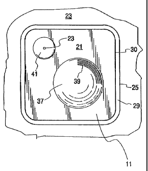
[0018] Fig. 1 of the drawings shows the assembly 2.1 of this invention flush
mounted in a ceiling 23 of a structure such as a building, vessel or vehicle.
The only visible
portion of the assembly 21 after installation is the closure plate 11 and the
outer edge 25 of
the peripheral side wal127 of the base 13. A narrow gap 29 is defined by the
spacing between
the peripheral edge 30 of the closure plate and the outer edge 25 of
the.peripheral side wall 27
of the base 13 and this gap opens into the interior 33 of the base 13 to
permit ambient air to
3
CA 02598149 2007-08-15
WO 2006/093803 PCT/US2006/006458
enter therein. As can be seen most clearly in Figs. 3 and 4 of the drawings,
the peripheral
edge 30 of the closure plate 11 is located to the front of the outer edge 25
of the peripheral
side wall 27 of the base. This arrangement facilitates the entry of waves of
heated air into the
interior 33 of the base 13.
[0019] The closure plate 11 shown in Fig. 7 of the drawings is generally
rectangular
in shape with rounded corners providing its peripheral edge 30 with a shape
similar to the
outer edge 25 of the base side wall 27. The closure plate is formed of a
suitable plastic or
otlier material with a slight heinispherical protrusion 37 on the front face
thereof. Formed in
the protrusion are a series of arcuate passages 391ocated in one quadrant of
the protrusion to
permit the passage of sound from the interior 33 of the base 13 to the
outside. A second and
smaller hemispherical protrusion 41 is also formed in the face of the closure
plate 11. A
small circular passage 43 is formed in the protrusion 41 and the passage
receives a light
transmitting test button 45 (see Fig. 4) which extends through this passage as
is conventional
in photoelectric smoke detectors and similar devices. The test button 45 is
formed integrally
with and at one end of a plastic arm 47 which is attached at its opposite end
to bosses 48
formed on the closure plate 11. An inwardly projecting protrusion 49 is also
formed
integrally with the plastic arm adjacent the test button 45 to engage a test
switch on the circuit
board module 17. Mounting fingers 51 extend from the inside surface of the
closure plate 11.
Tabs 53 are provided at the inner distal ends of the mounting fingers 51 and
these tabs engage
sloping tabs 55 (See Fig. 6) formed on fingers 57 extending from the frame 15.
The
mounting fmgers 51 both support the closure plate on the frame 15 and permit
its removal to
gain access to the interior 33 of the base 13 through rotation of the closure
plate and its
fingers relative to the sloping tabs 55 formed on the fingers 57 of the frame
15. The closure
plate 11 may be reinstalled by positioning its mounting fingers and tabs
adjacent the
4
CA 02598149 2007-08-15
WO 2006/093803 PCT/US2006/006458
mounting fingers and tabs of the frame 15 and rotating the closure plate
relative to the frarne
15 and to the base 13. It should be noted that the reinstallation of the
closure plate 11 is
facilitated by the provision of the sloping tabs 55 on the fingers 57 of the
frame 15. . When the
closure plate 11 is reinstalled, the tabs 53 of the mounting fingers 51 of the
closure plate are
aligned with the sloping tabs 55 and slight rotation of the closure plate
relative to the frame
and base inoves the tabs 53 down the slope of the tabs 55 and into engagement
therewith.
[0020] Radially extending upstanding ribs 59 are fonned on the inside surface
of
the closure plate 11 to direct ambient air entering the assembly 21 through
the narrow gap 29
to the sensor of the circuit board module 17.
[0021] The base 13 shown in detail in Figs. 4 and 5 is somewhat rectangular in
shape and is preferably formed of a suitable injection molded plastic but
other suitable
materials may also be used. The base includes a peripheral side wall 27 which
has an outer
facing edge 25. This wall has four sides and rounded corners. Formed
integrally with the
base 13 is an inner wall 71 which together with the peripheral wa1127 define a
shallow cavity
73. The shallow cavity forms the previously mentioned interior 33 of the base.
Also fom-ied
integrally with the peripheral side wal127 and the inner wa1171 of the base is
a laterally
outwardly projecting flange 75 which extends from the outer facing edge 25 of
the peripheral
side wal127 on all four sides of the peripheral wall. The flange 75 is
perforated with small
circular passages 77 over which drywall tape (not shown) and through which a
plastering
compound (called "mud") (also not shown) are applied when the flange is
positioned against
the outer facing surface of a structural surface in which the assembly 21 of
this invention is
installed. Staples, screws, nails or adhesive, none of which is shown, may be
used to fasten
the flange 75 to the outer surface of the structural surface before the
application of the dry
wall tape and mud.
CA 02598149 2007-08-15
WO 2006/093803 PCT/US2006/006458
[0022] An opening 79 is formed in the inner wall 71 of the base 13. The four
corners of the inner wall extend forward of the inner wall to form seats 81
for mounting on
the junction box 19 in a manner to be hereinafter described. Arcuate slots 83
are formed in
the seats 81 to receive fasteners to attach the base 13 to the junction box
19. An upstanding
interior wall 95 is formed integrally with inner wall 71 of the base 81 and is
located
outwardly of the arcuate slots 83 of the seats 81. The interior wal195 defines
a space to
receive and contain the frame 15. A pair of frame retaining fingers 97 are
formed in opposite
sides of the interior wa1195 and cooperate with a pair of lugs 99 formed on
the side of the
interior wall 95 connecting the opposite sides to secure the frame 15 in
position and to pennit
its easy installation and removal.
[0023] The frame 15 which is injection molded of a suitable plastic and
supports
and protects the circuit board module 17 is shown in Fig. 5 of the drawings in
relation to the
other components of the assembly 21 of this invention. In Fig. 6, it is shown
in an exploded
view. The frame includes a front component 111 and a rear component 113 which
are
releasably connected to each other to support and protect the circuit board
module 17. In this
embodiment, the rear component 113 snaps into the front component 111 and
captures the
outer edges of the circuit board module 17 therebetween. The outer dimensions
of the front
and rear components of the frame remain essentially constant for the various
types of modules
which are carried by the frame with the internal configurations of the
components varied in
accordance with the particular module installed.
[0024] hi this embodiment of the invention, the frame 15 is configured to
carry a
photoelectric smoke detector circuit board rnodule 17. To accommodate the
photoelectric
smoke detector, a circular passage 121 is formed in the front component 111 to
receive the
detector element 123 of the module 17. Also, a speaker housing 125 is molded
in the front
6
CA 02598149 2007-08-15
WO 2006/093803 PCT/US2006/006458
component 115 to receive a speaker 126 of the module 17. An LED 127 and a test
switch
128 are provided on the module 17. The switch 128 also functions as a silence
switch. Other
variations include a battery compartment cutaway 129 which receives a 9 volt
battery 131.
The battery coinpartment includes a battery compartment door 133 which is
mounted on the
front component 111 and a battery door latch 135 mounted on the rear frame
component 113.
Fasteners 137 are provided to securely connect the front and rear components
and the circuit
board module 17 together. Corresponding modifications can be made to the front
and rear
components of the frame 15 to accominodate otlzer types of modules.
[0025] The junction box 19 may be a conventional sheet metal, cast metal or
plastic
box of the type used to receive electrical wiring which conducts 110 V to 220
V/230V AC
power. In some jurisdictions, such a junction box is also required for lower
voltage signaling
and communication wires. The junction box 19 shown and described herein has
been
modified to accommodate the base 13 while meeting the code requirements for
both
conventional power wiring and signal and communication wiring. As is
conventional, what
are called punch out openings 141 are formed in the side walls 143 and in the
base wall 145
of the junction box. These openings can be punched out by an electrician to
permit power
wires (not shown) which may be in conduit or not depending upon local building
codes to be
extended into the junction box so as to be connected to circuit board module
17. This
connection between the power wires and the module is made by connector 147
shown in Fig.
5. The preferred junction box 19 shown most clearly in Figs. 4 and 5 of the
drawings is
modified by the addition of L-shaped brackets 151 to the four corners of the
junction box.
Each bracket has a leg '153 which is welded or otherwise fastened to the base
wall 145 of the
junction box and a second leg 155 which extends at right angles to its first
leg and has its
distal end welded to one of the side walls 143 of the junction box. The second
legs 145
7
CA 02598149 2007-08-15
WO 2006/093803 PCT/US2006/006458
engage the seats 81 of the base 13 and provide structures for receiving
fastening screws 157
to attach the base 13 to the junction box 11.
8