Note: Descriptions are shown in the official language in which they were submitted.
CA 02598214 2007-08-17
WO 2006/091382
PCT/US2006/004485
Valve Apparatus, System and Method
Field of the Invention
The present invention relates generally to apparatus, systems, and
methods for use in a lumen; and more particularly to a valve apparatus,
systems,
and methods for use in the vasculature system.
Background of the Invention
The venous system of the legs uses valves and muscles as part of the
body's pumping mechanism to return blood to the heart. Venous valves create
one way flow to prevent blood from flowing away from the heart. When valves
fail, blood can pool in the lower legs resulting in swelling and ulcers of the
leg.
The absence of functioning venous valves can lead to chronic venous
insufficiency.
Techniques for both repairing and replacing the valves exist, but are
tedious and require invasive surgical procedures. Direct and indirect
valvuoplasty procedures are used to repair damaged valves. Transposition and
transplantation are used to replace an incompetent valve. Transposition
involves
moving a vein with an incompetent valve to a site with a competent valve.
Transplantation replaces an incompetent valve with a harvested valve from
another venous site. Prosthetic valves can be transplanted into the venous
system, but current devices are not successful enough to see widespread usage.
Brief Description of the Drawings
Figs. 1A-1B illustrate an embodiment of a valve.
Fig. 1C illustrates a cross-sectional view of the valve illustrated in Fig.
lA taken along plane 1C-1C.
Fig. 1D illustrates a cross-sectional view of the valve illustrated in Fig.
1B taken along plane 1D-1D.
Figs. 2A-2D illustrate segment views of embodiments of a cover.
Figs. 3A-3B illustrate a valve in an expanded and a collapsed state.
1
CA 02598214 2007-08-17
WO 2006/091382
PCT/US2006/004485
Fig. 4 illustrates an embodiment of a system that includes a valve.
Fig. 5 illustrates an embodiment of a system that includes a valve.
Fig. 6 illustrates an embodiment of a system that includes a valve.
Detailed Description
Embodiments of the present invention are directed to an apparatus,
system, and method for valve replacement or augmentation. For example, the
apparatus can include a valve that can be used to replace or augment an
incompetent valve in a body lumen. Embodiments of the valve can include a
frame and cover that can be implanted through minimally-invasive techniques
into the body lumen. In one example, embodiments of the apparatus, system,
and method for valve replacement or augmentation may help to maintain
antegrade blood flow, while decreasing retrograde blood flow in a venous
system of individuals having venous insufficiency, such as venous
insufficiency
in the legs.
The figures herein follow a numbering convention in which the first digit
or digits correspond to the drawing figure number and the remaining digits
identify an element or component in the drawing. Similar elements or
components between different figures may be identified by the use of similar
digits. For example, 110 may reference element "10" in Fig. 1, and a similar
element may be referenced as 210 in Fig. 2. As will be appreciated, elements
shown in the various embodiments herein can be added, exchanged, and/or
eliminated so as to provide a number of additional embodiments of valve. In
addition, discussion of features and/or attributes for an element with respect
to
one Fig. can also apply to the element shown in one or more additional Figs.
Figs. 1A-1D and 3A-3B provide illustrations of various embodiments of
a valve of the present invention. Generally, the valve can be implanted within
the fluid passageway of a body lumen, such as for replacement or augmentation
of a valve structure within the body lumen (e.g., a venous valve). In one
embodiment, the valve of the present invention may be beneficial to regulate
the
flow of a bodily fluid through the body lumen in a single direction.
2
CA 02598214 2007-08-17
WO 2006/091382
PCT/US2006/004485
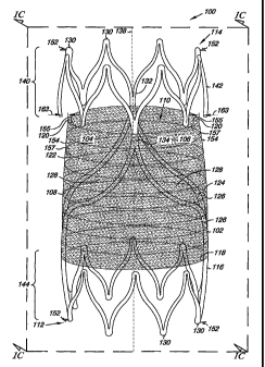
Figs. 1A-1D illustrate one embodiment of a venous valve 100. Venous
valve 100 includes a frame 102, a first leaflet 104 and a second leaflet 106
formed from a cover 108, where the frame 102 and the leaflets 104 and 106 can
resiliently radially collapse and expand, as will be discussed herein. Among
other things, the frame 102 and the leaflets 104 and 106 define a lumen 110 of
the valve 100. The lumen 110 allows for, among other things, fluid (e.g.,
blood)
to move through the valve 100.
The frame 102 also includes a first end 112 and a second end 114. The
first end 112 and the second end 114 define a length of the frame 102 and of
the
valve 100. In one embodiment, the length of valve 100 can have a number of
values. As will be appreciated, the length of valve 100 can be determined
based
upon the location into which the valve 100 is to be implanted. In other words,
the length of the valve 100 can be patient specific. Examples of values for
the
length include 4 millimeters to 30 millimeters.
The frame 102 further includes an outer surface 116 and an inner surface
118 opposite the outer surface 116. In one embodiment, the cover 108 can be
located over at least a portion of the outer surface 116 of the frame 102. For
example, the cover 108 can extend around a perimeter of the frame 102 so as to
cover the outer surface 116 of the frame 102. In other words, the cover 108
can
extend over the outer surface 116 of the frame 102 so as to limit, or
eliminate,
exposed portions of the outer surface 116 of the frame 102. In an additional
embodiment, the cover 108 can be located over at least a portion of the inner
surface 118 of the frame 102. A further embodiment includes the cover 108
located over at least a portion of the outer surface 116 and the inner surface
118.
The leaflets 104 and 106 further include surfaces defining a reversibly
sealable opening 120 for unidirectional flow of a liquid through the lumen 110
of
the valve 100. For example, the surfaces of the leaflets 104 and 106 can be
deflectable between a closed configuration in which fluid flow through the
lumen 110 can be restricted and an open configuration in which fluid flow
through the lumen 110 can be permitted.
The cover 108 further includes a physical configuration that provides
support to the shape and structure of the leaflets 104 and 106. As used
herein,
physical configurations that provide "support" can include structures and/or
3
CA 02598214 2007-08-17
WO 2006/091382
PCT/US2006/004485
members that are integrated into and/or a part of the material that composes
the
cover 108 that help to maintain a pre-implant shape and size of the leaflets
of the
valve.
The physical configuration that provides support to the leaflets 104 and
106 can be provided in a number of ways. For example, the cover 108 can
include a matrix 122 reinforced with flexible support members 124 to provide a
composite structure for the leaflets 104 and 106. The flexible support members
124 can be integrated into the matrix 122 so as to help prevent deformation of
the original size and shape of the leaflets 104 and 106 that may occur over
time
through such processes as material stretch, creep, and stress relaxation. So,
for
example, the integrated flexible support members 124 can be oriented to
provide
circumferential support to the first leaflet and the second leaflet 104 and
106.
In one embodiment, the cover 108 can have a multi-layer configuration
in which at least one layer of the integrated flexible support members 124 can
be
integrated and/or laminated between at least one layer of the matrix 122
material.
For example, as illustrated in Figs. 1A-1D, the cover 108 includes one or more
layers of the flexible support members 124 and one or more layers of the
matrix
122 that contribute to enhanced mechanical and handling properties of the
cover
108. As discussed herein, the layers of the flexible support members 124 can
be
positioned to lie in a number of different relationships to each other. For
example, the layers of the flexible support members 124 can lie in coplanar
relations to one another, where the layers can have a number of angular
relations
to one another (e.g., orthogonal relation to each other). Other configurations
are
also possible.
As illustrated, the leaflets 104 and 106 can also have an integrated
configuration in which the flexible support members 124 are positioned within
the matrix 122 material of the leaflets 104 and 106. Although the cover 108 is
illustrated as having the flexible support members 124 disposed substantially
in
the center of a cross section of the matrix 122, it is understood that the
flexible
support members 124 can be disposed at a number of locations within the cover
108.
In addition, different combinations of materials (discussed herein) can be
used for one or more of the flexible support members 124 and/or the matrix 122
4
CA 02598214 2007-08-17
WO 2006/091382
PCT/US2006/004485
material. For example, the flexible support members 124 of the same structure
and chemistry or different structures and chemistries can be overlaid on top
of
one another to and combined with the matrix 122 material to fabricate a cover
108 having the desired mechanical strength and physical properties. In an
additional embodiment, the cover 108 forming the leaflets 104 and 106 can have
a configuration in which the matrix 122 can be formed of a first material and
the
flexible support members 124 can be formed of a second material different than
the first material. For example, the leaflets 104 and 106 can include a top
layer
of the matrix 122 of the first material and a bottom layer of the matrix 122
of
first material coupled to the top layer of the first material. The flexible
support
members 124 of the leaflets 104 and 106 can then be positioned to lie between
the top and bottom layers of the first material. The matrix 122 can be
integrated
with the flexible support members 124 in such a way that the material of the
matrix 122 penetrates through openings between the flexible support members
124 to interlock the matrix 122 and the flexible support members 124. Surfaces
of adjacent layers of the matrix 122 material can also interlock with one
another,
regardless of whether the layers of the matrix 122 are separated by a layer of
the
flexible support members 124 or whether they are made from the same or
different materials.
In an additional embodiment, the flexible support members 124 can
include a number of forms that contribute to both the mechanical and handling
properties of the cover 108. Examples of such forms for the flexible support
members 124 include, but are not limited to, those selected from the group
consisting of weaves, braids, meshes, knits, warped knitted (i.e., lace-like),
matted, coils (continuous helically wound coils or individually positioned
coils),
rings, ribbons (individual or continuous), and non-woven structures including
electrostatically spun fibers or fiber compositions of polymers, polymers and
other materials such as various copolymers.
In addition, mechanical properties of the cover 108 can be altered by
changing the density, form, and/or texture of the flexible support members 124
in one or more locations of the cover 108. Examples of suitable structures
used
to create the flexible support members 124 can include, for example,
monofilaments, yarns, threads, braids, or bundles of fibers.
5
CA 02598214 2007-08-17
WO 2006/091382
PCT/US2006/004485
Regardless of its configuration, the composite structure of the cover 108
should possess a burst strength adequate to withstand pressures imposed by
blood moving in the circulation system. In addition, the cover 108 can be
sufficiently thin and pliable so as to permit radially-collapsing of the
leaflets 104
and 106 portion of the valve 100 to allow the valve 100 to provide the
reversibly
sealable opening 120 and for delivery by catheter to a location within a body
lumen. As discussed herein, different portions of the matrix 122 and/or the
flexible support members 124 may be made from different materials. Adequate
strength and physical properties are developed in the cover 108 through the
selection of materials used to form the matrix 122 and the flexible support
members 124, and the manufacturing process used to join them.
By way of example, both the matrix 122 and the flexible support
members 124 can be formed of a number of materials. For example, the matrix
122 and/or the flexible support members 124 can be formed of, by way of
illustration and not by limitation, thermoplastic and thermo-set polymers.
Examples of these polymers include polyolefins such as polyethylene and
polypropylene, polyesters such as Dacron, polyethylene terephthalate and
polybutylene terephthalate, vinyl halide polymers such as polyvinyl chloride
(PVC), polyvinylacetate such as ethyl vinyl acetate (EVA), polyurethanes,
polymethylmethacrylate, pellethane, polyamides such as nylon 4, nylon 6, nylon
66, nylon 610, nylon 11, nylon 12 and polycaprolactam, polyaramids (e.g.,
KEVLAR), polystyrene-polyisobutylene-polystyrene (SIBS), segmented
poly(carbonate-urethane), Rayon, fluoropolymers such as
polytetrafluoroethylene (PTFE or TFE) or expanded polytetrafluoroethylene
(ePTFE), ethylene-chlorofluoroethylene (ECTFE), fluorinated ethylene
propylene (FEP), polychlorotrifluoroethylene (PCTFE), polyvinylfluoride
(PVF), or polyvinylidenefluoride (PVDF), natural biopolymers such as
cellulose,
chitin, keratin, silk, and collagen, explanted veins, decellularized basement
membrane materials, submucosa materials such as small intestine submucosa
(SIS) or umbilical vein, or other naturally occurring extracellular matrix
(ECM),
and other autologous or allogeneic biological materials either treated by
crosslinking or not, and mixtures and copolymers thereof. SIS and ECM
materials can be autologous, allogeneic or xenograft material derived from
6
CA 02598214 2007-08-17
WO 2006/091382
PCT/US2006/004485
mammals, including source, such as human, cattle, sheep, and porcine. As will
be appreciated, blends or mixtures of two or more of the materials provided
herein are possible. For example, SIBS can be blended with one or more
basement membrane materials.
Each of the polymers noted herein may be used in conjunction with
radioopaque filler materials such as barium sulfate, bismuth trioxide, bismuth
carbonate, powdered tungsten, powdered tantalum, or the like so that the
location of the matrix 122 and/or the flexible support members 124 may be
radiographically visualized within the human body.
In another embodiment of the present invention, the polymers and blends
that are used to form the composite can be used as a drug delivery matrix. To
form this matrix, the polymer can be mixed with a therapeutic agent or the
agent
can be applied to the surface or otherwise delivered from the material. The
variety of different therapeutic agents that can be used in conjunction with
the
polymers of the present invention is vast. In general, therapeutic agents
which
may be administered via the pharmaceutical compositions of the invention
include, without limitation: antiinfectives such as antibiotics and antiviral
agents;
analgesics and analgesic combinations; anti-inflammatory agents; hormones
such as steroids; and naturally derived or genetically engineered proteins,
polysaccharides, glycoproteins, or lipoproteins, anti-thrombotic agents, anti
Pt
agents, anti-immunogenic agents, anti-mitotic agents, anti proliferative
agents,
and angiogenic agents. Matrix formulations may be formulated by mixing one
or more therapeutic agents with the polymer. The therapeutic agent may be
present as a liquid, a finely divided solid, or any other appropriate physical
form.
Typically, but optionally, the matrix will include one or more additives, such
as
diluents, carriers, excipients, stabilizers or the like. Additionally,
radioopaque
markers may be added to the composite to allow imaging of the composite after
implantation.
In an additional embodiment, the flexible support members 124 can be
= 30 formed of ceramics, and/or metals. Suitable ceramics for the flexible
support
members 124 include those formed from basalt (solidified volcanic lava), and
sold under the trade identifier "Sudaglass." In one embodiment, the basalt can
be mechanically crushed to provide the basalt in a fibrous form having a
7
CA 02598214 2007-08-17
WO 2006/091382
PCT/US2006/004485
predetermined size of 9 to 17 microns in length. The basalt in the fibrous
form
can be blended with one or more of the polymers noted herein (e.g., SIBS, or
polyolefins) so as to distribute the basalt in the fibrous form through the
polymer
matrix. In one embodiment, the basalt polymer composite can include 0.1
percent (wt.) basalt in the fibrous form. As will be appreciated, other weight
percentage of basalt in the fibrous form relative polymer are possible.
The flexible support members 124 can also be formed of other
nanostructures, such as carbon nanotubules. For example, carbon nano-tubules
can be blended with one or more of the polymers noted herein (e.g., SIBS) so
as
to distribute the carbon nano-tubules through the polymer matrix. In one
embodiment, the carbon nano-tubule polymer composite can include from 0.1
percent to 20 percent (wt.) carbon nano-tubules. As will be appreciated, other
weight percentage of carbon nano-tubules relative polymer are possible.
The flexible support members 124 can also be formed of metals and/or
metal alloys. For example, suitable metals and/or metal alloys for the
flexible
support members 124 include, but are not limited to, medical grade stainless
steels (304, 306, 308, 316L, 318, etc.), gold, platinum, platinum alloys,
palladium, rhodium, tungsten, tungsten alloys, cobalt chrome, titanium and
titanium alloys, and other metal alloys such as those composed of
titanium/nickel and sold under the trade identifier "Nitinol."
Heat treatment of the Nitinol alloy may also be desirable. An example of
such a heat treatment includes, but is not limited to, placing the Nitinol in
its
desired shape onto a mandrel. The Nitinol is then heated to a temperature of
650 -750 F. for a predetermined time (e.g., two (2) to five (5) minutes),
possibly (but not necessarily) annealing the constituent Nitinol. After heat
treatment, the flexible support members 124 retain their shape and the Nitinol
alloy retains its super-elastic properties.
The support members 124 can also include a variety of cross-sectional
configurations. For example, the support members 124 can have one or more of
a round (e.g., circular, oval, and/or elliptical), "ribbon" configuration with
rectangular geometries with an aspect ratio of at least 0.5 (thickness/width)
having perpendicular sides, one or more convex sides, or one or more concave
8
CA 02598214 2007-08-17
WO 2006/091382
PCT/US2006/004485
sides; semi-circular; triangular; tubular; I-shaped; T-shaped; and
trapezoidal.
Theses embodiment, however, are not limited to the present examples as other
cross-sectional geometries are also possible. With respect to "braid," the
term
can include tubular constructions in which the flexible support members 124
making up the construction are woven radially in an in-and-out fashion as they
cross to form a tubular member defining a single lumen. The braid can also be
constructed of flexible support members 124 of different widths. Changes in
the
braid can allow for pocket formation and the shape of the leaflets 104 and
106,
as discussed herein. Such pocket formation can allow the valve leaflet, in one
embodiment, to not assume an absolutely planar or cylindrical shape but
instead
form a pocket or cupped depression that is more efficient at forming a seal
between the two leaflets. This rounded shape adjacent the sinus region of the
valve cusp can help allow the valve cusp to be rinsed by blood as the leaflet
closes.
Figs. 2A-2D illustrate embodiments for a variety of configurations for
the cover 208. The embodiments illustrated in Figs. 2A-2D are segment views
(i.e., partial views) used to provide a non-limiting illustration of different
configurations of the matrix 222 and the flexible support members 224 used in
the cover 208. For example, Fig. 2A illustrates an embodiment in which the
matrix 122 includes a first layer 201 and a second layer 203 of material
positioned around the flexible support members 224. As illustrated in Fig. 2A,
the flexible support members 224 have a knit configuration.
In an additional embodiment, Fig. 2B illustrates an embodiment in which
the matrix 222 includes the first layer 201 and the second layer 203 of
material
positioned around a first course 205 of the flexible support members 224. The
embodiment illustrated in Fig. 2B further includes a second course 207 of the
flexible support members 224 positioned between the second layer 203 and a
third layer 209 of the matrix 222. As illustrated, the first course 205 and
the
second course 207 of the flexible support members 224 in Fig. 2b have a woven
configuration. As will be appreciated, different configurations of the
flexible
support members 224 (e.g., one flexible support member course having a knit
configuration and one flexible support member course having a coil
configuration) could be combined in the cover 204.
9
CA 02598214 2007-08-17
WO 2006/091382
PCT/US2006/004485
Fig. 2C illustrates another embodiment of the cover 208 that includes the
matrix 222 surrounding the flexible support members 224 in a continuous
helically wound coil configuration. As will be appreciated, the layers of the
matrix 122 material can have all, some or none of the layers of the same or
chemical composition. Similarly, the flexible support members 224 can have
same or different configuration and/or chemical composition. In addition,
mechanical properties of the cover 208 can be altered by changing the density,
form, and/or texture of the flexible support members 224.
Fig. 2D illustrates another embodiment of the cover 208 that includes the
matrix 222 that includes a distribution of the flexible support members 224.
In
one embodiment, the distribution of the flexible support members 224 can
include a distribution of the nanostructures (e.g., basalt, and/or carbon
nanotubules), as discussed herein. As will be appreciated, the layers of the
matrix 122 material can have all, some or none of the layers of the same or
chemical composition. Similarly, the flexible support members 224 can have
same or different configuration and/or chemical composition. In addition,
mechanical properties of the cover 208 can be altered by changing the density,
form, and/or texture of the flexible support members 224.
Referring again to Figs. 1A-1D, the fibers used in the flexible support
members 124 may be made using a variety of processes that provide fibers with
the desired properties (such as modulus, tensile strength, elongation etc.).
Those
skilled in the art of fiber processing are well versed in the art of
extrusion, paste
extrusion and stretching, solution spinning, electrostatic spinning, along
with
other fiber processing techniques, which may be used to provide polymer based
fibers. These fibers may be oriented or drawn using conventional process to
provide the desired degree of modulus, strength, and elongation. Generally, a
fiber orientation process is used to improve the properties of the reinforcing
fibers. The fibers can be oriented using a variety of drawing technologies
such
as single, multiple or continuous drawing steps with or without heating zones
and/or relaxation. Additionally, these fibers may be post treated with various
annealing, scouring, coating or surface treatment steps.
As will be appreciated, the cover 108 can be formed in any number of
ways. For example, the embodiments of the cover 108 can be made by injecting,
CA 02598214 2007-08-17
WO 2006/091382
PCT/US2006/004485
pouring, casting, or otherwise placing the matrix 122 material (e.g., a
polymer
solution) into a mold set-up comprised of a mold and the flexible support
members 124. Alternatively, the embodiments of the cover 108 can be made by
blending, or mixing, the matrix 122 material (e.g., a polymer) with flexible
support members 124 (e.g., the carbon nano-tubules, or fibrous Basalt) before
or
during the injecting, pouring, or casting process into the mold.
The general processing steps include the selection of the materials from
which the matrix 122 and the flexible support members 124 are made. In one
embodiment, the cover 108 can generally be formed by use of compression
molding in the mold set-up under a dry inert environment (for example, under
nitrogen and/or argon) or under vacuum, at high enough temperatures,
pressures,
and long enough residence times (with proper cooling) to consolidate the
composite. Alternately, the cover 108 composite can be formed by use of an
autoclave, under a dry inert environment or under vacuum, at high enough
temperatures and long enough residence times to consolidate the composite.
Proper consolidation condition should provide a composite with no voids
therein.
The flexible support members 124 are generally ceramic and/or
polymeric (e.g., semi-crystalline polymers) while the matrix 122 materials are
generally either amorphous or semi-crystalline polymers. In conventional
composites, such as glass or carbon reinforced composites, the flexible
support
members 124 are not affected by consolidation temperature of the matrix 122.
In addition, some or all of the fibers of the flexible support members 124 can
be
restrained during the consolidation process. The flexible support members 124
can be restrained during the heat treatment or the consolidation in a variety
of
ways, including, but not limited to, mechanical clamps or rack systems. This
allows a reduction or a minimization in relaxation of fiber orientation.
Additionally restraining the flexible support members 124 Will control or
avoid
shrinkage of the flexible support members 124 during heat treatment and/or
consolidation.
In an alternative embodiment, the matrix 122 material can be extruded or
formed into a tubing of appropriate size and thickness. The material of the
matrix 122 can then be cross-linked to raise the melt temperature of the
resulting
11
CA 02598214 2007-08-17
WO 2006/091382
PCT/US2006/004485
tube. The tube can then inflated and stretched to give the included polymer a
specific molecular orientation. The tube of the matrix 122 material can then
be
placed over the combination of an inner layer of the matrix 122 material and
the
flexible support members 124 and the material of the matrix 122 heat-shrunk
around the flexible support members 124. Alternatively, the flexible support
members 124 can be dipped into molten material of the matrix 122 to form the
cover 108. In yet another embodiment, suitable adhesive for the selected
materials can be used to bond the matrix 122 material to additional layers of
the
matrix 122 material and to layers of the flexible support members 124. In an
additional embodiment, the matrix 122 can be co-processed with the flexible
support members 124 (e.g., nanostructures or fibrous basalt) so as to
distribute
the flexible support members 124 through the matrix 122.
In addition to the cover 108, the frame 102 too can be formed from a
wide variety of materials and in a wide variety of configurations. Generally,
frame 102 can have a unitary structure with an open frame configuration. For
example, the open frame configuration can include frame members 126 that
define openings 128 across the frame 102 through which valve leaflets 104 and
106 formed by the cover 108 can radially-collapse and radially-expand, as will
be described herein.
In addition, the first end 112 and the second end 114 each include a
plurality of end portions 130 that lay on a common plane. The plurality of end
portions 130, however, need not all lay on the common plane. In other words,
it
is possible that one or more of the end portions 130 of the frame 102 lay
above
and/or below the common plane.
While the frames illustrated herein, for example frame 102, are shown as
having a circular configuration, other configurations are also possible. For
example, the frame 102 could have an elliptical configuration. As such, the
present invention should not be limited to the illustration of the frames,
such as
frame 102, provided herein.
As illustrated in Figs. 1A-1D, the frame 102 can further include a first
leaflet connection region 132 and a second leaflet connection region 134
adjacent the second end 114 of the frame 102. In the present example, the
cover
108 can be coupled, as described more fully herein, to at least the first
leaflet
12
CA 02598214 2007-08-17
WO 2006/091382
PCT/US2006/004485
connection region 132 and the second leaflet connection region 134. The cover
108 so coupled can then move (e.g., pivot) relative the first leaflet
connection
region 132 and the second leaflet connection region 134 between an open valve
configuration (illustrated in Figs. 1A and 1C) and a closed valve
configuration
(illustrated in Figs. 1B and 1D). As illustrated in the closed valve
configuration
(Figs. 1B and 1D), the open frame configuration of frame 102 allows cover 108
to move through the openings 128 in creating the reversible sealable opening
120 of the valve 100.
As illustrated in Figs. 1A-1D, the first leaflet connection region 132 and
the second leaflet connection region 134 can be positioned opposite each other
along a common axis. In addition, the first leaflet connection region 132 and
the
second leaflet connection region 134 can be radially symmetric around a
longitudinal central axis 138 of the frame 102. As illustrated, the first
leaflet
connection region 132 and the second leaflet connection region 134 can be
positioned approximately one hundred eighty (180) degrees relative each other
around the longitudinal central axis 138 of the frame 102. As will be
appreciated, the first leaflet connection region 132 and the second leaflet
connection region 134 need not necessarily display an equally spaced
symmetrical relationship as described above in order to practice the
embodiments of the present invention. For example, the radial relationship can
have the first leaflet connection region 132 and the second leaflet connection
region 134 positioned at values greater than one hundred eighty (180) degrees
and less than one hundred eighty (180) degrees relative each other around the
longitudinal central axis 138 of the frame 102.
The frame 102 can have similar and/or different cross-sectional
geometries along its length. The similarity and/or the differences in the
cross-
sectional geometries can be based on one or more desired functions to be
elicited
from each portion of the frame 102. For example, the frame 102 can have a
similar cross-sectional geometry along its length. Examples of cross-sectional
geometries include, but are not limited to, round (e.g., circular, oval,
and/or
elliptical), rectangular geometries having perpendicular sides, one or more
convex sides, or one or more concave sides; semi-circular; triangular;
tubular; I-
shaped; T-shaped; and trapezoidal. These embodiments, however, are not
= limited to the present examples as other cross-sectional geometries are
also
13
CA 02598214 2012-10-04
possible. As such, the present invention should not be limited to the frames
provided in the illustration herein.
The valve 100 can further include a radial support member 140. The
radial support member 140 can include a number of different configurations, as
will be described herein. For example, in the embodiment illustrated in Figs.
IA-1D, the radial support member 140 couples the first leaflet connection
region
132 and the second leaflet connection region 134. In addition to coupling the
connection regions 132 and 134, the radial support member 140 can also serve
to
stabilize the relative positions of the connection regions 132 and 134 (e.g.,
limit
relative fluctuations of the connection regions 132 and 134).
In the present embodiment, the radial support member 140 can be in the
form of a tabular ring 142 that joins to the first leaflet connection region
132 and
the second leaflet connection region 134. The valve 100 can further include a
second tubular ring 144 located at the first end 112 of the frame 102. The
tubular rings 142 and 144 can also move radially as the valve 100 radially
collapses and expands. As will be appreciated, the valve 100 could further
include additional tubular rings located at one or more positions along the
frame
102. In an alternative embodiment, the radial support member can be provided
to the frame 102 of the valve 100 due in part to dimensional relationships
imparted to the frame 102 that are more fully described in U.S. Patent
No. 8,012,198 to Hill et al. entitled "Venous Valve Frame, System;and Method"
(BSCI
Docket # 04-0081US, B&C Docket #201.013001).
As illustrated, the cover 108 can be positioned over one or both of the
radial support member 140 and the second tubular ring 144. As will be
appreciated, the cover 108 need not extend to cover one or both of the radial
support member 140 and the second tubular ring 144.
The compressible nature of the valve 100 can accommodate changes in
body lumen size (e.g., diameter of the body lumen) by flexing to expand and/or
contract to change the diameter of the frame 102. In one embodiment, the
corner
portions of the tubular rings 142 and 144, and the first leaflet connection
region
132 and the second leaflet connection region 134 can act as springs to allow
the
valve 100 to resiliently radially collapse and expand. The frame 102 can also
14
CA 02598214 2007-08-17
WO 2006/091382
PCT/US2006/004485
provide sufficient contact and expansion force with the surface of a body
lumen
wall to encourage fixation of the valve 100 and to prevent retrograde flow
within
the body lumen around the edges of the frame 102 and the surface of a lumen
when combined with a closed state of the valve leaflets (described in more
detail
below) attached thereto. Anchoring elements (e.g., barbs) can also be included
with valve 100, as will be discussed herein.
Figs. 3A and 3B provide an example of the valve 300 in a collapsed state
(Fig. 3A) and in an expanded state (Fig. 3B). As shown in Figs. 3A and 3B, the
valve 300 can travel between the collapsed and the expanded state along a
radial
travel path 346 (as shown in Fig. 3B), where there can be a change in a cross
sectional area 348 of lumen 310. For example, the frame 302 can travel along
the radial travel path 346 so as to change a width 350 of lumen 310. This can
allow the valve 300 to react appropriately to the distension and contraction
of a
body lumen in which the valve 300 is placed. Figs. 3A and 3B also provide an
illustration of the valve 300 having a different configuration for the radial
support members.
The embodiments of the frame discussed herein can also be constructed
of one or more of a number of materials and in a variety of configurations.
Generally, the frame embodiments can have a unitary structure with an open
frame configuration. The frame can also be self-expanding. Examples of self-
expanding frames include those formed from temperature-sensitive memory
alloy (e.g., Nitinol) which changes shape at a designated temperature or
temperature range. Alternatively, the self-expanding frames can include those
having a spring-bias. In addition, the frame 102 can have a configuration that
allows the frame embodiments be radially expandable through the use of a
balloon catheter.
The embodiments of the frame, such as frame 102 in Fig. 1, can also be
formed from one or more contiguous frame members. For example, the frame
member of frame embodiments can be a single contiguous member. The single
contiguous member can be bent around an elongate tubular mandrel to form the
frame. The free ends of the single contiguous member can then be welded,
fused, crimped, or otherwise joined together to form the frame. In an
additional
embodiment, the frame member of frame can be derived (e.g., laser cut, water
CA 02598214 2007-08-17
WO 2006/091382
PCT/US2006/004485
cut) from a single tubular segment. In an alternative embodiment, methods of
joining the frame member to create the elastic region include, but are not
limited
to, welding, gluing, and fusing the frame member. The frame can be heat set by
a method as is typically known for the material which forms the frame.
The frame embodiments can be formed from a number of materials. For
example, the frame can be formed from a biocompatible metal, metal alloy,
polymeric material, or combination thereof. As discussed herein, the frame can
be self-expanding or balloon expandable. In addition, the frame can be
configured so as to have the ability to move radially between the collapsed
state
and the expanded state. To accomplish this, the material used to form the
frame
should exhibit a low elastic modulus and a high yield stress for large elastic
strains that can recover from elastic deformations. Examples of suitable
materials include, but are not limited to, medical grade stainless steel
(e.g.,
316L), titanium, tantalum, platinum alloys, niobium alloys, cobalt alloys,
alginate, or combinations thereof. Additional frame embodiments may be
formed from a shape-memory material, such as shape memory plastics,
polymers, and thermoplastic materials which are inert in the body. Shaped
memory alloys having superelastic properties generally made from ratios of
nickel and titanium, commonly known as Nitinol, are also possible materials.
Other materials are also possible.
The lumen 110 can include a number of sizes. For example, the size of
the lumen can be determined based upon the type of body lumen and the body
lumen size in which the valve is to be placed. In an additional example, there
can also be a minimum value for the width for the frame that ensures that the
frame will have an appropriate expansion force against the inner wall of the
body
lumen in which the valve is being placed. For example, the diameter can range
from 4 mm to 20 mm. Other diameter values are also possible.
In one embodiment, the frame can further include one or more anchoring
elements. For example, the one or more anchoring elements can include, but are
not limited to, one or more barbs 152 projecting from the frame 102. The valve
can further include one or more radiopaque markers (e.g., tabs, sleeves,
welds).
For example, one or more portions of the frame can be formed from a
radiopaque material. Radiopaque markers can be attached to and/or coated onto
16
CA 02598214 2007-08-17
WO 2006/091382
PCT/US2006/004485
one or more locations along the frame. Examples of radiopaque material
include, but are not limited to, gold, tantalum, and platinum. The position of
the
one or more radiopaque markers can be selected so as to provide information on
the position, location and orientation of the valve during its implantation.
As discussed herein, valve 100 further includes cover 108 having
surfaces defining the reversibly sealable opening 120 for unidirectional flow
of a
liquid through the lumen 110. For the embodiment illustrated in Figs. 1A-1D,
the cover 108 extends over at least a portion of the frame 102 to the first
leaflet
connection region 132 and the second leaflet connection region 134. The cover
108 extends between the first leaflet connection region 132 and the second
leaflet connection region 134 to provide the first valve leaflet 104 and the
second
valve leaflet 106 of the valve leaflets. The first valve leaflet 104 and the
second
valve leaflet 106 include surfaces defining the reversibly sealable opening
120
extending between the first leaflet connection region 132 and the second
leaflet
connection region 134 for unidirectional flow of a liquid through the valve
100.
As illustrated, the valve leaflets 104 and 106 include a region 154 of the
cover 108 that can move relative the frame 102. The region 154 of the cover
108
can be unbound (i.e., unsupported) by the frame 102 and extends between the
first leaflet connection region 132 and the second leaflet connection region
134
of the valve 100. This configuration permits the reversibly sealable opening
120
to open and close in response to the fluid pressure differential across the
valve
leaflets 104 and 106.
For example, under antegrade fluid flow (i.e., positive fluid pressure)
from the first end 112 towards the second end 114 of the valve 100, the valve
leaflets 104 and 106 can expand toward the inner surface 118 of the frame 102
to
create an opening through which fluid is permitted to move. In one example,
the
valve leaflets 104 and 106 each expand to define a semi-tubular structure when
fluid opens the reversibly sealable opening 120. An example of the open
configuration for the valve is shown in Figs. 1A and 1C.
Under a retrograde fluid flow from the second end 114 towards the first
end 112, the valve leaflets can move relative the inner surface 118 as the
valve
leaflets begin to close. In one example, a pocket exists between the frame 102
and each of the valve leaflets. The pocket allows fluid from the retrograde
flow
17
CA 02598214 2007-08-17
WO 2006/091382
PCT/US2006/004485
to develop a lower pressure on a first major face 155 of the valve leaflets
than on
the second major face 157 of the valve leaflets causing the valve leaflets to
begin
to close. As fluid pressure develops on the pocket regions formed on the
second
major face 157, the valve leaflets collapse, closing the reversibly sealable
opening 120, thereby restricting retrograde fluid flow through the valve 100.
In
the closed configuration, the valve leaflets can each have a concave structure
when fluid closes the reversibly sealable opening 120. In one embodiment, the
concave structure can be imparted to the valve leaflets due to the
configuration
of the flexible support members 124 and/or the matrix 122. An example of the
closed configuration for the valve is shown in Figs. 1B and 1D.
Valve 100 provides an embodiment in which the surfaces defining the
reversibly sealable opening 120 provide a bi-leaflet configuration (i.e., a
bicuspid valve) for valve 100. Although the embodiments in Figures 1A-1D
illustrate and describe a bi-leaflet configuration for the valve of the
present
invention, designs employing a different number of valve leaflets (e.g., tri-
leaflet
valve) are possible. For example, additional connection points (e.g., three or
more) could be used to provide additional valve leaflets (e.g., a tri-leaflet
valve).
The valve leaflets can have a variety of sizes and shapes. For example,
each of the valve leaflets can have a similar size and shape. Alternatively,
each
of the valve leaflets need not have a similar size and shape (i.e., the valve
leaflets
can have a different size and shape with respect to each other). In addition,
each
of the valve leaflets include sufficient excess material spanning frame 102
such
that fluid pressure (e.g., antegrade flow) acting on the region 154 of the
valve
leaflets forces the valve 100 into an open configuration (Figs. 1A and 1C).
The
valve leaflets further include arcuate edges 156 that are positioned adjacent
each
other along a substantially catenary curve between the leaflet connection
regions
132 and 134 in the closed configuration (Figs. 1B and 1D) of valve 100.
Similarly, arcuate edges 156 can define opening 120 when the valve 100 is in
the
open configuration (Figs. 1A and 1C).
In an additional embodiment, in the open configuration the portion of the
cover 108 forming the valve leaflets 104 and 106 provides sufficient excess
material spanning between the leaflet connection regions 132 and 134 to allow
the leaflets to take on a semi-tubular structure, as shown in Fig. 1A, when
fluid
18
CA 02598214 2012-10-04
pressure opens the valve 100. In an additional embodiment, arcuate edges 156
of valve 100 can open to approximately the full inner diameter of a body
lumen.
Alternatively, the arcuate edges 156 of valve 100 can open to approximately a
diameter that is less than the full inner of a body lumen. Figs. lA and 1C
provide an illustration of this latter embodiment, where a space 163 can be
present between the second major face 157 of the valve leaflets and the inner
surface 118 of the frame 102.
Each of the regions 154 of the valve leaflets can further include a
concave structure that allows the valve leaflets to better collect retrograde
fluid
flow to urge the valve leaflets towards the closed configuration. For example,
as
retrograde flow begins, the valve leaflets respond by moving towards the
center
of valve 100. As the valve leaflets approach the center of the leaflets make
sufficient contact to effectively close valve 100 and restrict retrograde
fluid flow.
As discussed herein, the cover 108 can be located over at least the outer
surface 116 and the inner surface 118 of the frame 102 to form the valve
leaflets
104 and 106 as described herein. Alternatively, the cover 108 can be located
over the inner surface 118 of the frame 102, or the cover 108 can be located
over
the outer surface 116 of the frame 102 to form the valve leaflets 104 and 106
as
described herein. Numerous techniques may be employed to laminate or bond
cover 108 on the outer surface 116 and/or the inner surface 118 of the frame
102,
including heat setting, adhesive welding, application of uniform force and
other
bonding techniques. Additionally, the cover 108 may be folded over the first
end 112 of the frame 142 to provide the cover 108 on both the outer surface
116
and the inner surface 118. Cover 108 can also be joined to itself and/or the
members 126 according to the methods described in U. S. Patent Application
Publication US 2002/0178570 to Sogard et al..
The cover 108 can also be coupled to the connection regions so as to
form the valve leaflets, as discussed herein. In one embodiment, the cover 108
can be in the form of a sheet or a sleeve of material, as discussed herein,
which
can be connected to the frame 102. Other forms, including intermediate forms,
of the cover 108 are also possible.
The cover 108 can be coupled to the frame 102, including the connection
regions 132 and 134, in a variety of ways so as to provide the various
19
CA 02598214 2007-08-17
WO 2006/091382
PCT/US2006/004485
embodiments of the valve of the present invention. For example, a variety of
fasteners can be used to couple the cover 108 to the frame 102 so as to form
the
valve 100. Suitable fasteners can include, but are not limited to, bio
compatible
staples, glues, sutures or combinations thereof. In an additional embodiment,
the
cover 108 can be coupled to the frame 102 through the use of heat sealing,
solvent bonding, adhesive bonding, or welding cover 108 to either a portion of
the cover 108 (i.e., itself) and/or the frame 102.
The cover 108, including the valve leaflets 104 and 106, may also be
treated and/or coated with any number of surface or material treatments. For
example, suitable bioactive agents which may be incorporated with or utilized
together with embodiments of the present invention may include silver
antimicrobial agents, metallic antimicrobial materials, growth factors,
cellular
migration agents, cellular proliferation agents, anti-coagulant substances,
stenosis inhibitors, thrombo-resistant agents, antibiotic agents, anti-tumor
agents,
anti-proliferative agents, growth hormones, antiviral agents, anti- angiogenic
agents, angiogenic agents, cholesterol-lowering agents, vasodilating agents,
agents that interfere with endogenous vasoactive mechanisms, hormones, their
homologs, derivatives, fragments, phannaceutical salts and combinations
thereof.
In the various embodiments of the present invention, the most useful
bioactive agents can include those that modulate thrombosis, those that
encourage cellular ingrowth, throughgrowth, and endothelialization, those that
resist infection, and those that reduce calcification. For example, the cover
108
can be treated with one or more biologically active compounds and/or materials
that may promote and/or inhibit endothelial, smooth muscle, fibroblast, and/or
other cellular growth onto or into the cover 108, including the valve
leaflets.
Similarly, the cover 108 may be seeded and covered with cultured tissue cells
(e.g., endothelial cells) derived from a either a donor or the host patient
which
are attached to the valve leaflets. The cultured tissue cells may be initially
positioned to extend either partially or fully over the valve leaflets.
Cover 108, in addition to forming valve leaflets 104 and 106, can also be
capable of inhibiting thrombus formation, as discussed herein. Additionally,
cover 108 may either prevent or facilitate tissue ingrowth therethrough, as
the
particular application for the valve 100 may dictate. For example, cover 108
on
the outer surface 116 may be formed from a porous material to facilitate
tissue
CA 02598214 2007-08-17
WO 2006/091382
PCT/US2006/004485
ingrowth therethrough, while cover 108 on the inner surface 118 may be formed
from a material or a treated material which inhibits tissue ingrowth.
Cells can be associated with the present invention. For example, cells
that have been genetically engineered to deliver bioactive proteins, such as
the
above mentioned growth factors or antibodies, to the implant site can be
associated with the present invention. Cells can be of human origin
(autologous
or allogenic) or from an animal source (xenogenic). Cells can be pre-treated
with medication or pre-processed such as by sorting or encapsulation. The
delivery media can be formulated as needed to maintain cell function and
viability.
Thrombo-resistant agents associated with the present invention can
include, but are not limited to, the following: heparin, heparin sulfate,
hirudin,
hyaluronic acid, chondroitin sulfate, dermatin sulfate, keratin sulfate, PPack
(detropyenylalanine praline arginine chloromethylketone), lytic agents,
including
urokinase and streptokinase, their homologs, analogs, fragments, derivatives
and
pharmaceutical salts thereof.
Anti-coagulants can include, but are not limited to, the following: D-
Phe-Pro-Arg chloromethyl ketone, an RGD peptide-containing compound,
heparain, antithrombin compounds, platelet receptor antagonists, anti-thrombin
antibodies, anti-platelet receptor antibodies, aspirin, prostaglandin
inhibitors,
platelet inhibitors, tick antiplatelet peptides and combinations thereof.
Antibiotic agents can include, but are not limited to, the following
agents,: penicillins, cephalosportins, vancomycins, aminoglycosides,
quinolonges, polymyxins, erythromycins, tetracyclines, chloraphenicols,
clindamycins, lincomycins, sulfonamides, their homologs, analogs, derivatives,
pharmaceutical salts and combinations thereof.
Anti-proliferative agents for use in the present invention can include, but
are not limited to, the following: paclitaxel, sirolimus, everolimus, or
monoclonal antibodies capable of blocking smooth muscle cell proliferation,
related compounds, derivatives, and combinations thereof.
Vascular cell growth inhibitors can include, but are not limited to, the
following: growth factor inhibitors, growth factor receptor antagonists,
21
CA 02598214 2007-08-17
WO 2006/091382
PCT/US2006/004485
transcriptional repressors, translational repressors, replication inhibitors,
inhibitory antibodies, antibodies directed against growth factors,
bifunctional
molecules consisting of a growth factor and a cytotoxin, bifunctional
molecules
consisting of a an antibody and a cytotoxin.
Vascular cell growth promoters can include, but are not limited to,
transcriptional activators and transcriptional promoters. And, anti-
inflammatory
agents can include, but are not limited to, the following: dexametbasone,
prednisolone, corticosterone, budesonide, estrogen, sulfasalazinemesalamne,
and
combinations thereof.
Fig. 4 illustrates one embodiment of a system 470. System 470 includes
valve 400, as described herein, reversibly joined to catheter 472. The
catheter
472 includes an elongate body 474 having a proximal end 476 and a distal end
478, where valve 400 can be located between the proximal end 476 and distal
end 478. The catheter 472 can further include a lumen 480 longitudinally
extending to the distal end 478. In one embodiment, lumen 480 extends between
proximal end 476 and distal end 478 of catheter 472. The catheter 472 can
further include a guidewire lumen 482 that extends within the elongate body
474, where the guidewire lumen 482 can receive a guidewire for positioning the
catheter 472 and the valve 400 within a body lumen (e.g., a vein of a
patient).
The system 470 can further include a deployment shaft 484 positioned
within lumen 480, and a sheath 486 positioned adjacent the distal end 478. In
one embodiment, the valve 400 can be positioned at least partially within the
sheath 486 and adjacent the deployment shaft 484. The deployment shaft 484
can be moved within the lumen 478 to deploy valve 400. For example,
deployment shaft 484 can be used to push valve 400 from sheath 486 in
deploying valve 400.
Fig. 5 illustrates an additional embodiment of the system 570. The
catheter 572 includes elongate body 574, lumen 580, a retraction system 588
and
a retractable sheath 590. The retractable sheath 590 can be positioned over at
least a portion of the elongate body 574, where the retractable sheath 590 can
move longitudinally along the elongate body 574. The valve 500 can be
positioned at least partially within the retractable sheath 590, where the
retractable sheath 590 moves along the elongate body 574 to deploy the valve
22
CA 02598214 2007-08-17
WO 2006/091382
PCT/US2006/004485
500. In one embodiment, retraction system 588 includes one or more wires 592
coupled to the retractable sheath 590, where the wires are positioned at least
partially within and extend through lumen 580 in the elongate body 574. Wires
of the retraction system 588 can then be used to retract the retractable
sheath 590
in deploying valve 500.
Fig. 6 illustrates an additional embodiment of the system 670. The
catheter 672 includes elongate body 674, an inflatable balloon 694 positioned
adjacent the distal end 678, and a lumen 680 longitudinally extending in the
elongate body 674 of the catheter 672 from the inflatable balloon 694 to the
proximal end 676. In the present example, the inflatable balloon 694 can be at
least partially positioned within the lumen 606 of the valve 600. The
inflatable
balloon 694 can be inflated through the lumen 680 to deploy the valve 600.
The embodiments of the present invention further include methods for
forming the valve of the present invention, as discussed herein. For example,
the
method of forming the valve can include forming the frame having the leaflet
connection regions, as described. The method can include providing the radial
support member, or members, on the frame for the leaflet connection regions.
As discussed herein, the radial support member can include the tubular rings
adjacent the leaflet connection regions. The method also includes providing
the
cover on the frame, where connecting the cover to the leaflet connection
regions
provides at least the first leaflet and the second leaflet of the valve having
surfaces defining the reversibly sealable opening for unidirectional flow of a
liquid through the valve.
In an additional example, the valve can be reversibly joined to the
catheter, which can include a process of altering the shape of the valve from
a
first shape, for example an expanded state, to the compressed state, as
described
herein. For example, the valve can be reversibly joined with the catheter by
positioning valve in the compressed state at least partially within the sheath
of
the catheter. In one embodiment, positioning the valve at least partially
within
the sheath of the catheter includes positioning the valve in the compressed
state
adjacent the deployment shaft of the catheter. In an another embodiment, the
sheath of the catheter functions as a retractable sheath, where the valve in
the
compressed state can be reversibly joined with the catheter by positioning the
valve at least partially within the reversible sheath of the catheter. In a
further
23
CA 02598214 2007-08-17
WO 2006/091382
PCT/US2006/004485
embodiment, the catheter can include an inflatable balloon, where the balloon
can be positioned at least partially within the lumen of the valve, for
example, in
its compressed state.
The embodiments of the valve described herein may be used to replace,
supplement, or augment valve structures within one or more lumens of the body.
For example, embodiments of the present invention may be used to replace an
incompetent venous valve and help to decrease backflow of blood in the venous
system of the legs.
In one embodiment, the method of replacing, supplementing, and/or
augmenting a valve structure can include positioning at least part of the
catheter
including the valve at a predetermined location within the lumen of a body.
For
example, the predetermined location can include a position within a body lumen
of a venous system of a patient, such as a vein of a leg.
In one embodiment, positioning the catheter that includes the valve
within the body lumen of a venous system includes introducing the catheter
into
the venous system of the patient using minimally invasive percutaneous,
transluminal catheter based delivery system, as is known in the art. For
example, a guidewire can be positioned within a body lumen of a patient that
includes the predetermined location. The catheter, including valve, as
described
herein, can be positioned over the guidewire and the catheter advanced so as
to
position the valve at or adjacent the predetermined location. In one
embodiment,
radiopaque markers on the catheter and/or the valve, as described herein, can
be
used to help locate and position the valve.
The valve can be deployed from the catheter at the predetermined
location in a number of ways, as described herein. In one embodiment, valve of
the present invention can be deployed and placed in a number of vascular
locations. For example, valve can be deployed and placed within a major vein
of
a patient's leg. In one embodiment, major veins include, but are not limited
to,
those of the peripheral venous system. Examples of veins in the peripheral
venous system include, but are not limited to, the superficial veins such as
the
short saphenous vein and the greater saphenous vein, and the veins of the deep
venous system, such as the popliteal vein and the femoral vein.
As discussed herein, the valve can be deployed from the catheter in a
number of ways. For example, the catheter can include the retractable sheath
in
24
CA 02598214 2007-08-17
WO 2006/091382
PCT/US2006/004485
which valve can be at least partially housed, as discussed herein. Valve can
be
deployed by retracting the retractable sheath of the catheter, where the valve
self-expands to be positioned at the predetermined location. In an additional
example, the catheter can include a deployment shaft and sheath in which valve
can be at least partially housed adjacent the deployment shaft, as discussed
herein. Valve can be deployed by moving the deployment shaft through the
catheter to deploy valve from the sheath, where the valve self-expands to be
positioned at the predetermined location. In an additional embodiment, the
valve
can be deployed through the use of an inflatable balloon.
Once implanted, the valve can provide sufficient contact and expansion
force against the body lumen wall to prevent retrograde flow between the valve
and the body lumen wall. For example, the valve can be selected to have a
larger expansion diameter than the diameter of the inner wall of the body
lumen.
This can then allow valve to exert a force on the body lumen wall and
accommodate changes in the body lumen diameter, while maintaining the proper
placement of valve. As described herein, the valve can engage the lumen so as
to reduce the volume of retrograde flow through and around valve. It is,
however, understood that some leaking or fluid flow may occur between the
valve and the body lumen and/or through valve leaflets.
In addition, the use of both the radial support member and/or the support
frame region of the valve can provide a self centering aspect to valve within
a
body lumen. In one embodiment, the self centering aspect resulting from the
radial support member and/or the support frame region may allow valve to
maintain a substantially coaxial alignment with the body lumen (e.g., such as
a
vein) as valve leaflets deflect between the open and closed configurations so
as
to better seal the reversible opening when valve is closed.
While the present invention has been shown and described in detail
above, it will be clear to the person skilled in the art that changes and
modifications may be made without departing from the scope of the invention.
As such, that which is set forth in the foregoing description and accompanying
drawings is offered by way of illustration only and not as a limitation. The
actual scope of the invention is intended to be defined by the following
claims,
along with the full range of equivalents to which such claims are entitled.
CA 02598214 2007-08-17
WO 2006/091382
PCT/US2006/004485
In addition, one of ordinary skill in the art will appreciate upon reading
and understanding this disclosure that other variations for the invention
described herein can be included within the scope of the present invention.
For
example, the frame 102 and/or the cover 108 can be coated with a non-
thrombogenic biocompatible material, as are known or will be known.
In the foregoing Detailed Description, various features are grouped
together in several embodiments for the purpose of streamlining the
disclosure.
This method of disclosure is not to be interpreted as reflecting an intention
that
the embodiments of the invention require more features than are expressly
recited in each claim. Rather, as the following claims reflect, inventive
subject
matter lies in less than all features of a single disclosed embodiment. Thus,
the
following claims are hereby incorporated into the Detailed Description, with
each claim standing on its own as a separate embodiment.
26