Note: Descriptions are shown in the official language in which they were submitted.
CA 02598304 2007-08-22
FAN EXHAUST NOZZLE FOR TURBOFAN ENGINE
BACKGROUND OF THE INVENTION
1. '1'echnical Field
[0001] This invention relates generally to aircraft gas turbine engines and
particularly to turbofan gas turbine engines.
2. Background Art
[0002] The operation of turbofan gas turbine aircraft engines is well
known. Such engines include a serial arrangement of a fan, a compressor, a
combustor and a turbine (the compressor, combustor and turbine comprising a
"core engine"). Air admitted into the inlet of the engine is coinpressed by
the
engine's compressor. The compressed air is then mixed with fuel in the
engine's
combustor and burned. The high-energy products of combustion of the burned
airfuel mixture then enters the turbine with extracts energy from the mixture
in
order to drive the compressor and fan. That energy extracted by the turbine
above and beyond that necessary to drive the compressor and fan, exits the
engine at the core engine exhaust nozzle thereof, producing thrust which
powers
an associated aircraft. A much larger amount of thrust is produced by the fan
which takes in ainbient air and accelerates and discharges such air through a
fan
exhaust nozzle. 'The ratio of the volumetric flow of air accelerated by the
fan to
that of the products of combustion discharged from the core exhaust nozzle can
be as high as 5-10:1 or even higher.
[0003] As aircraft gas turbine engines evolve, they have been required to
produce greater and greater quantities of thrust for powering large commercial
transport aircraft of ever-increasing capacity, as well as to operate on as
little fuel
as possible to accommodate the ever-increasing range requirements of such
commercial transport aircraft. Recent dramatic escalation in the cost of jet
fuel
has made the requirements of minimizing the fuel consumption of inodern
commercial gas turbine aircraft engines even more important.
[00041 For efficient operation of such aircraft gas turbine engines, that is,
to
minimize the amount of fuel required to generate a given amount of thrust, it
is
1
CA 02598304 2007-08-22
necessary that the flow output of both the turbine and fan be precisely
controlled
as to both speed and direction. Controlling the speed of such flows is
achieved in
general by controlling the cross sectional flow areas of the core engine and
fan
exhaust nozzles respectively, by either optimally sizing fixed area nozzles
for
nominal engine operating conditions or employing variable area exhaust nozzles
which can be adjusted in area for optimal flow throughout a range of operating
conditions. The geometric shape of the exhaust nozzles themselves controls the
direction of flow therethrough.
[0005] Both the fan and core engine exhaust nozzles are functionally
defined by components of the engine's nacelle. The nacelle includes a core
cowl
which provides an aerodynamically efficient cover for the core engine
extending
threrearound and terminating at the downstream end thereof at the engine's
exhaust nozzle. The nacelle also includes an outer fan cowl which surrounds
the
core cowl, enclosing the blades of the fan and defining with the core cowl, an
annular fan duct which tenninates at the fan exhaust nozzle. Heretofore, the
core
cowl and fan cowl have been concentric to one another, that is, both such
components have shared a common longitud'u1aI center axis such that the fan
duct, from the fan inlet to the fan exhaust nozzle is, for thc most part,
perfectly
annular.
[0006] The engine and nacelle are typically attached to the underside of the
wing of commercial transport airplanes by a pylon which includes a support
beam extending generally from a structural member of the aircraft's wing
through
the nacelle fan cowl and core cowl to the engine's case. Typically this beam
is
covered by a fairing to aerodynamically smooth the flow around the beam. Thus,
it will be appreciated that the pylon must necessarily extend through the fan
duct
betvveen the fan cowl and core engine cowl. The fairing over the mounting beam
soirewhat reduces the disturbance to the air flow through the fan duct caused
by
the pylon, and it has always been felt that the deleterious effect of the
pylon's
presence in the fan duct was limited to the resistance to the flow through the
annular fan duct caused by the pylon.
DISCLCSURE OF '1'HE INVENTION
[0007] The present invention is predicated upon the discovery that not only
does the obstruction posed by the pylon in the fan duct necessarily restrict
fan
2
CA 02598304 2007-08-22
duct flow thereby reducing the flow rate through the fan duct, but also causes
a
shift in the direction of the thrust associated with the flow throtigh the fan
duct,
away from the pylon. That is, applicants have determined that the obstruction
to
flow through the fan duct posed by the pylon in that portion of the duct
occupied
by the pylon, causes a diatnetrically opposite portion of the fan duct to
receive
greater flow therethrough. 'I'his imbalance in the fan flow, between the two
opposed portions of the fan duct, results in a shift in the direction of the
net thrust
produced by the fan from a direction parallel to the center longitudinal axis
of the
engine. Since optimal (minimal) fuel consumption of a gas turbine engine is
gerterally achieved by maintaining the direction of thrust produced by the
engine
in a direction parallel to the longitudinal centerline of the engine, the
shift in the
vector direction of the engine's net thrust output must necessarily compromise
(increase) fuel consumption.
[0008] To accontmodate this imbalance in fan flow through thc fan duct
caused by the obstruction offered by the pylon's presence in the fan duct, in
accordance with the present invention, that portion of the fan duct through
which
the pylon extends, on one side of a central plane of the engihe, is made
larger than
that portion of the fan duct on the opposite side of the central plane to make
up
for the restriction to fan air flow caused by the pylon. In a preferred
embodiment, the difference in area between the two fan duct cross sectional
areas
at a downstream portion thereof (i.e., at the fan exhaust nozzle) is equal to
the
cross sectional area of the pylon presented to the flow through the fan duct.
This
difference in area essentially eliminates the shift in the direction of the
net thrust
produced by the engine for optimal (minimal) fuel consumption in the face of
the
restriction caused by the pylon.
[0009] The increase in fan exhaust nozzle area in that portion of the fan
duct through which the pylon extends may be achieved in several ways. For
example, the center longitudinal axis of the fan cowl may be offset toward the
pylon from the longitudinal center axis of the engine at a downstream portion
of
the cowl. Alternatively, the longittidinal centerline of the engine's core
cowl ntay
be displaced away from the pylon, with respect to the engine's centerline, or,
where clearances permit, and where the pylon presents a large obstruction to
the
flow area through the fan duct, the fan cowl may be shifted toward the pylon
and
the core cowl away therefroni.
3
CA 02598304 2007-08-22
[0010] It is estimated that the asymmetric distribution of the fan duct flow
area at the fan exhaust nozzle thereof will result in up to an approximate
improvelnent of up to 0.5% in total specific fuel consumption which, when
taken
in the context of modern commercial aircraft consumption of hundreds of
thousands of gallons of fuel on an annual basis, represents a significant
improvement in the operational costs associated with such engine.
BRIEF DESCRIPTION OF THE DRAWINGS
~=
[0011] Figure 1 is a partial front elevation of a commercial transport
aircraft
powered by a gas turbine engine of the type employing the fan exhaust nozzle
of
the present invention.
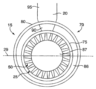
[0012] Figure 2 is a sectional side elevation taken in the direction of line 2-
2
of Figure 1.
[0013] Figure 3 is an enlarged view of the power plant of Figure 2 with
portions of the nacelle thereof sectioned and broken away to show details of
the
present invention.
[0014] Figure 4 is a rear elevation of the gas turbine engine power plant
shown in Figure 3.
DE'I'AILED DESCRIPTION OF THF.. INVENTION
[0015] Referring to Figures 1 and 2, a commercial gas turbine engine
powered aircraft includes a wing 10 liaving one or more gas turbine engine
power
plants 15 mounted on the underside thereof by a pylon 20. As best seen in
Figure
3, gas turbine engine power plant 15 comprises a gas turbine engine 25
characterized by a longitudinal central axis 27 which lies in a horiiontal
(under
norinal operating conditions) central plane 29 of the engine. In a matiner
well
known in the art, gas turbine engine 25 includes a case 35 enclosing a
coinpressor
40 (not shown), a combustor 45 (not shown), and a tttrbine 50 (alsc) not
shown),
the details of which are well known in the art. As is also well known in the
art,
air entering compressor. 40 through inlet 55 is compressed in the compressor,
and
enters the combustor where it is mixed with jet fuel and burned, the products
of
combustion (working fluid) flovving into turbine 50 which extracts energy
therefrom to drive the compressor and provide thrust for powerinK the
aircraft.
The turbine also drives a fan 60 comprising blades 65 of fixed or adjustable
pitch.
4
CA 02598304 2007-08-22
As blades 65 rotate, they take in ambient air, and accelerate the air to
provide the
majority of the useful thrust produced by the engine. Typically, due to the
much
larger diaincter of the fan compared to that of the core engine, in modern
tttrbofan engines, the volumetric flow through the fan can be as high as 5-10
times
the volumetric flow through the core engine or in some cases, even higher.
[0016] For purposes of maintaining a controlled flow of air, both around
the outside of the power plant and through the core engine, the engine and fan
are surrounded by a nacelle 70 comprising a core engine cowl 75 wluch
surrounds
the core engine and a fan cowl 80 disposed around the exterior of the core
cowl
and defining therewith, a generally annual fan duct 85 which accominodates the
flow of ambient air accelerated by fan 65, terminating at fan exhaust nozzle
86 at
the downstream end of the fan duct. A tail cone 87 may be provided at the
turbine exhaust nozzle to smooth the flow of working fluid exhausted from the
turbine.
[0017) In a manner well known in the art, the engine 25 and nacelle 70 are
fixed to the wing 10 of aircraft 5 by pylon 20. Pylon 20 is fixed to a wing
spar or
otlier suitable structural component of the aircraft (not shown) at one end
thereof,
and, at the other end thereof, to the engine and nacelle. The pylon comprises
a
structural beam 90 which provides support for the engine and nacelle,
transmitting the weight and operational (aerodynamic) loads thereof to the
wing
of the aircraft, and a faring 95 which provides a smooth aerodynamic contour
to
the pylon, reducing the aerodynamic iosses associated with fan airflow
therearound as the power plant moves through the air with the aircraft.
I00181 It will be readily apparent that a significant amount of fan airflow
through fan duct 85 will be blocked at an upper portion of the fan duct by
pylon
95. It has long been recognized that the blockage of fan air in the upper
portion of
the fan duct by the pylon contributes a significant amount of drag as the
engine
and pylon move through the ambient air. However, in accordance with the
present invention, it has been determined that the flow restriction imposed on
fan
airflow through the fan duct in prior art gas turbine engine power plants also
results in a higher volLUnetric flow rate of air through the lower (away from
the
pylon) portion of the fan duct than the upper portion thereof. That is, the
flow
blockage in the fan duct associated with the pylon, causes a net migration of
fan
airflow frotn the upper portion of thc fan duct, to the lower portioii
thereof. As
CA 02598304 2007-08-22
set forth hereinabove, for maximum efficiency, the thrust produced both by the
fan and the core engine should be directed parallel to the centerline of the
engine.
It has been determined that the greater flow through the lower portion of the
fan
duct skews the direction of the net thrust produced by the engine from an
axial
direction, thereby lowering the engine's efficiency so that the fuel
consumption of
the engine is increased from that which could be by a uniform fan airflow
around
the entire fan duct.
[0019] In accordance with the present invention, to compensate for the
flow restriction of the pylon in the upper portion of the fan duct, the cross
sectional flow area of the fan exhaust nozzle at an upper portion (toward the
pylon) thereof, i.e., that portion above the horizontal mid-plane of the
engine is
increased over the area of the fan exhaust nozzle below the engine (away from
the
pylon) mid-plane. This increase in the upper portion of the fan exhaust nozzle
reduces the tendency of the fan flow to niigrate toward the lower portion of
the
nozzle in response to the blockage associated with the pylon thereby
correcting
what otherwise would result in a vertical skewing of the net thrust produced
by
the engine.
100201 The area of the upper portion of the fan exhaust nozzle inay be
increased in several different ways. For example, the downstream portion of
the
fan cowl may be vertically offset upwardly (toward the pylon) from a position
concentric w.ith the core engine. That is, the downstream portion of the
longitudinal centerline of the fan cowl may be offset vertically upwardly
(toward
the pylon) from the centerline of the core engine at shown at 100 in Figure 3.
The
increased flow area at the upper portion of the fan exhaust nozzle may also be
achieved by offsetting core cowl 75 downwardly (away from the pylon) such that
the longitLidinal axis 110 thereof is offset downwardly from the longitudinal
centerline of the engine. Where a tail cone is used in the present invention,
the
extreme downstream-end of the core cowl should be made symmetric with the
core engine and tail cone so as not to ver.tically skew the direction of the
thrust
produced by the core engine.
[0021] The difference in cross-sectional areas between lhe two portions of
the fan exhaust nozzle and thus, the amount of vertical displacement of the
fan
cowl and core cowl to achieve the increased area in the upper portion of the
fan
duct will, of course, depend upon the engine's thrust rating and by-pass
ratio,
6
CA 02598304 2007-08-22
dimensions of the pylon and dimensions and operational parameters of the core
engine and fan. In general, the larger the engine, the larger the area of the
pylon
which partially blocks fan flow through the upper portion of the fan duct,
thereby
requiring a larger increase in fan duct area over that which would be required
with smaller engines. While in the preferred embodiment, the increased flow
area in the upper portion of the fan duct is achieved by offsetting the fan
duct
toward the pylon from the center line of the core engine and offsetting the
core
cowl away from the pylon with respect to the engine's centerline, it will be
appreciated that depending upon the relative configuration of the engine
nacelle
and pylon, it inay be possible to achieve the necessary increase in fan
exhaust
nozzle area by offsetting only one of these components from the centerline of
the
engine.
[0022] While the fan duct and core cowl have been shown to be generally
circular in cross section as is normally the case for equalization of
aerodynamic
loading therearound, it will be appreciated that for other considerations,
cross
sectional shapes of these components may vary from circular. It will also be
understood that although the pylon supports the engine from a location below
the
wing of the aircraft in the illustrative (preferred) embodiment, the present
invention may be employed with other configurations of power plants relative
to
the aircraft. For example, the invention herein may be used in aircraft in
which
the power plants are mounted above the aircraft's wings or on the sides of the
fuselage.
[0023] Accordingly, while the invention herein as been described in
reference to a specific preferred embodiment, it will be understood that those
variations thereof set forth herein as well as other variations and
modifications
may suggest theinselves to persons skilled in the art, and it is intended by
the
following claims to cover any such variations or modifications as fall within
the
true spirit and scope of this invention.
7