Note: Descriptions are shown in the official language in which they were submitted.
CA 02598597 2007-08-22
WO 2007/038818 PCT/AU2006/001269
- 1 -
GRAVITY GRADIOMETER
Field of the Invention
This invention relates to a gravity gradiometer, and in
particular, but not exclusively, to a gravity gradiometer
for airborne use. The invention has particular
application for measuring diagonal and off-diagonal
components of the gravitational gradient tensor.
Background of the Invention
Gravimeters are widely used in geological exploration to
measure the first derivatives of the earth's gravitational
field. Whilst some advances have been made in developing
gravimeters which can measure the first derivatives of the
earth's gravitational field because of the difficulty in
distinguishing spatial variations of the field from
temporal fluctuations of accelerations of a moving
vehicle, these measurements can usually be made to
sufficient precision for useful exploration only with
land-based stationary instruments.
Gravity gradiometers (as distinct from gravimeters) are
used to measure the second derivative of the gravitational
field and use a sensor which is required to measure the
differences between gravitational forces down to one part
in 1012 of normal gravity.
Typically such devices have been used to attempt to locate
deposits such as ore deposits including iron ore and
geological structures bearing hydrocarbons.
International publication WO 90/07131 partly owned by the
present applicants associated company discloses a gravity
gradiometer. The gradiometer includes a gimbal bearing
arrangement comprised of three concentric rings in which
is mounted the sensing equipment. The sensing equipment
generally comprises two spaced apart bars respectively
CA 02598597 2013-05-30
located in shielded housings and each mounted on a web
bearing. The instrUMent diaClosed 1.4 that application is
relatively complicated in that it includes a large number
Of part A and is relatively heavy which is a disadvantage
particularly in airborne applications.
S14pMary of the Invention
The invention provides a gravity gradiometer for measuring
Components of gravity gradient tensor comprising:
a sensor for measuring the components of the
gravity gradient tensor;
a mounting for mounting the sensor for movement
about three substantially orthogonal axes, and
actuators for moving the sensor on the mounting
15, about said axes;
wherein the sensor comprises a first mass and a
second mass supported within respective first and second
housings for movements relative to the housings in
response to the gravitational field characterized in that
at least one of the sensor masses also forms an
angular accelerometer for detecting angular movement of
=
the sensor And for producing a control signal for
application to at least one of the actuators so that the
at least one of the actuators applies a torque to the
25 sensor to stabilize the angular movement of the sensor on
the mounting.
The invention further provides a gravity gradiometer for
measuring components of gravity gradient tensor,
comprising:
3G a pair of: transversely arranged sensor masses for
measuring the components of the gravity gradient tent-Or;
a mounting for mounting the masses about three
substantially orthogonal axet;
actuators for moving the: mounting about the axes
35 to Stabilise the mounting and therefore the sensor masses;
and
CA 02598597 2013-05-30
- 2a -
angular accelerometer for detecting angular movement of
the masses and for producing a control signal for
application to at least one of the actuators so that the
at least one of the actuators applies a torque to the
mounting to stabilise the angular movement of the mounting
and therefore the sensor masses.
Preferably three actuators are provided, each for
providing a torque for moving the mounting about a
respective one of the axes to stabilise the mounting.
Preferably both the sensor masses form the angular
accelerometer, the sensor masses each having two sensor
coils for providing output signals indicative of the
115 components of the gravity gradient tensor and of angular
movement of the masses
=
Preferably the signal indicative of the components of the
gravity gradient tensor comprise a difference between
CA 02598597 2007-08-22
WO 2007/038818 PCT/AU2006/001269
- 3 -
signals produced by each coil of a respective sensor mass
and the signal indicative of the angular movement
comprises the sum of the signals from the coils of each
mass.
Preferably the coils are connected to a transformer and an
output winding of the transformer provides the signal
indicative of the angular movement of the masses.
Preferably the mounting comprises a first mount section, a
second mount section, a first flexure web for pivotally
coupling the first and second mount sections for pivotal
movement about a first axis, the second mount section
having a first part, a second part and a third part, the
first part connecting to the second part by a second
flexure web for pivotally coupling the first part to the
second part for pivotal movement about a second axis
orthogonal to the first axis, and the third part being
coupled to the second part by a third flexure web for
pivotally coupling the third part to the second part for
pivotal movement about a third axis orthogonal to the
first and second axes.
Preferably the first flexural web divides the first mount
into a primary mount portion and a secondary mount
portion, the sensor being connected to one of the primary
mount portion and secondary mount portion and the other of
the primary mount portion and second mount portion being
fixed, so that the primary mount portion can pivot
relative to the secondary mount portion about the first
flexural web to thereby pivotally couple the first and
second mount sections for pivotal movement about the first
axis.
In one embodiment of the invention the first mass
comprises a first bar and the second mass comprises a
second bar.
CA 02598597 2007-08-22
WO 2007/038818 PCT/AU2006/001269
- 4 -
In the preferred embodiment of the invention the first bar
is coupled to the first mount section and the second bar
is coupled to the first mount section.
Preferably the first bar and second bar are arranged
transverse with respect to one another. Most preferably
the first bar and second bar are arranged orthogonal to
one another.
Preferably the first bar is located in a first housing
which is fixed to the first mount section, the first bar
being connected to the first housing portion by a fourth
flexure web for movement relative to the first housing in
response to the gravitational field.
Preferably the second bar is located in a second housing
fixed to the first mount section and connected to the
second housing by a fifth flexure web so the second bar
can move relative to the second housing in response to the
gravitational field.
Brief Description of the Drawings
Preferred embodiments of the invention would be described,
by way of example, with reference to the accompanying
drawings, in which:
Figure 1 is a schematic view of a gradiometer of
one embodiment of the invention.
Figure 2 is a perspective view of a first mount
forming part of a mounting of the gradiometer of the
preferred embodiment;
Figure 3 is a view of a second mount of the
mounting;
Figure 4 is a view from underneath the mount of
Figure 3;
Figure 5 is a cross-sectional view along the line
IV-IV of Figure 3;
CA 02598597 2007-08-22
WO 2007/038818 PCT/AU2006/001269
- 5 -
Figure 6 is a cross-sectional view along the line
V'-'V of Figure 3;
Figure 7 is a view of the assembled structure;
Figure 8 is a view showing the sensor mounted on
the gimbal structure;
Figure 9 is a plan view of a bar of the preferred
embodiment;
Figure 10 is a diagram showing actuator control;
Figure 11 is a block diagram showing operation of
the rotatable support system;
Figure 12 is a view of a gradiometer of the
preferred embodiment;
Figure 13 is a view of a first mount of a second
embodiment;
Figure 14 is a view of part of the mounting of
Figure 13 to illustrate the location and extent of the
flexural web of the first mount;
Figure 15 is a view of the mounting of Figure 13
from beneath;
Figure 16 is a view of the mounting of Figure 13
including a second mount of the second embodiment;
Figure 17 is a cross-sectional view through the
assembly shown in Figure 16;
Figure 18 is a view from beneath of the section
shown in Figure 17;
Figure 19 is a view from beneath of the second
mount of the second embodiment;
Figure 20 is a view of the second mount of Figure
19 from above;
Figure 21 is an exploded view of the second mount
of the second embodiment;
Figure 22 is view of the assembled mounting and
sensors according to the second embodiment;
Figure 23 is a perspective view of the
gradiometer with some of the outer vacuum container
removed;
Figure 24 is a plan view of a housing for
CA 02598597 2007-08-22
WO 2007/038818 PCT/AU2006/001269
- 6 -
supporting a bar according to a further embodiment of the
invention;
Figure 25 is a more detailed view of part of the
housing of Figure 24;
Figure 26 is a view of a transducer used in the
preferred embodiment;
Figure 27 is a view similar to Figure 25 but
showing the transducer of Figure 26 in place;
Figure 28 is a diagram to assist explanation of
the circuits of Figures 29 and 30;
Figure 29 is a circuit diagram relating to the
preferred embodiment of the invention, particularly
showing use of one of the sensors as an angular
accelerometer;
Figure 30 is a frequency tuning circuit;
Figure 31 is a cross-sectional view through an
actuator according to one embodiment of the invention;
Figure 32 is a view of part of the actuator of
Figure 31;
Figure 33 is a diagram illustrating balancing of
the sensors of the gradiometer of the preferred
embodiment; and
Figure 34 is a circuit diagram of a calibration
sensor used when balancing the gradiometer.
Detailed Description of the Preferred Embodiments
Figure 1 is a schematic view of a gravity gradiometer
according to the preferred embodiment of the invention.
The gradiometer shown in Figure 1 comprises a double
walled Dewar 1 which is supported in an external platform
2. The external platform 2 enables adjustment of the
Dewar and therefore the contents of the Dewar about three
orthogonal axes. The external platform 2 is generally
known and its adjustment by suitable motors or the like is
also known. Thus, a detailed description will not be
provided.
_
CA 02598597 2007-08-22
WO 2007/038818 PCT/AU2006/001269
- 7 -
A vacuum canister 3 is provided in the Dewar and the Dewar
is supplied with liquid gas such as liquid helium He so
that the gradiometer can operate at cryogenic temperature.
The Dewar 1 is closed by an end plate 4 which includes
connectors 5a for connecting electrical leads (not shown)
to external components (not shown).
The canister 3 is closed by an end plate 9 which includes
connectors 5b for connecting electric leads (not shown) to
the connectors 5a. The gradiometer has a main casing 61
formed from a twelve-sided ring 62 and hemispherical domes
63 (see Figure 12). An internal mounting 5 is connected
to the ring 62. The ring 62 carries a support 65 to which
a feed through flange 9 is coupled. A neck plug 11 formed
of baffles lla which sandwich foam llb is provided above
the canister 3. The baffles ha are supported on a hollow
rod 93 which extends to the canister 3 and which is also
used to evacuate the canister 3.
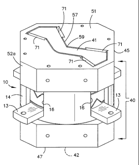
With reference to Figure 2 a first mount 10 of a rotatable
mounting 5 (Figure 7) of the gradiometer is shown which
comprises a base 12 and an upstanding peripheral wall 14.
The peripheral wall 14 has a plurality of cut-outs 16.
The base 12 supports a hub 18.
Figures 3 and 4 show a second mount 20 which comprises a
peripheral wall 22 and a top wall 24. The peripheral wall
22 has four lugs 13 for connecting the mount to the casing
61. The top wall 24 and the peripheral wall 22 define an
opening 28. The peripheral wall 22 has a first part 25, a
second part 26 and a third part 27. The second mount 20
is a monolithic integral structure and the first part 25
is formed by making a circumferential cut 19 through the
peripheral wall except for the formation of flexure webs
as will be described hereinafter. The third part 27 is
formed by making a second circumferential cut 29 through
CA 02598597 2013-02-12
...............................................................................
..................
= WO (2007/0:38:6-$$
MiØ21)96i0040
= =
the
22 except for flexure Vtehe 1.444.11.: wiU
4.1=sa=::=be======deicr4.44 =hereixt4fter.. eiedeutl lucurit 20
14 =
itteUUtect.==Cii.== the...first mewt1,0: ht. lOCetlitl. the hib 1EIntob
p47.*; upeni 2 and the lug10,thcih............ *14:tot.40.
= = = =
= . tfi ;::44i -40.114)*
The t,O.=õ
=074,= Ipti=toO14 161:44ht =
..a0a t ;1,000.09 11.4b: 31 6t#ed.: ;lc the f*ret:
uitkitit Q tO
pr4tery x*etatprtn f the rimukit 141 t*a..pivot About to-
r44:e4t.t4...vo) to ==a acØ4<iery #1.ctult ptirtitirt o the ......
Th 1..a
11 'he Aast;iti:h444 irtete ;ti.e,.te,*1.,, with ret:f it0000
the sec onci- P;40444.4.4t 413-4:,ia& 3 to 21,
:The
lugs i3cOut*Nect the w;r1.1.01:414. S JL WA, :ottitittif%r 3
.741.3411,.. in tarn., 4...00tep Dewor *if....OF ryoene
=operatiou *0 UWW0g04,44.4istOP.
The Pi1:04;.` ...................... tg.;;00.$**tecit
:ert4irltaa 53.2*.trorp.
= ror or,mrg rptAt0..oro*eontroI qf the: ItrAcliopliter 41.1ioxt
=:µ
20. µttt.me.e. prthOrm.441., *4 ye #==aaThp.B motuiting
the =
Aeriecor 40 :.(whiph, will be *soo ....... -11:i:theta detail .
:,.:.= = ========
.ber.:014..,nArtor Ø24 wh cth aa.. prefe#4h,1y *A-
d.14V.P916.) =fOr=-:much = e 441ov .tottiti6ruo.,,a itmet
out the
.== . .
x, y
end 4: 4xes =for
the 4r,40..C*.eter.::'.:41#4,44H7.40
:2S
ttltl.ng :or; 1.6.044'ort.tamiAtso POW:t4q.0"-kW,....4( 4.9r1 ths
W.F.4tnc4:03740=1:1=0
eitbogue.
=
The
t: :e: Web 31 4./.1m4iii 04 0070 #400# tffi littOre:
=
=
the 0.440040. Actuat 20 *bomb
==
'igire
.;
=FS edOkit Vit*St: .404 tt* ttlt ::044
:.=
repeotiirel1r
W1/4.44::X tur4 re a1e the oirtp 14. Ø(
'shown, i igire 3.
he perip.lao:Oal wa34 22may 1.:xe: cut. Si!
45 city siit1eouttittg. =trietrursect Arch. ea 4 .144.re cutter or
:rigure :5 atOVs; the:ottont u..ace'1=41 forp420.4.. 10y.
the 9114
46, 44 *parent, -from Fig:urea 3 anti:. S the cce* =
::::
=
CA 02598597 2013-02-12
. .
WO:2007/01MS
P4.7.T4M44461.M.M
... 0
.19 has two inti'arted v-phaped peaks 34. The ape-a the
peaks 34 is not out: and therefore form a second fle*ure:
web 33 which join, the first part 23 to the pepo04.patt 26.
T4,40, the second part 26 is aW.e to pivotal4 rotatm
gel.eti.ve to the first part 25 about the
,.... The second 00 29 is: shown in Figure. 6 and ;left the
bottom Surface 294 fOrMed by. the out 29 is ',Visible. Again
= the second out 29: fOrMs two v=P'Shaped peaks 36. and the
epelges of the peaks 36 .are not cut and therefOra form a
third flexure limb 37 which connect the second part 0: to
the third part 27. Thus, the third part 27: is able to
pivotal, rotate about. the y axis.
=
=
Wigure shows sensor 40 mounted on the mounting. he
=
sensor 40 is an Orthogonal Quadrupole Responder OR
sensor formed of a first mass and a second mass ,in the
=
4oro: of a first bar 41 and. a second bar 42 (not 00.14% in
ngure orthogonal to the bar 41 and Which 40 of the
same shape as the bar 41.
24
The bar. 41 is formed in a first: housing 46 and the bar 42
4a formed in a second housing 47. The .44v, 0 and ho25$14
45 la the 0044e as bar:42 and the 49.**44g 47 eXekiit that
one 44; rotated 90! with respect to the other pp that the
tt bare are orthovnal, gepce only the houaing 45 wiLl 11;;:a
dasor4b04.
the helleing: 46 heo an. AA4 11404 51 end a perilihpral aide
wall :52a, The end W441 1iS 0entecto4 to: .4x0:6
eud 4) of thoval AA of the g..',.#4s11.:Iq9,4 10 OY *91**1
the likei (not shown) . The bar 41 is feed by a ellt 57 in
the. well 51 :except for a fourth glexuke web 9 *b..4.4h aptpip
the .bat 41 to: the wall 61. The flexure -Ob. 012.0*
enletged in the top vietellif: the bar 41 in FigUre.
After
3.3 the bar 41 is 010 tO:Pivotteletive t0 th6 h011eingAS in
reSOCkite to: chan----in the owatationa field. The bax
=
= 42, in: Pidlinted in the woo wey as. mentioned aheVe: and al00
=
CA 02598597 2007-08-22
WO 2007/038818 PCT/AU2006/001269
- 10 -
can pivot relative to its housing 47 in response to
changes in the gravitational field about a fifth flexure
web 59. The housing 47 is connected to base 12 (Figure 2)
of the first mount 10.
The bar 41 and the housing 45 together with the flexure
web 59 are an integral monolithic structure.
Transducers 71 (not shown in Figures 2 to 6) are provided
for measuring the movement of the bars and for producing
output signals indicative of the amount of movement and
therefore of the measurement of the differences in the
gravitational field sensed by the bars.
Figure 10 is a schematic block diagram showing actuator
control to stabilise the gradiometer by rotating the
mounting 5 about three orthogonal axes (x, y, z). A
controller 50 which may be a computer, microprocessor or
the like outputs signals to actuators 52, 53, 54 and 55.
The actuator 52 could rotate the mounting 5 about the x
axis, the actuator 54 could rotate the mounting 5 about
the y axis and the actuator 54 could rotate the mounting 5
about the z axis. However, in the preferred embodiment,
two of the four actuators 52, 53, 54 and 55 are used to
rotate the mounting about each axis so that rotation about
each axis is caused by a combination of two linear
movements provided from two actuators. The linear
movement provided by each actuator will be described with
reference to Figures 31 and 32. The position of the
mounting 5 is monitored so that appropriate feedback can
be provided to the controller 50 and the appropriate
control signals provided to the actuators to rotate the
support 10 as is required to stabilise the support during
movement through the air either within or towed behind an
aircraft.
The preferred embodiment also includes angular
CA 02598597 2007-08-22
WO 2007/038818
PCT/AU2006/001269
- 11 -
accelerometers which are similar in shape to the bars 41
and 42 but the shape is adjusted for zero quadrupole
moment. The linear accelerometers are simple pendulous
devices with a single micro pivot acting as the flexural
hinge.
Figure 11 is a view of a feedback control used in the
preferred embodiment.
Figure 12 is a cut away view of the gradiometer ready for
mounting in the Dewar 1 for cryogenic operation which in
turn is to be mounted in the external platform. Although
Figures 2 to 8 show the gradiometer with the bars 41 and
42 top and bottom, the instrument is actually turned on
its side (900) so that the bars 41 and 42 are at the ends
as is shown in Figure 12.
Figure 12 shows the mounting 5 arranged within the casing
61 and formed by the ring 62 and the transparent
hemispherical ends 63. The ring 22 has connectors 69 for
connecting the internal wiring from transducers 71 (see
Figure 8) and SQuID (Superconducting Quantum Interference
Device) Electronics located in the casing 61 to the
connectors 5b (Figure 1).
The transducers 71 measure the angle of displacement of
the bars 41 and 42 and the control circuitry (not shown)
is configured to measure the difference between them.
Error correction can be performed numerically based on
digitised signals from the accelerometers and a
temperature sensor.
The transducers 71 are SQuID based transducers and the
error correction is made possibly by the large dynamic
range and linearity of the SQuID based transducers.
CA 02598597 2007-08-22
WO 2007/038818 PCT/AU2006/001269
- 12 -
Figures 13 to 21 show a second embodiment in which like
parts indicate like components to those previously
described.
In this embodiment the first mount 10 has cut-outs 80
which effectively form slots for receiving lugs (not
shown) which are connected to the mount 10 in the cut-outs
80 and also to the second mount 20 shown in Figures 19 to
21. In this embodiment the lugs are separate components
so that they can be made smaller, and more easily, made
than being cut with the second mount section 20 which
forms the second flexure web 33 and the third flexure web
37.
In Figure 13 a cut 87 is made to define the part 18a of
the hub 18. The cut 87 then extends radially inwardly at
88 and then around central section 18c as shown by cut
101. The cut 101 then enters into the central section 18c
along cut lines 18d and 18e to define a core 18f. The
core 18f is connected to the central section 18c by the
flexural web 31 which is an uncut part between the cut
lines 18e and 18d. The part 10a therefore forms a primary
mount portion of the mount 10 which is separated from a
secondary mount portion 10a of the mount 10 except for
where the portion 18a joins the portion 10a by the
flexural web 31. The part 18a effectively forms an axle
to allow for rotation of the part 18a relative to the part
10a in the z direction about the flexure web 31.
As is shown in Figure 14, the cut line 88 tapers outwardly
from the upper end shown in Figure 14 to the lower end and
the core 18c tapers outwardly in corresponding shape, as
best shown in Figure 17.
As is apparent from Figures 13 to 18, the first mount 10
is octagonal in shape rather than round, as in the
previous embodiment.
CA 02598597 2007-08-22
WO 2007/038818 PCT/AU2006/001269
- 13 -
=
Figures 19 to 21 show the second mount 20. Figure 16
shows the second mount 20 mounted in the first mount 10.
As is best shown in Figures 19 and 20, the second mount 20
has cut-outs 120 which register with the cut-outs 80 for
receiving lugs (not shown). The lugs can bolt to the
second mount 20 by bolts which pass through the lugs and
into bolt holes 121. The lugs (not shown) are mounted to
the mount 20 before the mount 20 is secured to the first
mount 10.
In the embodiment of Figures 19 and 20, the peaks 34 and
inverted peaks 35 are flattened rather than of V-shape as
in the previous embodiment.
In this embodiment, top wall 24 is provided with a central
hole 137 and two attachment holes 138a. Three smaller
holes 139a are provided to facilitate pushing of the
housing 45 off the part 18a if disassembly is required.
When the second mount 20 is located within the first mount
10, the upper part of central section 18c projects through
the hole 137, as best shown in Figure 16. The mount 20
can then be connected to the mount 10 by fasteners which
pass through the holes 138 and engage in holes 139b (see
Figure 13) in the part 18a.
Thus, when the first housing 45 and its associated bar 41
is connected to the rim 75 of the housing 10 and the
second housing 47 is connected to the base 12, the
housings 45 and 47 and their associated bars 41 and 42 are
therefore able to move about three orthogonal axes defined
by the flexure web 31, the flexure web 33 and the flexure
web 37.
As is best seen in Figure 21 which is an exploded view of
the three parts 25, 26 and 27 which make up the second
mount 20, an opening extends through the mount 20 which is
CA 02598597 2007-08-22
WO 2007/038818 PCT/AU2006/001269
- 14 -
formed by the hole 137, hole 138 and hole 139. It should
be understood that the mount 20 shown in Figure 21 is a
monolithic structure and is merely shown in exploded view
to clearly illustrate the location of the flexural webs 33
and 35. Obviously the flexural web 33 shown in Figure 21
joins with the part 26 and the flexural web 35 shown in
Figure 21 joins with the part 27. The holes 137, 138 and
139 define a passage through which the axle or first
portion 18a of the first mount 10 can extend when the
second mount 20 is located in the first mount 10.
Thus, when the second mount 20 is fixed to the part 18a,
the second mount 20 can pivot with the first portion 10a
of the first mount 10 about a z axis defined by the
flexure web 31 whilst the second portion formed by the
part 18a remains stationary. Movement about the x and y
axes is achieved by pivotal movement of the second mount
about the flexure webs 33 and 35 as previously
described.
Figure 22 shows the linear and annular accelerometers 90
fixed to the housings 45 and 47.
The gravity gradient exerts a torque on a rigid body with
any mass distribution provided it has a non-zero
quadrupole moment. For a planar body, in the x-y plane
and pivoted about the z-axis, the quadrupole is the
difference between moments of inertia in the x and y
directions. Thus a square or circle has zero quadrupole
moment, while a rectangle has a non-zero value.
The torque produced is what constitutes the signal
measured by the gradiometer.
There are two dynamical disturbances which can also
produce torques and consequently are sources of error.
CA 02598597 2007-08-22
WO 2007/038818 PCT/AU2006/001269
- 15 -
The first is linear acceleration.
This produces a torque if the centre of mass is not
exactly at the centre of rotation - i.e. the bar is
"unbalanced". The bars 41 and 42 are balanced as well as
possible (using grub screws to adjust the position of the
centre of mass) but this is not quite good enough, so
there is a residual error. This error can be corrected by
measuring the linear acceleration and using this to
numerically subtract away the erroneous part of the
signal.
The second is angular motion.
There are two aspects to angular motion, each of which
produces a different error.
The first is aspect angular acceleration.
Angular acceleration produces a torque on the mass
distribution through its moment of inertia (even if the
quadrupole moment is zero). This is an enormous error and
two preferred techniques are used to counteract it.
The first is to use internal rotational stabilization.
This is depicted in the block diagram of Figure 10. Here
Ho(s) represents the sensor assembly pivoted about the
mounting 5 (as per Figure 9). The block A(s) represents
the actuator, which provides the feedback torque to effect
the stabilization by canceling the applied disturbances.
T(s) represents the sensor (or transducer) which measures
the effect of the applied disturbance. This is the
angular accelerometer. Using angular accelerometers in
rotational control is unusual - usually gyros and/or
highly damped tilt meters are used, but for our purpose
the angular accelerometers are better, as the error is
proportional to the angular acceleration disturbance.
CA 02598597 2007-08-22
WO 2007/038818 PCT/AU2006/001269
- 16 -
The second is to use common mode rejection CMRR - that is
why 2 orthogonal bars are needed. For the two bars, the
error torque produced by the angular acceleration is in
the same direction, but the signal torque produced by the
gravity gradient is in opposite direction.
Therefore, by measuring the difference in deflection
between the two bars, the gradient is sensed but not the
angular acceleration.
Therefore, two separate angular accelerometers 90 (labeled
90' in Figure 22 for ease of identification) are provided.
We have two independent output signals from the pair of
OQR bars 41 and 42. The first is proportional to the
difference in deflection, which gives the gradient signal
and the second is proportional to the sum of their
deflections, which is proportional to the angular
acceleration and provides the sensor for the z-axis
rotational control.
The x and y axes require separate angular accelerometers.
Rotational stabilization about these axes is required
because the pivot axes of the two bars are not exactly
parallel and also to counteract the second form of error
produced by angular disturbance, discussed below.
The second aspect is angular velocity.
Angular velocity produces centrifugal forces, which are
also a source of error. The internal rotational
stabilization provided by the actuators reduces the
angular motion so that the error is below 1 Eotvos.
Figure 23 shows main body 61 and connector 69 with the
hemispherical ends removed.
CA 02598597 2007-08-22
WO 2007/038818 PCT/AU2006/001269
- 17 -
Figure 24 is a plan view of housing 45 according to a
still further embodiment of the invention. As is apparent
from Figure 24, the housing 45 is circular rather than
octagonal, as is the case with the embodiment of Figure 8.
The housing 45 supports bar 41 in the same manner as
described via flexure web 59 which is located at the
centre of mass of the bar 41. The bar 41 is of chevron
shape, although the chevron shape is slightly different to
that in the earlier embodiments and has a more rounded
edge 41e opposite flexure web 59 and a trough-shaped wall
section 41f, 41g and 41h adjacent the flexure web 59. The
ends of the bar 41 have screw-threaded bores 300 which
receive screw-threaded members 301 which may be in the
form of plugs such as grub screws or the like. The bores
300 register with holes 302 in the peripheral wall 52a of
the housing 45. The holes 302 enable access to the plugs
301 by a screwdriver or other tool so that the plugs 301
can be screwed into and out of the bore 300 to adjust
their position in the bore to balance the mass 41 so the
centre of gravity is at the flexure web 59.
As drawn in Figure 24, the bores 300 are a 450 angle to the
horizontal and vertical in Figure 24. Thus, the two bores
302 shown in Figure 24 are at right angles with respect to
one another.
Figure 24 also shows openings 305 for receiving the
transducer 71 for monitoring the movement of the bar 41
and producing signals which are conveyed to the SQUID
device. Typically, the transducer is in the form of a
coil and as the bar 41 moves slightly due to the gravity
difference at ends of the bar, a change in capacitance
occurs which alters the current in the coil to thereby
provide a signal indicative of movement of the bar 41.
Figure 25 is a more detailed view of part of the housing
CA 02598597 2007-08-22
WO 2007/038818 PCT/AU2006/001269
- 18 -
of Figure 24 showing the openings 305. As can be seen
from Figure 25, the openings 305 have shoulders 401 which
form grooves 402. A spring 403 is arranged adjacent
surface 406.
Figure 26 shows the transducer 71. The transducer 71 is
formed by a generally square macor plate 410 which has a
circular boss 407. A coil 408 is wound about the boss 407
and may be held in place by resin or the like. The coil
408 may be multi-layer or a single layer coil.
Figure 27 shows the location of the plate 410 in the
opening 305 in which the plate locates in the grooves 402
and is biased by the spring 403 against the shoulders 401
to hold the plate 410 in place with the coils 408 being
adjacent the edge face 41a of the bar 41.
Thus, the coil 408 and the bar 41 form an lc circuit so
that when the bar 41 moves, the current passing through
the coil 408 is changed.
As will be apparent from Figure 24, four transducers 71
are arranged adjacent the ends of the bar 41. The other
housing 47 also has four transducers arranged adjacent the
bar 42. Thus, eight transducers 71 are provided in the
gradiometer.
Figure 28 is a diagram of the bars 41 and 42 showing them
in their "in use" configuration. The transducers which
are located in the openings 305 are shown by reference
numbers 71a to 71e to equate to the circuit diagrams of
Figures 29 and 30.
With reference to Figures 29 and 30, transducers 71a and
71b associated with the bar 41, and transducers 71g and
71e associated with the bar 42 are used to provide the
gravity gradient measurements.
CA 02598597 2007-08-22
WO 2007/038818 PCT/AU2006/001269
- 19 -
Input terminals 361 provide input current to the
superconducting circuits shown in Figure 29. Heat
switches which may be in the form of resistors 362 are
provided which are used to initially set the
superconducting current within the circuit. The heat
switches 362 are initially turned on for a very short
period of time to heat those parts of the circuit at which
the resistors 362 are located to stop those parts of the
circuit from superconducting. Currents can then be
imposed on the superconducting circuit and when the heat
switches formed by the resistors 362 are switched off, the
relevant parts of the circuit again become superconducting
so that the current can circulate through the circuits
subject to any change caused by movement of the bars 41
and 42 under the influence of the gravity gradient and
angular acceleration, as will be described hereinafter.
The transducers 71a, 71b, 71g and 71e are connected in
parallel to circuit line 365 and to circuit line 366 which
connect to a SQUID 367.
Thus, as the bars 41 and 42 rotate about their respective
flexure web, the bars 41 and 42, for example, come closer
to the transducer 71a and therefore further away from the
transducer 71b, and closer to the transducer 71h and
further away from the transducer 71g respectively. This
therefore changes the current flowing through the
transducers and those currents are effectively subtracted
to provide signals for providing a measure of the gravity
gradient.
As is shown in Figure 31, transducers 71c and 71d form a
separate circuit and are used for frequency tuning of the
bar 41 and transducers 71a and 71b. Similarly, the
transducers 71e and 71f are used for frequency tuning of
the bar 42 and the transducers 71g and 71h. Frequency
CA 02598597 2007-08-22
WO 2007/038818 PCT/AU2006/001269
- 20 -
tuning of the bars is important because the bars should be
identical in order to reject angular accelerations. The
frequency tuning circuits therefore enable electronic
tuning of the bars to match resonant frequencies and to
achieve mode rejection so that each of the bars does
function in an identical manner.
The transducers 71a, 71b, 71g and 71h are also used to
form angular accelerometers for measuring the angular
movement of the mounting 5 so that feedback signals can be
provided to compensate for that angular movement.
To do this, the line 366 is connected to a transformer
370. The polarity of the signals from the transducers 71a
and 71b and 71g and 71h are reversed so that the output of
the transducer 370 on lines 371 and 372 is an addition of
the signals rather than a substraction, as is the case
when the gradient is measured so the addition of the
signals gives a measure of the angular movement of the
bars. The outputs 371 and 372 are connected to SQUID
device 375 for providing a measure of the angular
acceleration which can be used in the circuit of Figure 10
to provide compensation signals to stabilise the mounting
5.
Thus, according to the preferred embodiment of the
invention, the angular accelerometers 90' provide a
measurement of angular acceleration, for example, around
the x and y axes, and the angular accelerometer formed by
the bars 41 and 42 and the transducers 71a, 71b, 71g and
= 71h provide a measure of the angular accelerometer around
the, for example, z axis.
Figures 31 and 32 show an actuator for receiving the
control signals to adjust the mounting in response to
angular movement of the mounting 5.
CA 02598597 2007-08-22
WO 2007/038818 PCT/AU2006/001269
- 21 -
The actuator shown in Figures 31 and 32 are schematically
shown in Figure 10 by reference numerals 52, 53, 54 and
55. All of the actuators are the same and Figures 31 and
32 will be described with reference to the actuator 52
which makes adjustment around the x axis shown in Figure
10.
Actuator 52 shown in Figure 31 has a hollow disc housing
310 which has a mounting bracket 311 for connecting the
disc housing 310 to mounting 5. The hollow disc housing
310 therefore defines an inner chamber 312 in which is
located coil support plate in the form of a disc 313. The
disc 313 has a wide hub section 314 and two annular
surfaces 315 and 316 onto which windings Wi and W2 of
coils are wound about the hub 314.
The disc 313 is also provided with a radial bore 319 and a
hole 320 at the periphery of the disc 313 which
communicates with the bore 319. A hole 321 is provided at
the hub 314 and communicates with the bore 319 and extends
to a hollow rod 328 which locates in a tube 330. The rod
330 is fixed to the disc 313 and also to support frame 340
which is fixed to main body 61 (not shown in Figure 31).
The tube 330 is connected to the disc housing 310 for
movement with the disc housing 310 relative to disc 313,
rod 328 and frame 340.
The winding Wi provided on the face 315 has a lead 331
which passes through the hole 320 and then through the
bore 319 to the hole 321 and then through the tube 328 to
the right, as shown in Figure 31. A lead 332 from the
other end of the winding Wi passes through the hole 321
and through the hollow rod 328 also to the right so that
current can be supplied to the winding W1 through the
leads 331 and 332.
The second winding W2 provided on the face 316 has a lead
CA 02598597 2007-08-22
WO 2007/038818 PCT/AU2006/001269
- 22 -
333 which passes through a radial hole 334 and bore 345 in
the disc 313 and then through hole 337 to tube 328 and to
the left in Figure 31. The other end of the winding W2
has a lead 338 which passes through the hole 337 into the
tube 328 and to the left in Figure 31. Thus, current can
circulate through the winding W2 via the leads 333 and
338.
When the windings W1 and W2 are energised or the current
passing through the windings changes, the disc housing 310
is moved relative to the disc 313 and frame 340 and
because the disc housing 310 is connected to the mounting
5 by the bracket 311, the mounting 5, in the case of the
actuator 52, is adjusted. The movement of the disc
housing 310 is generally a longitudinal movement (i.e.
linear movement) in the direction of the axis of the tube
330 and rod 328. To facilitate such movement, clearance
is provided between the ends of the rod 330 and the frame
340 and about the disc 313. The bracket 311 is offset
relative to the flexure web (such as the flexure web 37)
so that movement of the housing 310 applies a torque to
the first part 25 of the mounting 5 to cause rotation of
the part 25 about the flexure web 37.
In the preferred embodiment of the invention, four
actuators are provided for providing actual adjustment
about the various axes and flexure webs and the actuators
operate in combination in response to signals received
from the angular accelerometers to maintain stability of
the mounting 5 when the gradiometer is in use.
For cryogenic operation of the gradiometer, the mounting
5, housings 45 and 47, bars 41 and 42, the hollow disc
housing 310, coils, and electrical leads referred to
previously, are all made from superconducting material
such as niobium.
CA 02598597 2007-08-22
WO 2007/038818 PCT/AU2006/001269
- 23 -
In embodiments of the invention where the gradiometer is
not cryogenically operated, the components can be formed
from other materials such as aluminium.
The angular accelerometers 90' have zero quadrupole moment
which means that the centre of mass coincides with the
flexure web and that consequentially they are insensitive
to both gravity gradient and centrifugal force. Linear
accelerometers 90" (Figure 22) could also be provided.
The linear accelerometers 90" do not apply active
compensation but may apply corrections to the final
measured gradient data. Thus, data relating to linear
acceleration can be recorded and possibly used in later
processing.
One or both of the bars 41 and 42 can also be used as an
angular accelerometer to provide a measure of angular
movement of the mounting 5 so that appropriate feedback
signals can be generated to compensation for that movement
by control of the actuators previously described.
In the preferred embodiment, four angular accelerometers
are provided with two of the accelerometers being formed
by the bars 41 and 42. The use of four accelerometers
arranged at 45 angles with respect to one another enables
adjustment about the x, y and z axes by torque supplied
from two or more of the actuators at any one time.
The disc 310 prevents flux from the windings Wi and W2
from leaving the actuator and because the leads 331 and
332 and 333 and 338 leave the actuator through the
elongate tube 330, the ability of flux to pass out of the
actuator is substantially prevented.
Thus, spurious magnetic fields which may detrimentally
effect operation of the instrument are not generated by
the actuator and therefore do not influence the
CA 02598597 2007-08-22
WO 2007/038818 PCT/AU2006/001269
- 24 -
sensitivity or operation of the instrument.
The tube 330 preferably has a length to diameter ratio of
10:1 at the least.
The disc plate 316 is preferably formed from macor and the
hollow disc housing 310 is formed in two parts 310a and
310b. The part 310b forming a closure panel which enables
the disc 313 to be located in the chamber 312 and then the
disc housing 310 closed by locating the plate 310b in
place.
With reference to Figures 33 and 34, the manner in which
the balance of the bars 41 and 42 is achieved will be
described. A pair of displacement sensors formed by
capacitors 400 and 401 are provided for two main purposes:
1. To measure the residual linear acceleration
sensitivity of each bar 41 (and 42) to enable the
bars to be mechanically balanced using the grub
screws 301 described with reference to Figure 24,
before operation at low temperatures; and
2. To measure the induced linear acceleration
sensitivity of each bar 41 and 42.
The bars 41 and 42, in their respective housings, are
rotated in a jig (not shown) through 360 . This provides
an acceleration range of 2 gE, which is typically 100 times
greater than the accelerations which may be conveniently
applied at low temperature. A typically requirement is
for the capacitors 400 and 401 to be able to detect 0.1 nm
over a period of 1 to 20 minutes. A pair of capacitors
400 and 401 is required for each bar to provide some
discrimination against sensor drift, since rotation of the
bar 41 will cause one capacitor 400 to increase and the
other capacitor 401 to decrease by the same amount, as is
shown in Figure 33, whereas thermal expansion will cause
CA 02598597 2007-08-22
WO 2007/038818 PCT/AU2006/001269
- 25 -
both outputs of the capacitors 400 and 401 to increase.
The capacitors 400 and 401 remain in place, even though
they are unusable at low temperatures, and therefore their
components need to be non-magnetic so as to not interfere
with the operation of the gradiometer and, in particular,
its nearby superconducting circuitry.
Figure 33 shows that as the bar 41 pivots, the gap
applicable to the capacitor 400 decreases and the gap of
the capacitor 401 increases.
The capacitors 400 and 401 are formed by the face 41a of
the bar 41 (and the corresponding face on the other bar
42) and second plates 405 which are spaced from the face
41a. The gap between the plates of the respective
capacitors 400 and 401 must typically be resolved to about
1 ppm.
Figure 34 shows the calibration circuit applicable to the
capacitor 400. A circuit for the other capacitor 401 is
identical.
The capacitor 400 forms a high Q-factor resonant circuit
with inductor 410. The inductor 410 and capacitor 400 are
provided parallel to capacitors 411 and 412 and connect
via capacitor 413 to an amplifier 414. The output of the
amplifier 414 is provided to a frequency counter 415 and
also fed back between the capacitors 412 and 411 by line
416. The capacitor 400 therefore determines the operating
frequency of the amplifier 414 which can be read to a high
precision.
If the bar 41 is out of balance, the frequency counter 45
will tend to drift because of the imbalance of the bar.
This can be adjusted by moving the grub screws 301 into
and out of the masses as previously described until
balance takes place. The amplifier 414 can then be
CA 02598597 2013-02-12
= = --=::-===== ' '''' =
-;; ... .. ==== ..... =¨ == = === =
= =
WOI;Ø07:408.it
0340:**0001710
disecaawotoi*mn the ti*4444W: now** 45 so that fak
imealt.ctnetem: can bc arrOted-4Sithim tfie 10.0war I 40411 the
ettee.:Itiegte :41.444m.44; 4.4t2114. a4
044,
.. ""
=
=
i.KrB
=
=
A
Th. the :b1A14'd *MOW Zi1=161# 444 *1...),':*ct PV0P:044g,
41eettip1-,io-0.4: oftbe i4VehtLdAT except litheito the context
0401A001 othi414po,oxvitto =mean imeg*ece OrAWNWAI.OPY
#1,0440#6n,
the *eled ,Itotptte6! or vet.$04Hozgw SVOh 04
IS 0oijit*kbeke o 00bObtibibir Ixtba i. an inclubLye,
Ammer
4,44 to 44;6411,-th.4 :046S#00
th0.4t4t00 g04104P0.0'gt
. . . . . . . . . . . ,
t to pr 1xcLo the ::p.,vetergke o addition .of further:
features *0,veriibee embodiments of the tbrOAU0A.
o.
.;
=,: