Note: Descriptions are shown in the official language in which they were submitted.
CA 02598659 2015-07-30
CA 2598659
SHOULDER IMPLANT FOR GLENOID
REPLACEMENT AND METHODS OF USE THEREOF
Field of the Invention
The present invention relates to the field of total shoulder replacement.
Background
This disclosure provides a glenoid shoulder implant, a humeral implant, and
devices for
preparing the glenoid and humeral head for joint replacement.
Shoulder replacement surgery is currently used to treat patients suffering
from disabling
pain due to worn or damaged shoulder joints, which can be caused by, e.g.,
arthritis or injury.
The humeral implants currently in use are typically made from metal, and the
implants are
affixed to the bone using bone cement (e.g., polymethylmethacrylate) or by
press fitting the
implant into the bone using a roughened outer surface coating on the metal for
bony
integration. Most glenoid (shoulder socket) implants are made completely from
polyethylene
and affixed to the cortical bone using bone cement. Some glenoid implants have
a metal base
plate with a polyethylene insert. Current glenoid implants are made to sit on
the surface of a
reamed glenoid, which is prepared by removing any remaining cartilage and
flattening the bony
surface. These implants use either a keel or multiple elongated pegs on the
back of the
prosthetic glenoid implant to secure the glenoid implant inside the glenoid
vault.
Keeled and pegged glenoid implants suffer from several disadvantages, which
limit
their lifespan once implanted and reduce the number of indications for which
they can be used
when the age of the patient is a factor. For example, the glenoid implants can
loosen due to
1
CA 02598659 2015-07-30
CA 2598659
poor fixation within the bone, and they are prone to wear and fatigue failure
of the polyethylene
due to adhesion, abrasion, and shear stress. Because of these deficiencies,
surgeons hesitate to
perform glenoid replacement surgery on young or middle aged patients with
glenoid articular
cartilage injuries or damage due to early arthritis for fear that the implant
may not last more
than 10-15 years in the body, thus subjecting the patient to the possibility
of two or more
surgeries during the lifetime of the patient to preserve the function and pain-
free state of the
joint. Finally, current glenoid implants with a long keel or pegs are
sometimes contraindicated
in patients with significant glenoid bone loss. As arthritis progresses, the
humeral head can
wear medially and destroy the foundation of glenoid bone. In these cases, the
glenoid vault can
be significantly reduced in volume and depth. Thus, a typical keel or peg
design can broach the
glenoid vault and injure the suprascapular nerve along the suprascapular notch
or spinoglenoid
notch with resultant denervation injury to the rotator cuff muscles. Broaching
through the
glenoid vault can also fracture the body of the scapula and cause early
implant loosening.
There are also several disadvantages associated with current glenoid
replacement
surgical techniques. Current techniques require extensive shoulder exposure
with capsular
releases in order to fully expose the glenoid surface circumferentially. Since
the axillary nerve
is located within 1 cm of the inferior capsule, there is potential risk of
axillary nerve injury with
resultant denervation injury to the deltoid muscle when these releases are
performed. However,
use of the current keeled or pegged glenoid implants requires this extensive
glenoid exposure
for proper fitting and placement. Current glenoid replacement surgery also
requires a long skin
incision and extensive soft tissue stripping in order to fully expose the
glenoid
circumferentially, which produces a cosmetically unappealing scar. Finally,
current glenoid
replacement surgical techniques require advanced surgical training and
expertise within the
2
CA 02598659 2015-07-30
CA 2598659
specialty of shoulder surgery, yet the majority of shoulder implants performed
in the U.S. every
year are performed by orthopedic surgeons who do not have advanced training in
the
subspecialty of shoulder surgery. Therefore, many surgeons have difficulty
preparing the
glenoid site for a total shoulder replacement using the current techniques.
Because there are more than 20,000 shoulder arthoplasty surgeries performed
per year,
many U.S. patients incur a risk of continued pain and disability,
neuromuscular injuries, or
failed shoulder prostheses requiring revision surgery. Thus, there remains a
need for an
improved glenoid implant and improved methods for performing replacement
shoulder surgery.
Summary
In one aspect, this disclosure features an inset glenoid shoulder implant that
is
implanted within the glenoid vault, thereby allowing circumferential cortical
support along the
rim of the prosthesis, which improves fixation strength in comparison to
current glenoid
implants. Another advantage of the glenoid implant is that it requires only a
minimal amount
of bone removal for implantation.
In particular embodiments, the glenoid implant itself includes a body portion
having (i)
a smooth concave lateral articulating surface facing away from the scapula,
which is adapted to
be engaged by a convex surface of a humeral component, and (ii) an opposing
surface on the
medial side intended to be positioned within a cavity reamed in the glenoid.
In preferred
embodiments, the glenoid implant includes a short peg on the medial side
extending centrally
outward along an axis from a convex or flat backside (medial) surface of the
glenoid implant.
In preferred embodiments, the short peg of the glenoid implant is less than
about 10 mm long,
more preferably about 8 mm or less in length, even more preferably about 5 mm
or less in
3
CA 02598659 2015-07-30
CA 2598659
length. Alternatively, the glenoid implant has multiple pegs, each of which
can be the same
length or different lengths, e.g., less than about 8 mm or less in length,
more preferably about 5
mm or less in length. In another embodiment, at least one of the pegs is
between about 5 mm
and about 8 mm in length and the remaining pegs are less than about 8 mm in
length.
In another preferred embodiment, the body portion extends to an edge having a
circular
configuration while, in a second embodiment, the body portion has an edge
defining a non-
circular configuration, such as an oval, an elongated configuration, or a
configuration which
may be characterized as rectangular with slightly rounded ends. In another
preferred
embodiment, the glenoid implant is implanted in a prepared cavity of the
glenoid which
conforms generally to the backside (medial) surface only and sits inset
slightly within the
glenoid vault. In another preferred embodiment, the glenoid implant is
implanted in a prepared
cavity of the glenoid which conforms generally to the single short peg or
multiple short pegs, if
present, and the backside (medial) surface of the glenoid implant.
In another preferred embodiment, the glenoid implant is manufactured using
polyethylene, metal, or ceramic, or combinations thereof, e.g., a combination
of metal and
polyethylene or ceramic and polyethylene.
In another preferred embodiment, the glenoid implant is secured to the glenoid
using
cement fixation or press fit technique. In yet another preferred embodiment,
the glenoid
implant is further secured to the glenoid using screws, e.g., in press fit
designs.
In another preferred embodiment, the glenoid implant can be customized during
the
surgical procedure, as is required based on the condition of the patient. In
another embodiment,
the glenoid implant is sterilized prior to implantation. In yet another
embodiment, the glenoid
implant is provided in sterile packaging.
4
CA 02598659 2015-07-30
CA 2598659
In the method of implanting the glenoid component, the first step after
exposing the
glenoid cavity is to determine the appropriate size of component to be used.
This is done by
placing a series of circular sizers having varying diameters over the glenoid
cavity to determine
the proper diameter to which the scapula should be reamed at the surface
defining the glenoid
cavity and the proper size of glenoid component. Using a combined sizer/guide
having a
central hole and passageway formed therein to determine the correct location
and attitude, a
hole is drilled a few millimeters into the scapula through the glenoid surface
using a combined
guide wire/drill. The guide wire/drill is calibrated in order to readily
determine the depth of
drilling and is attached to a chuck if a power drill is used or a T-handle or
the like if the drilling
is manual. The guide wire/drill should be drilled into the scapula
substantially perpendicular to
the anatomic axis of the glenoid surface. Thereafter, the combined sizer/guide
is removed and
a reamer is positioned to ream the scapula to the proper shape and depth
forming a cavity
having a circular cross-sectional configuration for a circular implant or an
oval configuration
for an oval implant in a plane normal to the axis defined by the guide wire.
In another aspect disclosed herein, the glenoid implant can be used in
patients with
deficient glenoid bone due to fracture or severe arthritis. In preferred
embodiments, the glenoid
implant has none, one, two, or three or more short backside pegs that do not
extend beyond
about 10 mm outwardly from the backside (medial) surface of the glenoid
implant. In a
preferred embodiment, the peg or pegs do not extend beyond about 8 mm from the
backside
(medial) surface of the glenoid implant. Because the glenoid implant lacks a
long backside
extension, it can be safely placed inside a glenoid vault with minimal depth.
This minimizes
the risk of fracturing the body of the scapula or injuring the suprascapular
nerve or rotator cuff.
5
CA 02598659 2015-07-30
CA 2598659
Another aspect disclosed herein features a humeral implant for use in a total
shoulder
replacement procedure. The humeral implant of the present invention is less
than 70 mm in
length, preferably about 60 mm in length, and is less than 40 mm wide anterior
to posterior
(preferably 20 to 30 mm wide). In an embodiment, the humeral implant includes
a collar,
which prevents the humeral implant from embedding too deeply in the humerus.
In other
embodiment, the humeral implant includes a flange (fin), which provides
fixation of the
humeral implant in the medial to lateral plane and rotational control.
Alternatively, the humeral
implant can contain 3 flanges (fins) with 1 lateral, 1 anterior, and 1
posterior. The stem of the
humeral implant defines a longitudinal axis and the planar surface extends
from between about
45 to about 60 to the axis of the stem. The proximal end of the stem
includes a bore that
extends downward from the planar surface and is adapted to be engaged by an
artifical humeral
head by means of a morse taper. In other embodiments, the humeral implant is
fixed using a
bone cement, such as polymethylmethacrylate (PMMA) or a compatible fixation
material, or it
is press-fit without bone cement. The humeral implant can be customized during
the surgical
procedure, as is required based on the condition of the patient. In another
embodiment, the
humeral implant is sterilized prior to implantation. In another embodiment,
the humeral
implant is provided in sterile packaging. In another preferred embodiment, the
humeral
implant of the invention is manufactured using polyethylene, metal, or
ceramic, or
combinations thereof, e.g., a combination of metal and polyethylene or ceramic
and
polyethylene.
Another aspect disclosed herein features a cutting jig for preparing a humerus
for
replacement by a humeral implant. The humeral head cutting jig is a simple,
low profile
humeral cutting jig that can be a full circle or part thereof. The cutting jig
is placed along the
6
CA 02598659 2015-07-30
CA 2598659
anatomic neck of the humerus in the appropriate version (angle of the cut) as
determined by the
surgeon. The cutting jig can be secured along the anatomic neck of the
proximal humerus
using K-wires, pins, or screws and is removed after completion of humeral head
resection. In
an embodiment, the cutting jig includes a handle portion.
Another aspect disclosed herein features a method for providing a shoulder
implant
which can be performed through a minimal incision technique ("mini-incision").
Instead of an
extensive deltopectoral approach involving extensive soft tissue stripping,
capsular releases,
and circumferential glenoid exposure, this inset implant can be performed
through a more
limited mini-incision technique. A mini-deltopectoral incision is utilized.
The skin incision is
shorter, and the pectoralis tendon is left intact. The majority of the
inferior capsule is also left
intact. In a preferred embodiment, the glenoid labrum can be left intact if
this is preferred by
the surgeon. The central portion of the glenoid bone is then reamed while
leaving the
peripheral cortex intact. There are three major consequences of this mini-
incision technique:
1- Shortening the length of the incision and exposure provides a more cosmetic
incision
for the patient.
2- Avoiding an extensive inferior capule incision increases the safety of the
procedure by
reducing the risk of injury to the axillary nerve.
3- Providing an implant that can be placed in the glenoid without extensive,
circumferential glenoid exposure would allow general orthopedists to perform a
shoulder replacement with less difficulty and potentially fewer complications.
The present disclosure is also directed to a method for implanting such
glenoid implant
for precise placement in the scapula and precise drilling and reaming of the
scapula. The
method is performed using a specialized power drill having a 90 degree
drilling attachment and
7
CA 02598659 2015-07-30
CA 2598659
a short drill bit incorporated into the attachment, which is used to drill a
central hole in the
glenoid surface. The bone is then reamed with a reamer bit attached to the
drill.
Another aspect disclosed herein features a slim design power drill for
preparing a
glenoid for implantation of a glenoid implant, in which the power drill
includes a right angle
drilling attachment having an extension rod with a length of at least 10 cm,
more preferably at
least 12, 15, or 18 cm long, the end of which is includes a collet or chuck
that is positioned at a
90 angle relative to the extension rod and which is adapted to receive a
short drill bit; the
power drill being prepared for use in the surgical field by sterilization. In
a preferred
embodiment, the drill and accessories are sterilized and provided in a sterile
container. In other
preferred embodiments, the drill bit is 10 mm long, more preferably 12, 14,
16, 18, or 20 mm
long, and most preferably 25, 35, 45, 55, 65, or 75 mm long. In other
preferred embodiments,
the drill bit has the following diameters: 1.5 mm, 2.5 mm, 3.0 mm, 3.2 mm, 4.0
mm, 4.5 mm,
5.0 mm, 5.5 mm, 6.0 mm, 6.5 mm, 7.0 mm, 8.0 mm, 9.0 mm, or 10.0 mm. The power
drill is
designed to allow drilling in spaces as tight as 50 mm. In other preferred
embodiments, the
overall length of the right angle drilling attachment is 18 cm, more
preferably 20 cm, most
preferably 22 cm. The head width and extension rod diameter are preferably
less than 25 mm,
more preferably less than 22 mm, and most preferably less than 20 mm. The head
length is
preferably less than 30 mm, more preferably less than 28 mm, and most
preferably less than 25
mm. In other preferred embodiments, the right angle drilling attachment is
designed to be
attached to any power drill, the use of which is acceptable in a surgical
field, and is designed to
be lightweight, e.g., less than about 200 grams, more preferably less than
about 180 grams, and
most preferably less than about 150 grams. The power drill can be powered
using a battery
8
CA 02598659 2016-12-09
CA 2598659
supply (cordless) or it can be powered using an electrical cord powered from a
standard
electrical outlet. See, e.g., U.S. Patent No. 6,037,724.
I have used aircraft plane drill (sioux 90 degree air angled drill; part nos.
1am1551,
775a, and al3 1 oah; wvvvv.planetools.com) for preparing a glenoid vault for
implantation of a
glenoid implant, ensuring that the drill and bit were properly sterilized
prior to use. Other drills
are known in the art of aircraft maintenance, once properly sterilized, are
also useful in the
invention (see, e.g., item # 00400; www.tightfittools.com).
The invention claimed herein relates to an inset glenoid implant comprising a
cylindrical body portion, the cylindrical body portion having: (i) a lateral
articulating surface
adapted to be engaged by a humeral component, (ii) a medial surface adapted
for positioning
within a cavity reamed in the glenoid and adapted for securing within said
glenoid cavity, (iii) a
peripheral surface circumferentially surrounding the body portion, and (iv) a
central peg
extending coaxially from the center of the medial surface. Also claimed is a
shoulder repair
system comprising such a glenoid implant and a humeral implant as described
herein for
replacing a portion of the humerus.
Brief Description of the Drawings
FIG. 1A is an anterior surface view of the circular glenoid implant of the
invention.
FIG. 1B is an anterior surface view of the oval glenoid implant of the
invention.
FIG. 1C is a backside view of the circular glenoid implant of FIG. 1A
FIG. 2A is an anterior surface view of the circular glenoid implant of the
invention that
includes a single short backside peg.
9
CA 02598659 2007-08-22
WO 2006/093763
PCT/US2006/006330
FIG. 2B is a backside view of the circular glenoid implant of FIG. 2B.
FIG. 3 is an anterior (frontal) view of a typical prior art glenoid implant
with a
keel design situated in the glenoid.
FIG. 4 is an anterior (frontal) view of a scapula containing a typical prior
art
glenoid implant with a multiple peg design situated in the glenoid.
FIG. 5 is a backside view of a scapula containing a typical prior art pegged
glenoid implant which was removed from a patient.
FIG. 6 is a lateral view of the prior art pegged glenoid implant of Fig. 5.
FIG. 7 is an anterior (frontal) view of a scapula containing an inset glenoid
implant of the invention situated in the glenoid.
FIG. SA is an anterior surface view of a typical prior art glenoid implant.
FIG. 8B is an anterior surface view of the circular glenoid of the invention.
FIG. 9A is a backside view of a typical prior art keeled glenoid trial
implant.
FIG. 9B is a backside view of the circular glenoid of the invention showing a
short backside peg.
FIG. 10A is a surface view of the glenoid bone with an inset circular glenoid
implant of the invention.
FIG. 10B is a surface view of the glenoid bone with an inset oval glenoid
implant of the invention.
FIG. 11 is a surface view of the glenoid bone with a typical prior art onlay
glenoid implant, which does not sit inset to the glenoid bone.
FIG. 12 is a photograph of a model depicting the glenoid (G), scapula (S),
clavicle (C), Acromio-Clavicular Joint (AC), and Coracoid (Co). The glenoid is
shaded to designate the placement surface for the glenoid implant of the
invention.
CA 02598659 2007-08-22
WO 2006/093763 PCT/US2006/006330
FIG. 13 is a view showing the use of a straight drill of the prior art for
preparing the glenoid for implantation.
FIG. 14 is a view of the 90 drill of the invention.
FIG. 15 is an anterior (frontal) view of the scapula showing the use of the
900
drill of the invention.
FIG. 16 is a view of the reamer of the invention.
FIG. 17 is frontal view of the humeral cutting jig of the invention
FIG. 18 is side view of the humeral cutting jig of FIG. 17 placed in position
on
a humerus. The cutting jig can be secured by K-wires (shown), pins, or screws.
FIG. 19 is a view of the humerus and humeral cutting jig of FIG. 18 after
resection of humeral head along the axis of the cutting jig.
FIG. 20A is an anterior (frontal) view of the humeral implant of the
invention.
FIG. 20B is a lateral view of the humeral implant of the invention.
FIG. 20C is an anterior (frontal) view of the humeral implant of the invention
with a collar.
FIG. 20D is a lateral view of the humeral implant of the invention with a
collar.
FIGS. 21, 22, and 23 are photographs showing the inset circular glenoid
implant of the invention implanted in the glenoid of a patient.
FIG. 24 is a photograph showing the 15 cm incision from a typical prior art
total shoulder replacement surgery.
FIG. 25 is a photograph showing the 9 cm incision from the "mini-incision"
total shoulder replacement surgery of the invention.
FIG. 26A is a view showing a right angle drill attachment for use in preparing
a glenoid for implantation of a glenoid implant.
11
CA 02598659 2007-08-22
WO 2006/093763 PCT/US2006/006330
FIG. 26B is a view showing a drill with the right angle drill attachment and
drill bits for use in preparing a glenoid for implantation of a glenoid
implant.
Detailed Description of the Invention
The invention features an inset glenoid implant prosthesis, a humeral implant
prosthesis, and methods and devices for preparing the surgical site for
implantation of
the implant prostheses.
The design of the glenoid implant of the invention provides increased implant
fixation strength to glenoid bone and therefore decreases the rate of glenoid
implant
loosening. This implant is also designed for use in cases of deficient glenoid
bone
which would preclude the use of a current glenoid implant since they require
adequate
bone in the glenoid vault to support multiple long pegs or a keel.
The invention also features a humeral implant, which is less than 70 mm in
length, preferably about 60 mm in length, and is less than 40 mm wide from
anterior
to posterior (preferably 20-30 mm). The humeral implant of the invention is
significantly shorter and thinner (in the anterior to posterior dimension)
than most
current stems, which are about 70-115 mm in length and bulkier in the proximal
(metaphyseal) area than distally both in the anterior to posterior dimension
and medial
to lateral dimension. Because the humeral implant of the invention is shorter,
it can
be implanted in a narrower metaphyseal area and does not require the removal
of a
significant amount of bone. Fixation of the present humeral implant depends
upon
good interference fixation in the medial-lateral plane when press fit (similar
to some
current total hips). The humeral implant can be fixed using a bone cement,
such as
polymethylmethacrylate (PMMA) or a compatible fixation material.
Alternatively,
the humeral implant can be press-fit.
12
CA 02598659 2007-08-22
WO 2006/093763 PCT/US2006/006330
The invention also features a minimal incision shoulder arthroplasty technique
that allows replacement of the glenoid surface and humeral head with only a
small
incision and less extensive soft tissue stripping. The "mini-incision"
procedure also
leaves the pectoralis tendon and the majority of the inferior capsule intact.
The
glenoid labrum can also be left intact. The central portion of the glenoid
bone is then
reamed while leaving the peripheral cortex intact. The advantages of this
"mini-
incision" procedure include a shorter incision with less scarring, increased
safety, and
a more simple exposure of the glenoid, thus allowing general orthopedists to
perform
a shoulder replacement with less difficulty and potentially fewer
complications.
The glenoid implant of the invention lacks a keel and multiple long pegs,
which are typically present in the prior art glenoid implants. Instead, the
glenoid
implant of the invention optionally includes only a single short (less than
about 8
mm), central backside peg which stabilizes the glenoid implant. The glenoid
implant
of the invention does not require a long extended keel or long pegs because
the
majority of the fixation strength is concentrated on the rim of the embedded
implant.
This obviates the need for significant backside fixation. The fixation, with
either
cement or press fit techniques, offers circumferential cortical bone fixation
around the
prosthesis. The shear stresses placed on the implant are therefore supported
by a
circumferential buttress of bone, which is more mechanically sound than an
onlay
prosthesis with an extended backside keel or multiple long pegs.
An object of the invention is to minimize the common complications of
glenoid implant loosening and fatigue failure that exist with current glenoid
implants.
All previous glenoid implants sit on the surface of a reamed articular surface
and
utilize a keel or multiple pegs to secure the implant inside the glenoid vault
(see, e.g.,
FIGS. 3-6). This invention features a glenoid implant (which can be
polyethylene,
13
CA 02598659 2007-08-22
WO 2006/093763
PCT/US2006/006330
metal, ceramic, or combinations thereof) that is not designed to be placed on
the
surface of the reamed glenoid articular cartilage, but rather is designed to
be inset
partially or fully within the glenoid vault (see FIG. 7). The implant may be
press fit
or cemented in the reamed slot within the glenoid bone.
Patients who can benefit from the use of the glenoid implant of the invention
and the improved methods for performing a total shoulder arthoplasty include
young,
middle, and older patients with arthritis (typical total shoulder replacement
(TSR)
patients) or damage or injury to the shoulder. This new inset glenoid implant
allows
TSR surgery for new, previously contraindicated applications, including
applications
in which the patient presents with bone defects on the glenoid. The glenoid
implant
of the invention can also be utilized in revision surgeries.
Glenoid Implant
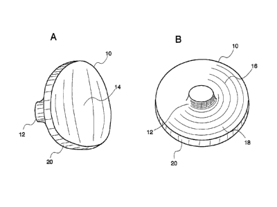
Referring now to FIGS. 1A, 1B, and 1C, there is provided glenoid implant
(10), which is intended to be implanted in the glenoid as part of a TSR
arthroplasty.
Glenoid implant (10) replaces the natural glenoid cavity (see G of FIG. 15)
and
provides a bearing surface against which the head of a humerus or humeral
component may articulate. Glenoid implant (10) includes concave articulating
surface (14) and convex or flat backside surface (16), which can, optionally,
include
roughened or textured surface (18). Glenoid implant (10) can be provided as a
circular design (FIG. 1A and 1C) or as an oblong, oval design (FIG. 1B).
Referring now to FIGs. 2A and 2B, glenoid implant (10) can include short,
backside peg (12) on the medial, convex or flat backside surface (16) of
glenoid
implant (10). Short, backside peg (12) is situated centrally on the medial
(back) side
14
CA 02598659 2007-08-22
WO 2006/093763
PCT/US2006/006330
of glenoid implant (10) and is preferably a cylindrical peg shape that extends
outwardly from glenoid implant (10) away from the back of the implant (16).
Glenoid implant (10), including or excluding short, backside peg (12), is
adapted to be implanted in a prepared cavity of the glenoid (see, e.g., FIG.
12), such
that it is partially or fully inset to the cortical bone of the glenoid, and
is retained with
bone cement or using press-fit techniques. Glenoid implant (10) can be further
secured to the glenoid using one or more screws.
Glenoid component (10) of the present invention includes concave lateral
articulating surface (14) against which the head of a humerus or humeral
component
moves. Glenoid implant (10) is manufactured using a suitable material, for
example,
polyethylene, metal, ceramic, or combinations thereof, with lateral
articulating surface
(14) being smoothly contoured. The radius of curvature of the articulating
glenoid
surface can match the humeral head surface or it can be slightly larger than
the radius
of curvature of the humeral head implant.
In preferred embodiments, glenoid implant (10) has a lateral articulating
surface (14) having a concave circular or oval surface encircled by circular
edge (20).
Circular edge (20) has a thickness in the range of about 3-6 mm, preferably
about 3
mm.
The medial, back side of glenoid implant (10) is preferably roughened or
textured. For example, glenoid implant (10) can include a series of elongated
groves
(18) in multiple locations for receiving bone cement to assist in the cement
augmentation and retention of glenoid implant (10).
In preparing the glenoid to receive glenoid implant (10), the glenoid (G; see,
e.g., FIG. 12) is reamed to receive all or a portion of glenoid implant (10)
so that
CA 02598659 2013-02-08
CA2598659
glenoid implant (10) is circumferentially surrounded by cortical bone of the
glenoid (G),
which aids in the stabilization and security of glenoid implant (10).
Glenoid Drill and Reamer
Referring now to FIGs. 13-16, there will be described a method for preparing a
cavity
in the glenoid for receiving a glenoid implant of the present invention and
apparatus to be
used therewith.
In preparing the cavity in the glenoid (G) to receive glenoid implant (10),
the surgeon
will initially determine the position of the drill site using a guide known in
the art (see, e.g.,
U.S. Patent Nos. 6,712,823; 6,364,910; 5,030,219; and 5,489,310).
A reamer of appropriate size is then chosen based on the size of the sizer
guide
previously chosen. The reamer has a symmetrical head with a plurality of
cutting blades and
a peripheral stop surface. The previously drilled hole is used as a center
guide for the reamer.
The reamer is used to create a cavity in the glenoid surface of the scapula in
which the
prosthetic glenoid component will be installed. After the cavity has been
created, the circular
or oval glenoid component is installed in the cavity, with or without the use
of bone cement.
A method for implanting glenoid implant (10) will now be described with
reference to
FIGS. 13-16. Initially, if a total shoulder arthroplasty is performed, a
humeral implant having
a head portion, discussed below, and a glenoid implant are implanted. Prior to
implantation
of the humeral component into the humerus, glenoid preparation begins. With
the glenoid
cavity (G) of the scapula (S) exposed, an alignment or pilot hole is first
drilled substantially in
the center of the glenoid cavity (G) using, e.g., the drill shown in FIGS. 14,
15, and 26. Once
the pilot hole is drilled,
16
CA 02598659 2007-08-22
WO 2006/093763
PCT/US2006/006330
the glenoid cavity (G) is reamed using a glenoid surface rasp (see bit
attached to the
drill depicted in FIG. 16) attached to a 900 reamer shaft with driver (see
FIG. 26).
The glenoid surface rasp may include a guide pin and a roughened cutting
surface to
create a trough for the glenoid component. The 90 angle of the shaft of the
driver
permits drilling in tight glenoid cavities. Thus, the procedure can be
perfoimed in a
minimally invasive manner because it does not require full circumferential
exposure
of the glenoid, nor does it require a complete capsular release. The 90 shaft
of the
drill includes a quick-connect attachment which receives the quick-connect
drill bit.
The reamer is rotated by suitable power means or by hand to ream the glenoid
cavity.
Following such reaming, the reamer and the guide wire/drill are removed
leaving a
cavity which is wholly contained within the glenoid cavity (G).
Once the holes have been drilled and the glenoid reamed, a provisional
glenoid implant may be used prior to cementing the final glenoid implant to
verify
hole placement, range of motion, and appropriate glenoid size, and to verify
that the
glenoid implant is sufficiently inset. After the proper sized glenoid implant
has been
selected, suitable bone cement, such as polymethylmethacrylate (PMMA) or a
compatible fixation material, is placed in the reamed cavity of the glenoid
vault and in
the roughened outer portions and applied to the medial (back) surface of
glenoid
implant (10), if cement is to be used. Glenoid implant (10) can then be
positioned in
the prepared cavity. Glenoid implant (10) is then held in place until the
cement cures
to assure strong fixation of glenoid implant (10) in the scapula. The head
portion of
the humerus or humeral component may then engage the concave articulating
surface
of the glenoid implant (14).
As can be appreciated, the reaming is contained wholly within the boundary of
the glenoid cavity (G) and therefore does not destroy the peripheral margin of
the
17
CA 02598659 2007-08-22
WO 2006/093763 PCT/US2006/006330
glenoid surface. Additionally, as can be seen in FIG. 7, there is preferably a
slight
overhang of glenoid implant (10) beyond the margin of the natural glenoid
cavity.
This method can be performed using a deltoperctoral or anterolateral surgical
approach. For most cases, a limited deltopectoral incision will be adequate to
allow
exposure to all involved structures. Use of glenoid implant (10) in the
shoulder
arthroplasty procedure allows the surgeon to use a "mini-incision technique,"
similar
to techniques utilized for total knee surgery and total hip surgery.
The glenoid implant of the invention has already been implanted in several
patients according to the patient matched implant (PMI) rules and regulations.
The
implants were designed specifically for patients with inadequate glenoid bone
stock
which could not support a typical keel or peg design.
Humeral Head Cutting Jig
Referring now to FIGS 17-19, humeral head cutting jig (26) according to the
present invention is a simple, low profile humeral cutting jig that can be a
full circle
or part thereof. Cutting jig (26) can be secured to the humeral head using K-
wires,
pins, or screws (27) and is removed after completion of humeral head
resection.
Cutting jig (26) includes handle portion (28).
The cutting jig should be placed along the anatomic neck of the humeral head.
Osteophytes which obscure the junction of the humeral head and humeral shaft
should
be removed in order to accurately mark the level of the anatomic neck
circumferentially from anterior to inferior to posterior. The cutting jig can
be fixed to
the humerus using wires, pins, or screws at the appropriate angle and version
as
determined by the surgeon. The rotator cuff should be carefully protected with
18
CA 02598659 2013-02-08
CA2598659
retractors, and then the humeral cut is performed using an oscillating saw or
osteotome along
the surface of the cutting jig.
Tlw, cutting jig can be manufactured using metal.
Humeral Implant
Referring now to FIGS. 20A-D, humeral implant prosthesis (38) according to the
present invention includes stem (40) having elongated portion (42) optionally
including collar
(44), which prevents humeral implant prosthesis (38) from embedding too deeply
in the
humerus. Humeral implant (38) also includes flange (fin) (46), which aids in
the fixation of
the stem in the humerus and prevents rotation of humeral implant in the
humerus. There may
be just one lateral flange (fin), or there may be two or three flanges (fins),
e.g., with one
lateral, one anterior, and one posterior. The stem length is preferably less
than about 70 mm,
and the stem width is preferably less than about 40 mm (preferably about 30
mm).
At the distal end of the stem, there is rounded portion (48) and at the
proximal end of
the stem is a support surface extending radially from the stem. The support
surface has an
upper planar surface (50) that includes bore (hole with morse taper) (52)
extending inwardly
from the top plane thereof, and which is adapted to be engaged by a humeral
head implant
with a morse taper extension. Modular humeral head implants (both concentric
and eccentric)
are known in the art (see, e.g., U.S. Patent Nos. 4,865,605; 5,314,479;
5,462,563, and
5,489,309, and U.S. Patent Application Nos. 2004/0167629, 2004/0064187). The
plane of
upper planar surface (50) is preferably between about 45 degrees and about 60
degrees to the
axis of the stem.
19
CA 02598659 2007-08-22
WO 2006/093763
PCT/US2006/006330
The entire stem portion, or a portion thereof, is preferably coated with a
porous
material for aiding in the fixation of the humeral implant in the humerus for
a press fit
stem. The implants made for cement fixation can have a smooth surface or a
roughened, textured surface.
Humeral implant (38) can be rectangular or rounded edges, but is significantly
thinner anterior to posterior than medial to lateral. It will have a morse
taper for
securing a standard humeral head implant.
An advantage of the humeral implant of the present invention over current
humeral implant stems is that the humeral implant of the invention is
significantly
shorter than most current stems, which are about 70-115 mm in length. Because
the
humeral implant is shorter, it saves bone because of the narrow metaphyseal
area
required for implantation. The present humeral implant is less than 70 mm in
length,
preferably about 60 mm in length, and less than 40 mm anterior-posterior width
(preferably about 30 mm). Fixation of the present humeral implant depends upon
good interference fixation in the medial-lateral plane when press fit (similar
to some
current total hips). The humeral implant can be fixed using a bone cement,
such as
polymethylmethacrylate (PMMA) or a compatible fixation material, or it can be
press-fit.
The invention will now be described by the following examples. The
following examples are meant to illustrate the invention. They are not meant
to limit
the invention in any way.
CA 02598659 2007-08-22
WO 2006/093763 PCT/US2006/006330
EXAMPLES
Example 1
A 62 year old woman presented with progressive, debilitating shoulder pain
from osteoarthritis, which she had experienced for approximately 15 years. She
had
constant pain (rated 9/10) and difficulty washing her hair, fastening her bra,
lifting a
cup of coffee, and performing other daily activities. The preoperative
radiographs and
CT scan showed severe shoulder arthritis and glenoid bone loss that would
preclude
the use of a keeled or pegged glenoid implant. There was concern that a
hemiarthroplasty procedure (replacement of the humeral ball, which would leave
the
arthritic glenoid socket bare) would not relieve the patient's pain.
A total shoulder replacement using an inset glenoid implant of the invention
and a standard humeral implant was performed. The smaller size and
circumferential
fixation of the inset glenoid implant allowed safe placement of the prosthesis
within
the confines of the patient's deficient glenoid cavity.
The deficient glenoid vault was not fractured and the fixation was very
stable.
The patient had 100% relief of pain only 1 week after surgery. Her own
assessment
of shoulder function 4 weeks after surgery was 56% of.normal (American
Shoulder
and Elbow Society validated outcome score [ASES score]) was 56 compared to 16%
of normal before the surgery (ASES score 16).
This surgery was performed through the "mini-incision total shoulder
technique" described above. Figure 25 shows the surgical incision 4 weeks post-
operatively. Figure 24, which shows a more typical total shoulder incision,
clearly
demonstrates the improved cosmetic appearance and reduced incision size
achieved
using the "mini-incision total shoulder technique" described above. Figures 21-
23 are
intraoperative pictures of the implanted inset glenoid prosthesis in this
patient.
21
CA 02598659 2013-02-08
CA2598659
Example 2
An 81 year old woman presented with severe shoulder pain and stiffness. She
had
severe shoulder arthritis with medial wear causing glenoid bone loss. Her own
assessment of
shoulder function was 25% of normal (American Shoulder and Elbow Society
validated
outcome score EASES score] was 25).
A total shoulder replacement using an inset glenoid implant prosthesis was
performed.
Two months after her surgery, the patient had no pain and exhibited improved
function. Her
own assessment of shoulder function was 70% of normal (American Shoulder and
Elbow
Society validated outcome score [ASES score] was 70).
While the invention has been described in connection with specific embodiments
thereof, it will be understood that it is capable of further modifications and
this application is
intended to cover any variations, uses, or adaptations of the invention
following, in general,
the principles of the invention and including such departures from the present
disclosure that
come within known or customary practice within the art to which the invention
pertains and
may be applied to the essential features hereinbefore set forth.
22